ÉCOLE DE TECHNOLOGIE SUPÉRIEURE UNIVERSITÉ DU QUÉBEC
THESIS PRESENTED TO
ÉCOLE DE TECHNOLOGIE SUPÉRIEURE
IN PARTIAL FULFILLMENT OF THE REQUIREMENTS FOR THE DEGREE OF DOCTOR OF PHILOSOPHY
Ph.D.
BY
Miloud REZKALLAH
DESIGN AND CONTROL OF STANDALONE AND HYBRID STANDALONE POWER GENERATION SYSTEMS
MONTREAL, 25 APRIL 2016
This Creative Commons licence allows readers to download this work and share it with others as long as the author is credited. The content of this work may not be modified in any way or used commercially.
THIS THESIS HAS BEEN EVALUATED
BY THE FOLLOWING BOARD OF EXAMINERS
Mr. Ambrish Chandra, Thesis Supervisor
Department of Electrical Engineering, École de Technologie Supérieure
M. Pierre Bourque , Chair, Board of Examiners
Department of Software and IT Engineering, École de Technologie Supérieure
M. Kamal Al Haddad, Member of the jury
Department of Electrical Engineering, École de Technologie Supérieure
M. Sheldon S. Williamson, External Evaluator
Department of Electrical, Computer and Software Engineering, University of Ontario Institute of Technology
M. Mohammed El Kahel, External Evaluator GE Renewable Energy, Hydro North America
THIS THESIS WAS PRENSENTED AND DEFENDED
IN THE PRESENCE OF A BOARD OF EXAMINERS AND THE PUBLIC APRIL 8, 2016
ACKNOWLEDGMENTS
I would like to express my deep and sincere gratitude to my research director Prof. Ambrish Chandra for given me opportunity to go through the PhD program. I have been immensely benefitted from his technical expertise and experience in developing my research skill. It has been an honor for me to be his PhD student.
I am deeply grateful to Prof. Bhim singh for his detailed guidance and constructive advices. From which I have learned and developed important technical skills to become better researcher.
My sincere gratitude goes to Dr Abdelhamid Hamadi and Dr Shailendra Sharma for their guidance, support and continuous encouragement.
Special thanks to Prof. Kamal Al-Haddad as director of GRÉPCI for giving me access to GRÉPCI Lab.
I would like to show my gratitude to Mr. Yves Robitaille and Mr. George, the technical support staff at the electrical engineering department at ÉTS for their help. I would also like to thank my colleagues at Indian Institute of Technology (IIT) Delhi and at GREPCI for their wonderful company and support.
CONCEPTION ET CONTROLE DES SYSTEMES AUTONOMES ET DES SYSTEMES HYBRIDES AUTONEMES DE GEGERATION DE PUISSANCE
Miloud REZKALLAH
RÉSUMÉ
Plusieurs régions éloignées, des infrastructures des télécommunications, les installations d'extraction et les zones résidentielles isolées utilisent actuellement des générateurs diesel pour répondre à leur besoin en électricité. Cependant, cette source d'énergie est basée sur le carburant diesel qui est coûteux et polluant. Considérant le coût, la disponibilité et la fiabilité de l'électricité fournie par cette source d'énergie polluante, il est préférable d’opter pour une nouvelle solution basée sur des sources d’énergies renouvelables disponibles localement, moins dispendieux et compatibles avec l'environnement, tels que, l’éolien, le solaire, la biomasse ou l'hydroélectricité. Pour assurer une alimentation stable et continue, le système de production d'énergie autonome hybride basé sur de nombreuses sources d'énergie renouvelables est proposé dans cette étude comme une solution efficace et rentable. Par contre, cette option nécessite une conception, et un développement d'algorithmes robustes pour une gestion sécuritaire et efficace. Étant donné que la plupart de sources d'énergie renouvelables sont intermittentes, les convertisseurs de puissance sont alors nécessaires pour l’extraction de la puissance maximale, pour assurer la conversion d'énergie, et veiller à la régulation de la tension et de la fréquence du système au point de raccordement au réseau (PCC). Malheureusement, l'utilisation de plusieurs convertisseurs de puissance cause des problèmes de coût et de fiabilité. En outre, les batteries et la charge secondaire sont des éléments clés dans ces types d'installation. Les batteries assurent une alimentation électrique continue, maintient la tension et la fréquence constantes au PCC et permet une gestion efficace de l'énergie à long terme du système. La charge secondaire est utilisée pour dissiper l’excès de la puissance produite afin de maintenir l'équilibre de puissance entre les charges et les sources d'énergie en cas où les batteries sont complètement chargées. Par contre, la tension et la fréquence ne peuvent être maintenues constantes si les charges secondaires ne sont pas purement résistives et par conséquent, leur contrôle affecte la qualité de l’énergie par la génération des harmoniques dans le système surtout si elles sont connecté au PCC. Afin d'obtenir un rendement élevé avec un coût réduit à partir des différentes sources d'énergie, minimiser l'utilisation du combustible diesel, et assurer une alimentation continue, propre et stable, plusieurs topologies basées sur la combinaison de deux sources d’énergies entrainées par différents générateurs électriques sont proposées dans ce travail de recherche. Plusieurs approches de contrôle sont conçues pour atteindre ces objectifs. Pour protéger les batteries contre la surcharge de tension et minimiser le risque de la détérioration de la qualité d'énergie, la charge secondaire utilisée dans les nouvelles topologies sont connectées au bus à courant continu au lieu de celui côté alternatif. Des modélisations et des analyses de stabilité sont effectuées. La performance des systèmes hybrides autonomes proposés ont été validés théoriquement par simulation en utilisant MATLAB / Simulink. Des validations
expérimentales de deux topologies proposées ont été effectuées sur un prototype mis au point dans le laboratoire.
Mots-clés: Système Hybride Autonome, panneaux solaire, éolienne, microcentrale hydroélectrique, générateur diesel, machines électriques, générateur à vitesse fixe et à vitesse variable, stockage d’énergie, contrôle de la tension et de la fréquence, amélioration de qualité d’énergie et protection des batteries contre le surcharge de tension.
CONTROL AND DESIGN OF STANDALONE AND HYBRID STANDALONE POWER GENERATION SYSTEMS
Miloud REZKALLAH
ABSTRACT
Many remote areas, such as telecommunications infrastructures, mining facilities and isolated residential areas depend only on diesel generators (DGs) to support their electricity requirements. However, this energy source is based on diesel fuel, which is costly and pollutant. Considering the cost, availability and reliability of the electricity provided by DGs, it is very important to find a new solution based on clean energy sources available locally, which are inexpensive and environmentally friendly, such as, wind, solar, biomass or hydro. Nevertheless, to ensure a stable and uninterruptible power supply in these remote areas, hybrid standalone power generation system based on various renewable energy sources is advised. This solution is effective and cost-efficient, however, it requires a complex design, planning, and control optimization methods. Beside, most of those renewable energy sources are intermittent and either alternative or continue by nature. Therefore, power converters are required to ensure power conversion, to get the maximum power point tracking, as well as to regulate the voltage and the system frequency at the Point of Common Coupling (PCC). Unfortunately, using several power converters introduces cost and reliability concerns. Battery energy storage system (BESS) and dump loads are key-elements in those types of installations. They ensure uninterruptible power supply to the connected load during transition and maintain the voltage and frequency constant at the PCC by dissipate the extra produced power in the system. Unfortunately, dump loads is not able to maintain the voltage and frequency constant if is not purely resistive. Its control affects the power quality by injecting harmonics in the system. To get high efficiency with reduced cost from different energy sources, to minimize the use of the diesel generator, and to ensure clean, stable and uninterruptable power supply to the local loads, many topologies employing different electrical generators are proposed in this research work. For optimal and safe operation of standalone and hybrid standalone power generations systems, many control approaches are developed. Furthermore, for all topologies, dump load is placed at the DC side instead of AC side in order to protect the BESS from the overcharging and to minimize the risk of the deterioration of the power quality. Modeling and stability analysis are investigated. The suitability of proposed SPGSs and HSPGSs at practical operating conditions is demonstrated through simulation results using MATLAB/ Simulink. Experimental validations of two proposed topologies have been performed on a prototype developed in the laboratory.
Keywords: Standalone power generation system, solar PV array, wind turbine, micro-hydro power, diesel generator, electrical machines, variable and fixed speed generator, storage energy, voltage and frequency control, power quality improvement and protection of BESS from overcharging.
TABLE OF CONTENTS
Page
INTRODUCTION ...27
CHAPITRE 1 LITERATURE REVIEW ...36
1.1 Introduction ...36
1.2 Definition and Role of Standalone and Hybrid Standalone Power Generation Systems ...36
1.3 Principal Elements of Hybrid Standalone Power Generation Systems ...37
1.3.1 Renewable Energy Sources ... 37
1.3.1.1 Wind Turbine Conversion System ... 38
1.3.1.2 Hydro Power System ... 41
1.3.1.3 Solar Photovoltaic (PV) System ... 42
1.3.1.4 Diesel Generator ... 43
1.3.2 Dump loads ... 46
1.3.3 Battery Energy Storage System ... 47
1.3.4 Power Electronics Device ... 48
1.4 Integrated Configurations for Hybrid Standalone Power Generation System ...48
1.4.1 DC microgrid Configuration for Hybrid Standalone Power Generation Systems ... 49
1.4.2 AC Microgrid Configuration for Hybrid Standalone Power Generation Systems ... 50
1.4.3 Hybrid AC/DC Microgrid Configuration for Hybrid Standalone Power Generation Systems ... 51
1.5 System Control for Energy Flow Management in Hybrid Standalone Power Generation Systems ...52
1.5.1 Centralized Control Scheme for Hybrid Standalone Power Generation Systems ... 52
1.5.2 Distributed Control Scheme for Hybrid Standalone Power Generation Systems ... 53
1.5.3 Hybrid centralized and distributed control scheme for HSPGS ... 54
1.6 Problematic ...54
1.6.1 Problems Related to the Intermittence of the Renewable Energy Sources ... 55
1.6.2 Maximization of the Generated Power from Renewable energy sources... 55
1.6.3 Fuel Consumption Minimisation for DG ... 57
1.6.4 Underutilization of Power Electronics Devices Rating ... 57
1.6.5 Synchronization issues between ESs and PCC ... 57
1.6.5.1 AC Voltage Regulation ... 58
1.6.5.2 System Frequency Regulation ... 58
1.6.5.3 Power Quality Requirement ... 58
1.8 Methodology ...59
CHAPITRE 2 MODELING OF THE ELEMENTS OF STANDALONE POWER GENERATION SYSTEMS ...65
2.1 Introduction ...65
2.2 Modeling of the Wind Turbine ...65
2.2.1 Aerodynamic conversion ... 65
2.2.2 Rotor Optimal Tip Speed Ratio ... 68
2.2.3 Transmission ... 69
2.3 Modeling of the solar PV array ...70
2.3.1 Mathematical model of PV cell ... 71
2.4 Micro-Hydro power ...72
2.4.1 Micro-Hydro power and governor model ... 72
2.5 Diesel Generator ...78
2.5.1 Diesel Prime Mover and Governor ... 78
2.6 Classification and modeling of the electrical machines ...80
2.6.1 Mathematic model of the induction machines ... 81
2.6.1.1 Mathematical model of the Doubly-Fed induction generator .... 81
2.6.1.2 Mathematical model of the squirrel cage induction generator ... 87
2.6.2 Mathematic model of synchronous machine ... 88
2.6.3 Mathematical model of permanent magnetic synchronous generator ... 96
2.6.4 Mathematical model of Permanent Magnetic Brushless Direct Current Generator ... 100
2.6.5 Mathematical model of Synchronous Reluctance Generator ... 103
2.7 Power Electronics Interface ...105
2.7.1 Modeling of the DC/AC inverter ... 106
2.7.2 Modeling of the DC/DC boost converter ... 109
2.7.3 Modeling of the DC/DC buck boost converter ... 109
2.8 Conclusion ...110
CHAPITRE 3 STANDALONE POWER GENERATING SYSTEM EMPLOYING SOLAR-PHOTOVOLTAIC POWER ...111
3.1 Introduction ...111
3.2 System Description ...111
3.3 Modeling and Control Strategy ...112
3.3.1 Modeling of Solar PV Array ... 112
3.3.2 Mathematical Model of the DC/DC Boost Converter ... 113
3.3.3 Maximum Power Tracking Based on Sliding Mode Approach ... 114
3.3.3.1 Choice of Sliding Surface ... 114
3.3.3.2 Determination of the Equivalent Control ... 115
3.3.3.3 System Stability Analysis ... 116
3.3.4 Overvoltage Protection of the BESS ... 118
3.3.5 Mathematical Model of the CC-VSC ... 120
3.3.6 AC Voltage Regulation Based on Sliding Mode Approach ... 121
3.3.6.2 Determination of the Equivalent Control ... 122
3.3.6.3 Stability Analysis ... 124
3.3.7 Selecting the rating of BESS... 127
3.4 Simulation Results and Discussion ...128
3.5 Experimental Results and Discussion ...132
3.6 Conclusion ...136
CHAPITRE 4 HYBRID STANDALONE POWER GENERATION SYSTEMS EMPLOYING SOLAR PV ARRAY AND DIESEL GENERATOR ...137
4.1 Introduction ...137
4.2 Topology Designs for HSPGS based on Solar PV Array and DE Driven Fixed Speed Generators ...138
4.2.1.1 System Description and Control ... 139
4.3 Topology Designs of Hybrid Standalone Power Generation System based on PV Array and DE Driven Variable Speed Generators ...153
4.3.1 System Description and Control ... 155
4.3.1.1 Model of the variable speed DG ... 157
4.3.1.2 Control of the Rotor Side Converter ... 158
4.3.1.3 Control of the interfacing DC/AC inverter ... 162
4.4 Simulation Results and Discussion ...164
4.4.1 Performance of the HSPGS power generation using PV and DG driven fixed speed SG ... 164
4.4.2 Performance of the HSPGS power generation using PV and DG driven variable speed DFIG ... 171
4.5 Conclusion ...178
CHAPITRE 5 HYBRID STANDALONE POWER GENERATION SYSTEM EMPLOYING SOLAR PV ARRAY AND MHP ...179
5.1 Introduction ...179
5.2 Topology designs of hybrid standalone power generation system based on PV array and MHP driven fixed speed generators ...180
5.2.1.1 Description and control of hybrid standalone power generation system based on PV and MHP driven fixed speed SyRG ... 181
5.2.1.2 Description and control of hybrid standalone power generation system based on PV and MHP driven fixed speed SCIG ... 184
5.3 Simulation results and discussion ...193
5.3.1 Performance of the hybrid standalone power generation system based on solar PV and MHP driven fixed speed SyRG ... 193
5.3.1.1 Performance analysis under load and solar irradiation change ... 193
5.3.1.2 Performance analysis under balanced and unbalanced nonlinear loads ... 195
5.3.1.3 Performance analysis when the BESS becomes fully
charged (SOC%=100%) ... 198
5.3.2 Performance of the hybrid standalone power generation system based on solar PV and MHP driven fixed speed SCIG ... 199
5.3.2.1 Performance analysis under load and solar irradiation change ... 199
5.3.2.2 Performance analysis under unbalanced linear load ... 201
5.3.2.3 Performance analysis under unbalanced nonlinear load ... 202
5.3.2.4 Performance analysis under completely removed load ... 203
5.4 Conclusion ...204
CHAPITRE 6 HYBRID STANDALONE POWER GENERATION SYSTEM EMPLOYING SOLAR PV ARRAY AND WT ...205
6.1 Introduction ...205
6.2 Topology designs of hybrid standalone power generation system based on PV array and WT driven fixed speed generators ...206
6.2.1.1 Description and control of hybrid standalone power generation system based on solar PV array and WT driven fixed speed SCIG ... 207
6.2.1.2 Control algorithms for solar PV array and WT driven fixed speed SCIG ... 209
6.3 Topology designs of hybrid standalone power generation system based on solar PV array and WT driven variable speed generators ...211
6.3.1.1 Control algorithms for solar PV array and WT driven variable speed SyRG ... 212
6.3.1.2 Description and control of hybrid standalone power generation system based on solar PV array and WT driven variable speed PMBLDCG ... 219
6.3.2 Control design of the DC/DC Boost Converter for PV side ... 220
6.3.2.1 MPPT Algorithm Based on Sliding Mode Approach for solar PV array ... 221
Controller gain design ... 226
6.3.3 Control Design for DC-DC Boost Converter for WT side ... 228
6.3.3.1 Maximum Power Tracking Based on Sliding Mode Approach for WT ... 229
6.3.4 Control of CC-VSC... 235
6.4 Simulation results and discussion ...239
6.4.1 Performance of HSPGS based on solar PV array and WT driven fixed speed SCIG ... 239
6.4.2 Performance of HSPGS system based on solar PV array and WT driven variable speed SyRG... 245
6.4.3 Performance of HSPGS based on solar PV array and WT driven variable speed PMBLDCG ... 251
6.4.3.1 Simulation results... 251
6.5 Conclusion ...259
CHAPITRE 7 HYBRID STANDALONE POWER GENERATION SYSTEM EMPLOYING WT AND DG ...261
7.1 Introduction ...261
7.2 Topology designs of HSPGS based on DG and WT driven fixed speed generators ...262
7.2.1.1 Description and control of hybrid standalone power generation system based on WT and DG driven fixed speed SG and PMSG ... 263
7.3 Topology designs of hybrid standalone power generation system employing DG and WT driven variable speed generators ...269
7.3.1 Description and control of HSPGS employing WT and DG driven variable speed PMBLDCG and PMSG ... 271
7.4 Simulation results and discussion ...279
7.4.1 Performance of the HSPGS based on DG and WT driven fixed speed SG and PMSG ... 279
7.4.2 Performance of the hybrid standalone power generation system based on DG and WT driven variable speed PMSG and PMBLDCG ... 290
7.5 Conclusion ...296
CONCLUSION ...297
RECOMMENDATIONS ...301
APPENDIX I SYSTEMS PARAMETERS ...303
APPENDIX II LABORATORY SETUP DETAILS ...308
LIST OF TABLES
Page
Table 1.1 Classification of ESS based on time frame ...47
Table 1.2 Classification of ESS based on the form of energy storage ...48
Table 2.1 Classification of PMSG and BLDCG ...100
Table 3.1 Signs of the first and the second terms of (3.22) ...117
Table 3.2 Signs of the Terms Given in (3.35) ...126
Table 3.3 Signs of the Terms 1,2,3 and 4 of (3.47) ...126
LIST OF FIGURES
Page
Figure 0.1 Mean wind speed in Quebec ...29
Figure 0.2 Photovoltaic potential in Canada ...30
Figure 1.1 WT based on fixed speed generators: a) SCIG and b) SG ...38
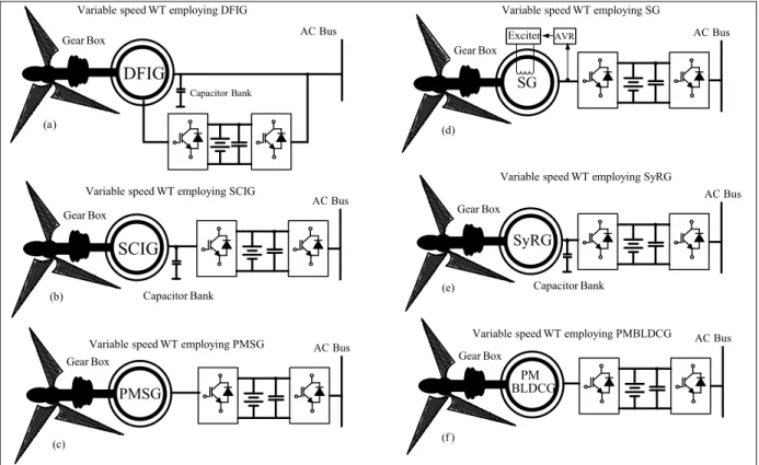
Figure 1.2 SPGS based on WT driven variable speed generators ...40
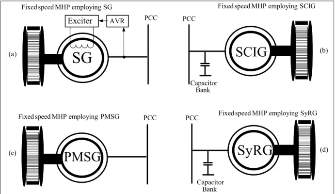
Figure 1.3 Fixed speed MHP employing: a) SG, b) SCIG, c) PMSG and d) SyRG ...42
Figure 1.4 SPGS based on solar PV array ...43
Figure 1.5 DE driven fixed speed SG ...44
Figure 1.6 DE driven variable speed generators ...45
Figure 1.7 Model of the ELC Taken from Singh and Murthy (2006) ...46
Figure 1.8 DC microgrid configuration for HSPGS...49
Figure 1.9 AC microgrid configuration for HSPGS...50
Figure 1.10 Hybrid AC/DC microgrid configuration HSPGS ...51
Figure 1.11 Centralized control scheme for HSPGS ...53
Figure 1.12 Distributed control scheme for HSPGS ...53
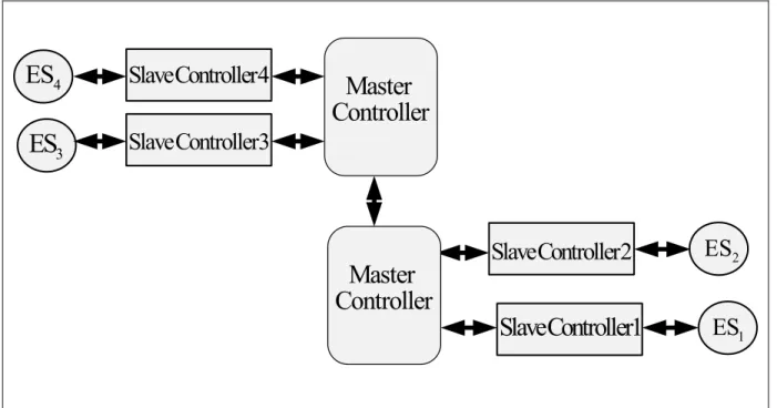
Figure 1.13 Hybrid centralized and distributed control scheme for HSPGS ...54
Figure 1.14 MPPT control methods for WT ...56
Figure 2.1 Wind speed variation in ideal model of a WT ...66
Figure 2.2 Power coefficient Cp and the interference parameters b ...67
Figure 2.3 Power coefficient- Tip speed ratio Characteristic ...68
Figure 2.4 Transmission for WT ...69
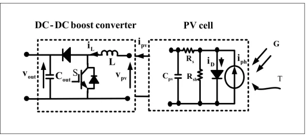
Figure 2.6 Equivalent electrical circuit of the PV cell and the DC-DC boost converter ...70
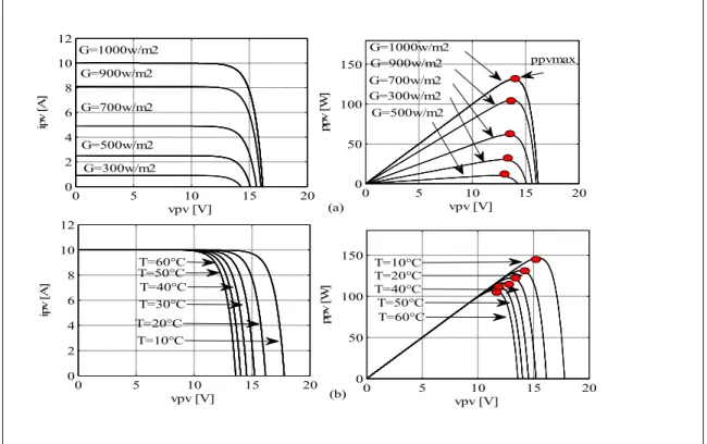
Figure 2.7 Characteristics I-V and V-P of PV for: a) fixed T and varying G b) fixed G and varying T ...72
Figure 2.8 Simplified schematic of micro hydro power plant ...73
Figure 2.9 Simplified functional block diagram of MHP power plants ...78
Figure 2.10 Simplified block diagram of the DE and its governor ...80
Figure 2.11 Classification of electrical machines ...80
Figure 2.12 Equivalent circuit of DFIG in d-q axis reference frame ...86
Figure 2.13 Equivalent circuit of SCIG in d-q - axis reference frame ...88
Figure 2.14 (a) schematic diagram of SG, (b)circuit of rotor and (c) circuit of stator ...89
Figure 2.15 Representation of : a) SG windings, b) and c) completed d-q axis windings ...95
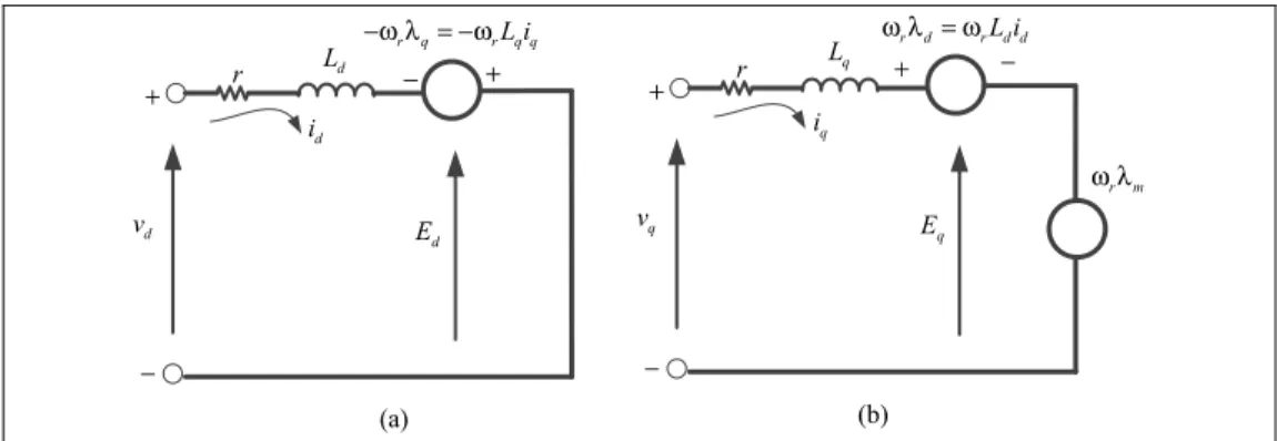
Figure 2.16 Equivalent circuit of the PMSG: a) d-axis and b) q-axis ...99
Figure 2.17 Phase back EMF waveforms of PMBLDCG and PMSG ...101
Figure 2.18 Equivalent circuit of SyRM : a) d-axis and b) q-axis ...103
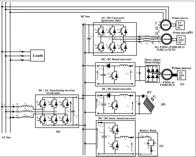
Figure 2.19 Power converters for SPGS and HSPGS ...106
Figure 3.1 SPGS based on solar PV array ...112
Figure 3.2 Control of the DC/DC Boost converter ...118
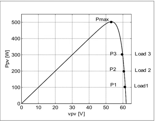
Figure 3.3 P-V characteristic of the solar PV array ...120
Figure 3.4 Control of CC-VSC...124
Figure 3.5 Simulation results of capacitor currents and load voltage in d-q axis ...127
Figure 3.6 Dynamic performance of the SPGS based on solar PV array under solar insolation and load change ...129
Figure 3.7 I-V Characteristic curve of PV array at T=20°C and G=1000w/m2 ...130
Figure 3.8 Dynamic performance of SPGS based on solar PV when SOC% of BESS is equal to 100% ...131
Figure 3.10 Dynamic performance of SPGS based on solar PV array under load
variation ...134
Figure 3.11 Dynamic performance of SPGS based on solar PV array under solar irradiation change...135
Figure 4.1 Classification of HSPGS based on PV array and DG driven fixed and variable speed generators ...137
Figure 4.2 PV-DG HSPGS employing fixed speed generators ...139
Figure 4.3 HSPGS based on solar PV array and DE driven fixed speed SG ...140
Figure 4.4 Flowchart of Perturbation and observation MPPT algorithm ...141
Figure 4.5 Block diagram for DG ...142
Figure 4.6 Model of the analogue AVR ...143
Figure 4.7 Fuel consumption for variable and fixed speed operation of DG ...144
Figure 4.8 Proposed control algorithm for controlled switch ...146
Figure 4.9 Dump load control algorithm ...147
Figure 4.10 Modified instantaneous power theory control algorithm ...149
Figure 4.11 HSPGS based on solar PV array and DE driven variable speed generators ...154
Figure 4.12 HSPGS based on solar PV array and DE driven variable speed DFIG ...155
Figure 4.13 DFIG operation modes; a) super-synchronous mode and ...156
Figure 4.14 Model of the variable speed DE ...157
Figure 4.15 Control algorithm for rotor side converter ...162
Figure 4.16 Control algorithm for the interfacing DC/AC inverter ...164
Figure 4.17 Dynamic response of PV-DG HSPGS based on fixed speed SG when the SOC% of BESS is greater to 50% ...165
Figure 4.18 Zoom 1 of the results shown in Fig 4.17 ...166
Figure 4.19 Zoom 2 of the results shown in Fig 4.17 ...167
Figure 4.21 Dynamic response of PV-DG HSPGS based on fixed speed SG when
the SOC% of BESS is less than 50% ...169
Figure 4.22 Zoom the results shown in Fig 4.21 between t=0.7 s to t= 0.9 s. ...170
Figure 4.23 Dynamic response of the PV-DG HSPGS based on variable speed DFIG when the SOC% of BESS is less than 100% and greater than 50% ...172
Figure 4.24 Dynamic performance of PV-DG HSPG based on variable speed DFIG under linear load change and fixed solar irradiation and when the state charge of battery is less than 50% ...173
Figure 4.25 Dynamic performance of PV-DG HSPG under balanced and unbalanced nonlinear load and fixed solar irradiation and when the state charge of battery is less than 50%...175
Figure 4.26 Zoom of the results shown in Fig.4.25 between t= 0.7 s and t= 0.9s ...176
Figure 4.27 Dynamic performance PV-DG HSPGS based on DFIG when SOC % of BESS is equal to 100% ...177
Figure 5.1 Classification of HSPGS power generation based on PV array and MHP driven fixed speed generators ...180
Figure 5.2 HSPGS based on solar PV array and MHP driven fixed speed generators ...181
Figure 5.3 HSPGS based on solar PV array and MHP driven fixed speed SyRG ...182
Figure 5.4 Characteristics torque-speed of MHT ...183
Figure 5.5 Proposed HSPGS based on solar PV array and MHP driven fixed speed SCIG ...184
Figure 5.6 Perturbation and Observation MPPT Method ...185
Figure 5.7 Ppv-Vpv Characteristic of the proposed solar PV array ...186
Figure 5.8 Dump load control algorithm ...187
Figure 5.9 System Frequency Control Algorithm ...189
Figure 5.10 Proposed control algorithm for the DC/AC interfacing inverter ...192
Figure 5.11 Dynamic performance of PV-MHP HSPGS based on fixed speed SyRG during load and solar irradiation change ...194
Figure 5.13 Dynamic performance of PV-MHP HSPGS based on fixed speed SyRG ...196
Figure 5.14 Dynamic performance of PV-MHP HSPGS based on fixed speed SyRG ...197
Figure 5.15 Dynamic performance of the PV-MHP HSPGS based on fixed speed SyRG when the SOC% of BESS is equal to 100% ...198
Figure 5.16 Dynamic performance of PV-MHP SPGS based on fixed speed SCIG under solar and load irradiation change ...200
Figure 5.17 Zoom1 of the results shown in Fig.5.16 between t=0.45s and t= 0.55 s ...201
Figure 5.18 Zoom2 of the results shown in Fig.5.16 between t=1.05 s and t= 1.15 s ...202
Figure 5.19 Zoom3 of the results shown in Fig.5.16 between t=1.35 s and t= 1.45 s ...203
Figure 6.1 Classification of HSPGS based on PV array and WT driven fixed and variable speed generators ...205
Figure 6.2 HSPGS based on solar PV array and WT driven fixed speed generators ...207
Figure 6.3 HSPGS based on PV array and WT driven fixed speed SCIG ...208
Figure 6.4 Turbine power-speed characteristics for β =0° ...208
Figure 6.5 d-q control algorithm for DC/AC inverter ...209
Figure 6.6 HSPGS based on solar PV array and WT driven variable speed generators ....211
Figure 6.7 HSPGS based on solar PV array and WT driven variable speed SyRG ...213
Figure 6.8 Power-speed characteristics ...214
Figure 6.9 Rotor oriented control (ROC) for SyRG ...216
Figure 6.10 Control of the DC/AC interfacing inverter ...218
Figure 6.11 HSPGS based on solar PV array and WT driven variable speed PMBLDCG ...219
Figure 6.12 Proposed SMC based control algorithm for the DC-DC boost converter 1 for solar PV array side ...221
Figure 6.13 Dynamic response of the inductor current for different gain control values ....226
Figure 6.15 Proposed feedback control algorithm for the DC-DC boost converter
WT side ...228 Figure 6.16 Experimental characteristic of ωr=f(iWT) ...232
Figure 6.17 QLC based proposed control algorithm of CC-VSC ...237 Figure 6.18 Dynamic performance of the PV-WT HSPGS based on fixed speed
SCIG under weather conditions change ...240 Figure 6.19 Zoom of the results shown in Fig 6.18 between t=0.75 s and t=0.85s ...241 Figure 6.20 Steady state performance of PV-WT HSPGS employing fixed speed
SCIG under balanced nonlinear load ...242 Figure 6.21 Steady state performance of PV-WT HSPGS employing fixed speed
SCIG under unbalanced nonlinear load ...243 Figure 6.22 Dynamic performance of the PV-WT HSPGS employing fixed speed
SCIG when SOC% is equal to 100% ...244 Figure 6.23 Dynamic performance of PV-WT HSPGS employing variable speed
SyRG under weather conditions change ...246 Figure 6.24 Dynamic performance of PV-WT HSPGS employing variable speed
SyRG under balanced and unbalanced linear load ...248 Figure 6.25 Dynamic performance of PV-WT HSPGS employing variable speed
SyRG under balanced and unbalanced nonlinear load ...249 Figure 6.26 Dynamic performance of PV-WT HSPGS employing variable speed
SyRG when SOC% of BESS becomes equal to 100% ...250 Figure 6.27 Dynamic performance of PV-WT HSPGS under load variation ...251 Figure 6.28 Dynamic performance of: a) PMPBLDCG under wind speed
variation b) solar PV array and solar irradiations change ...252 Figure 6.29 Experimental hardware configuration ...253 Figure 6.30 Dynamic performance of the proposed PV-WT HSPGS employing
variable speed PMBLDCG under load change ...255 Figure 6.31 Dynamic performance of the PMBLDCG under wind speed variation ...256 Figure 6.32 Dynamic performance of PV-WT HSPGS under solar insolation
Figure 7.1 Classification of HSPGS based on PV array and WT driven fixed and
variable speed generators ...261 Figure 7.2 HSPGS based on WT and DG driven fixed speed generators ...263 Figure 7.3 HSPGS based on WT and DG driven fixed speed PMSG and SG ...264 Figure 7.4 Modified SRF control algorithm ...265 Figure 7.5 HSPGS based on WT and DG driven variable speed generators ...270 Figure 7.6 HSPGS based on WT and DG driven variable speed PMBLDCG
and PMSG ...271 Figure 7.7 Control of the DG side DC-DC boost converter ...272 Figure 7.8 Control of the DC-DC WT side boost converter ...274 Figure 7.9 Positive, Negative and Zero sequence components ...275 Figure 7.10 Control of the DC/AC inverter ...278 Figure 7.11 Dynamic performance of WT-DG HSPGS employing fixed speed
generators under wind speed and loads change when the SOC% is greater than 50% ...280 Figure 7.12 Zoom1 of the results shown in Fig.7.11 between t= 1.48s to t= 1.55 s ...281 Figure 7.13 Zoom2 of the results shown in Fig.7.11 between t= 2.48 s and t=2.55 s ...282 Figure 7.14 Dynamic performance of WT-DG HSPGS based on fixed speed
generators when SOC% is less than 50% ...283 Figure 7.15 Zoom1 of the results shown in Fig.7.14 between t=0.98 s and t=1.05 s ...285 Figure 7.16 Zoom2 of simulation results shown in Fig.7.14 between t =1.48 s
and t=1.55s ...286 Figure 7.17 Dynamic performance of interfacing inverter under balanced nonlinear
load ...287 Figure 7.18 Dynamic performance of interfacing inverter under unbalanced nonlinear
load ...288 Figure 7.19 Dynamic performance of WT-DG HSPGS employing fixed speed
Figure 7.20 Dynamic response of WT-DG HSPGS based on variable speed generators when the SOC% of BESS is less than 100% and more
than 50% ...291 Figure 7.21 Dynamic response of WT-DG HSPGS based on variable speed generators
when SOC% of BESS is less than 50% ...292 Figure 7.22 Dynamic performance of the of WT-DG HSPGS based on variable speed
generators under unbalanced linear load ...293 Figure 7.23 Dynamic performance of WT-DG HSPGS based on variable speed
generators under unbalanced nonlinear load ...294 Figure 7.24 Dynamic performance of WT-DG HSPGS based on variable speed
LIST OF ABREVIATIONS
AC Alternative Current
AVR Automatic Voltage Regulation BESS Battery Energy Storage System
CC-VSC Current Control Voltage Source Converter DFIG Doubly Fed Induction Generator
DC Direct Current
DE Diesel Engine
DG Diesel Generator
EFM Energy Flow Management
ES Energy Source
ELC Electronic Load Controller
HP Hydropower
HSPGS Hybrid Standalone Power Generation System HCSC Hill-Climb Search Control
LHP Large Hydropower MHP Medium Hydropower
Mini-HP Mini Hydropower
Micro-HP Micro Hydropower
MW Megawatts
MPPT Maximum Power Point Tracking PCC Point Common Coupling
PSFC Power Signal Feedback Control
PMBLDCG Permanent Magnetic Brushless Direct Current Generator PMSG Permanent Magnetic Synchronous Generator
PV Solar Photovoltaics Panel QLC Quasi-Linear Controller RES Renewable Energy Source RSC Rotor Side converter
SG Synchronous Generator SCIG Squirrel Cage Induction Generator
SyRG Synchronous Reluctance Generator SHP Small Hydropower
SSC Stator Side Converter
SPGS Standalone Power Generation System SMC Sliding Mode Control Approach TSRC Tip Speed Ratio Control
WT Wind Turbine
WESC Wind Energy System Conversion SFR System Frequency Regulation
INTRODUCTION
Canada is among the countries that have shown requirement of electrical power in isolated areas such as telecommunications infrastructure (cellular, microwave, optical ...), mining facilities, routing of oil and gas, as well as, isolated residential areas, which are far and not connected to the main grids. For their electricity requirements, the majority of those areas depend on diesel fuel, which is relatively inefficient, very expensive and responsible for emission of large amounts of greenhouse gases emission (GHG).
During the past several years, the oil prices have achieved historic highs, peaking at 147$/barrel in July, 2008, averaging over 100$/barrel during 2011, averaging over 110$/barrel until October 2014, and then it fell to 80$/barrel. Recently, the oil price is around 30$/barrel. Despite this considerable drop, the diesel fuel prices are losing only a few cents in some provinces in Canada. According to statistic Canada, in St. John's Newfoundland, the diesel fuel lost only 5.7 ¢/L, and in Whitehorse in Yukon is increased by 3.5 ¢/L and in Yellowknife in Northwest Territories is set to rise up to 9.3 ¢/L in October 2014 compared to 2013. According to Statistics Canada (http://www5.statcan.gc.ca), the decline in crude oil prices is not felt at the pump in this region. However, the pump price gasoline only decreased by 11.8C/L from a high of $112 per barrel to a low of $35 per barrel in December 2015. Therefore, the decrease in oil prices has not greatly affected the price of diesel fuel, which implies that the electrical energy produced using only oil as energy source will always remain expensive, at any cost of barrel. According to Hydro Quebec, extending the main grid to these isolated areas will cost around (1 M $/ km), which is impossible to do with the actual economic crisis. Therefore, it is important to find new solutions based on clean energy sources available locally, such as, sunlight, wind, moving water, and terrestrial heat, which are inexpensive and environmentally friendly.
Recently, developments in the field of power electronics have caused significant impacts on reducing the cost of the kWh produced by the renewable energy sources. According to (U.S Energy Information Administration), the kWh cost is 0.13$/kWh for the solar PV,
0.08$/kWh for Hydro and for the wind turbine, the cost vary between 0.08 $/kWh and 0.20 $/kWh. Contrary wise, the average price for electricity produced by the DG is approximately equal to 1.3$/kWh (Renewable Energy Alternatives for Remote Communities in Northern Ontario, Canada). Generally, 1L of diesel fuel provides 3kWh via DG. At current economics of 1.2 $/L plus an assumed 25% transportation cost added, this results in variable cost of at least 0.5$/kWh just for fuel cost reduction, which leads that the full cost of kWh provides from diesel generator is typically in the several dollars per kWh range (Arctic web site: www.wwf.ca/conservation/arctic, consulted on 01-02-2016). Therefore, diesel-powered generator as energy source in isolated areas is ineffective and costly. To remedy these drawbacks associated to the use of diesel fuel, and ensuring a stable and uninterruptible power supply in remote areas, hybrid standalone power generation system based on various energy sources, is advised. This new technology is effective and cost-efficient. Unfortunately, it requires a complex design, planning, and control optimization methods.
Several countries in the world such as, Canada, USA and Australia have a large surface area and dispersed population which does not have electricity distribution system. Recently, these countries, as well as, other countries are slowly adopting this new technology in order to reduce the fuel consumption by DG and increase the reliability and cost-effectiveness of the kWh in those isolated areas. According to Statistic Canada, there are 292 Canadian remote communities with a total of 194.281 residents (2006 Statistics Canada Census). Among them, 44 isolated sites are located in the province of Québec with a total population exceeding 34729 persons. According to a report (Status of Remote/Off-grid Communities in Canada, 2011), a total of 251 communities in Canada have their own fossil fuel power plants totaling 453.3 MW. Of these, 176 are diesel fueled, two are natural gas powered and 73 are from unknown sources but most likely diesel power plants or gasoline genset in smaller settlements. These statistics concerned only isolated villages that contain residents, but if we take into account other isolated areas that use DG as energy source, such as, underground mine, telecommunications stations, etc.., this statistics on electricity consumption will multiply.
According to the Canadian Wind Energy Atlas, as shown in Fig.0.1, several places in Quebec have a strong wind profile, which could be used to drive wind turbine to produce electricity. According to (http://www.windatlas.ca), the density of the wind energy varies from 0 to 1000 W/m2 and the wind velocity varies between 3 and 10 m/s, mainly in the island of Madeline.
Figure 0.1 Mean wind speed in Quebec (http://www.windatlas.ca)
The potential for solar in Quebec is also impressive as is shown in Fig.0.2. It is observed that Quebec is a sunny power region whose solar power potential varies from 800 to 1200 kWh/kW.
Photovoltaic potential (kWh/kW) 0-500 500-600 600-700 700-800 800-900 900-1000 1000-1100 1100-1200 1200-1300 1300-1400 1400 +
Figure 0.2 Photovoltaic potential in Canada (http://www.nlcpr.com)
As for storage water or the flow of water in the river, they are available everywhere in the province, as well as in the country. Therefore, use of these renewable energy sources, especially in summer, allows providing to the remote areas permanently a clean energy with reduced cost.
Generally, SPGS contains one or more ESs such as, PVs, WTs, DGs or MHP, and also other elements, such as, batteries, dump loads, power converters, transformers, loads and control system. Usually, these elements are connected through power converters to the AC or DC microgrid, or to the hybrid AC/DC microgrid.
Usually, ESs as, MHP, WT and DE drive electrical generators as, squirrel cage induction generator (SCIG), permanent magnetic synchronous generator (PMSG), rotor wound synchronous generator (SG) or doubly fed induction generator (DFIG). Recently, for low power application, permanent magnet brushless DC generator (PMBLDCG) has taken more attention because of it can operate at low speeds and it possesses high power density compared to the PMSG. Synchronous reluctance generator (SyRG) is better to other
brushless generators due to the advantages it possesses as, magnet-less rotor, no cogging torque and no rotor copper losses. Usually, those energy sources drives electrical generators can operate at fixed speed and at variable speed. Fixed speed operation is considered inefficient but inexpensive compared to the variable speed operation mode because of the absence of the power converters.
Usually, DG is the main electrical energy source in isolated localities, and several of these pollutants ESs have reached their designed life span. Therefore, combination of renewable ESs such as, PV, WT or MHP with DG sets in HSPGS can reduce operating costs, GHG emission and dependence on fossil fuel. Recently, PV-diesel-battery HSPGS for a telecommunication station (microwave radio repeater) as application is installed in the Nahanni Range Mountains, Northwest Territories. Adding PV array into DG in this isolated locality, it is expected that 75% of the electricity needs of this site will be supplied by solar energy. It is unnecessary to run the generators for the most of the summer (Stand-Alone Photovoltaic Applications: Lessons Learned). ENERCON Canada has started deploying wind turbines (WTs) with the existing DGs under the program for integration of the RESs, in some isolated areas, such as, Ross Island, Antarctica and Ascension Islands (ENERCON Canada, consulted on 22-11-2015). The hybridization of ESs, allows saving in the first remote area 463000 L of fuel per year, and reduces 1200 Ton of GHG emission per year. Therefore, in Antarctica and Ascension Islands it allows economy of 700000 $/year, as well as, reduction in 4500 Ton of GHG.
According to Canadian Solar (www.canadiansolar.com, consulted on 05-09-2015), the Deer Lake First Nation is a small Oji-cree community, which is situated in the north of the Red Lake, Ontario, contain in approximately 1,100 resident. It pays close to 2.7 M$ for diesel fuel every year. Moreover, in coldest days in winter, they are often forced to close their schools and public buildings, due to diesel shortages. Furthermore, existing DGs are not able to meet the rising energy demands of this community. Recently, solar PV array and MHP are added to the existing DGs in this isolated locality. According to Canadian Solar, PV-MHP-DG
HSPGS allows reducing in this locality the bill by 92,000$/per year, and fuel consumption at least 31,000 litters, as well as, 99 tons of GHG.
It is observed that this new technology, which is based on several ESs, is cost effective and environmentally friendly. However, technically there is still much to do, especially, in improving the performance of DGs and in the synchronization between different energy sources that are being used. This technology is not yet fully natured and not efficient.
Currently, most of existing DGs in remote areas operate at a constant rotational speed due to the restriction of constant frequency at the terminals of the generator. This operating mode causes high fuel consumption, as well as, increases the maintenance costs. To overcome these drawbacks, variable speed DGs are being proposed by (Pena et al., 2008). Compared to the fixed speed DGs, variable speed DGs, are more efficient but costly, due to the use of power converters or mechanical transmission. As regards the RESs, such as, WTs or the PVs, power converters are required to get MPPT and to synchronize its phases and frequency prior to connecting to PCC. Morever, storage elements, such as, batteries and dump loads are necessary in SPGS to ensure stable uninterruptible power supply for loads, and to protect the BESS from the overcharging. Therefore, to operate optimally RESs and DGs together, selection of the appropriate topology and control algorithms will help to improve the energy efficiency of the whole system by improving the performance and minimize the cost of kWh by reducing the fuel consumption by DG.
Generally, DC RESs such as PVs and BESS are connected to the DC bus through DC/DC converters and to the PCC through DC/AC inverters. For AC ESs, such as, WTs, MHP or DG, back-to-back converters are required to connect them to PCC. Usually schemes, which are based on hybrid AC/DC micro-grid, are more effective and inexpensive because of the reduced number of power converters compared to the installations, which are based on only AC or only DC micro-grid.
To achieve high efficiency from RESs, many MPPT techniques have been proposed in the literature. For the solar PV array; constant voltage method, open circuit voltage method, short
circuit current method, perturbation and observation method, incremental conductance and temperature parametric method are proposed. Each MPPT technique has advantages and disadvantages. Generally, accurate, fast and inexpensive method is preferable. For WT system, tip speed ratio control method, optimal torque control method, power signal feedback control method, adaptive perturbation and observation control method are reported. However, the fastest and sensor-less MPPT methods (information about rotor speed is not required) are more attractive.
There are two types of DGs. The first one consists of a DE running at fixed speed mostly coupled to the SG; this solution has the advantage of simplicity. However, there are some drawbacks, including high level of noise regardless of the power level required by the load, high level of GHG even when load power demand is low and over dimensioning in case of non-linear or unbalanced loads. The second option of DG is with variable speed. In this option DE is coupled with an electrical generator operating at variable speed. This concept is able to reduce the fuel consumption and to increase the profitability of DG (Pena et al., 2008).
Micro hydropower (MHP) system is cost-effective but is limited by characteristics of the isolated areas. Mostly, MHP cannot satisfy the load demand, especially in dry season and when rivers freezes. However, additional ESs, such as, solar PV array with BESS has been suggested to complement power deficiency.
The objective of this thesis is to propose new topology designs and new control algorithms for controlling different proposed SPGS and HSPGS in order to obtained high efficiency from ESs with reduced cost. Many control algorithms were studied, simulated, as well as, validated in real time.
CHAPTER 1 presents a detailed literature review of the different elements contained in SPGS and HSPGS. Problematics, objectives, as well as, the methodology used to achieve the desired objectives are discussed in this chapter.
CHAPTER 2 discusses in details of mathematical models of different elements that SPGS and HSPGS can have, such as, ESs, electrical machines and power converters.
CHAPTER 3 presents control and real-time implementation of SPGS based on solar PV array without using dump load. Sliding mode control approach is proposed to get the maximum power point tracking from solar PV array side and to regulate the output AC voltage and system frequency for load side. Mathematical models and stability analysis are well detailed in this chapter.
CHAPTER 4 is dedicated to the proposed HSPGS topologies based on solar PV array and DG driven fixed and variable speed generators, such as, SG, SCIG, PMSG SyRG, PMBLDCG and DFIG. In addition, for each technology one scheme is selected for study. The topology which is based on solar PV array and DG driven fixed speed generator, SG is selected. For controlling the system parameters and achieve MPPT from solar PV array, modified p-q instantaneous power theory and perturbation &observation technique (P&O) are used. The topology which is based on solar PV array and DG driven variable speed generator, DFIG is selected. Indirect stator flux oriented control technique is used for controlling the rotor of the DFIG and P&O technique is used for MPPT for solar PV array. The AC voltage and the system frequency at the PCC are controlled using modified indirect control. To test the effectiveness of the selected topologies and its developed control algorithms, simulation is carried out using MATLAB/Simulink.
CHAPTER 5 is dedicated to the proposed HSPGS topologies containing solar PV array and MHP driven fixed speed generators such as, SG, SCIG, PMSG and SyRG. Two different topologies are studied in detail. As for the first one, two-stage inverters are used to tie the solar PV array to the PCC, however, MHP driven fixed speed SyRG is connected directly to
the PCC. To get MPPT from solar PV array, P&O technique is used. For the system frequency and the AC voltage regulation, as well as, power quality improvement at the PCC, modified p-q instantaneous power theory is used. In the second topology, single stage inverter is used to tie the solar PV array to the PCC and MHP driven fixed speed SCIG is connected directly to the PCC. Modified P&O technique and modified Anti-Hebbian control algorithms are used to get MPPT from solar PV array, to regulate the system frequency and the AC voltage and to improve the power quality at the PCC. Simulation is carried out using MATLAB/Simulink to test the effectiveness of the selected topologies and their developed control algorithms.
CHAPTER 6 presents the topologies based on solar PV array and WT driven fixed and variable speed generators. Topologies based on WT driven fixed speed SCIG, WT driven variable speed SyRG and WT driven variable speed PMBLDCG, are studied in detail. Many control approaches, such as P&O technique, modified p-q control, indirect control, rotor oriented control, as well as, sliding mode approach control are used for controlling different power converters of the proposed HSPGSs to get MPPT from solar PV array and WT, and to regulate the system frequency, AC voltage and power quality improvement at the PCC. To test the effectiveness of the selected schemes and the developed control algorithms, simulations are carried out using MATLAB/Simulink. Moreover, validation in real time by experimental setup of the third scheme is also discussed in this chapter.
CHAPTER 7 is dedicated to the control of HSPGSs, which are based on DG and WT using fixed and variable speed generators. To regulate the AC voltage and the system frequency, improving the power quality, as well as achieving MPPT from WT, several control algorithms such as, modified SRF control approach and a new approach based on symmetrical components and P&O technique, are used. The effectiveness of proposed HSPGSs and their developed control approaches are validated by simulation using MATLAB/Simulink.
The major conclusion of thesis and future recommendations are also provided. In the end of thesis, list of references and appendices regarding hardware implementations are provided.
CHAPITRE 1
LITERATURE REVIEW
1.1 Introduction
Currently, most of the world’s remote areas use fossil fuels, such as, coal, oil, and gas as ESs to produce electricity. Unfortunately, these fossil energy sources are exhausting, expensive and polluting. Recently, RESs such as, wind, solar or flow of water have received much attention because of their efficiency, local availability, and renewability, as well as, they are environmentally friendly. Unfortunately, these RES are stochastics and intermittent, implying that they are not able to dispatch energy directly to the loads, especially in SPGS. Therefore, an additional reliable ES, such as DG, or storage elements as BESS are necessary to guarantee an uninterruptible power supply and to compensate the power fluctuations of wind/solar/load. Additional elements such as, power converters, BESS, dump loads and control system are necessary to ensure stable operation of the SPGS. The definition and mission of an SPGS is presented. The focus in this chapter is on the state of the art of different elements of the system. The operational problems, solutions, and objectives, as well as, the methodology are discussed.
1.2 Definition and Role of Standalone and Hybrid Standalone Power Generation Systems
A SPGS, also known as remote area power supply, is an off-the-grid electricity system for locations that are completely independent from any electric utility grid.
Generally, in SPGS, electricity is generated using DG. Typically, HSPGS combines at least two complementary technologies: one or more conventional ESs, such as, DG and one or more RESs, such as solar PV array, WT or MHP. The role of the SPGS or HSPGS is to ensure:
• Stable and uninterruptible power supply to the local loads with high power quality and reduced cost,
• Minimization of GHG,
• Minimize the use of diesel fuel and maximize the energy provided from RESs.
1.3 Principal Elements of Hybrid Standalone Power Generation Systems
As already indicated before that HSPGS contains at least two ESs and additional elements, such as, BESS and dump loads. These elements are connected to the AC or DC bus or hybrid AC/DC bus.
Generally, the sizing of these elements is determined based on meteorological data as solar radiation and wind speed and water flow and the exact load profile of consumers over long periods(Rekioua, Matagne, 2012). Therefore, HSPGS is classified by power range, which is outlined as follow:
• Low power HSPGS installation with a capacity between 10 and 250 kW, which is designed especially for isolated installation with a medium consumption such as small isolated village or mining facility.
• Large power HSPGS installation with a capacity greater than 500kW, which is designed for large consumption installation such as, large isolated village.
1.3.1 Renewable Energy Sources
Generally, solar PV array is DC ES and is tied to the DC or AC bus through power converters. As for DG, WT, and MHP, which are driven fixed or variable speed generators, are AC ESs and they are tied to the AC or to the DC bus through power converters. In some applications, the AC ESs are connected directly to the PCC.
1.3.1.1 Wind Turbine Conversion System
Usually, WTs convert the kinetic energy in wind into electricity using electrical generator such as, DFIG, SG, PMSG, SCIG, PMBLDCG or SyRG. Usually, the choice of the electrical generator is based on the size of the WT and the operating modes, meaning fixed or variable speed operation (Datta et Ranganathan, 2002). For a fixed speed WT, SCIG as shown in Fig.1.1 (a) or SG Fig.1.1 (b) are preferred, because of their design simplicity, robustness and their low cost compared to other generators. Unfortunately, need of an external supply of reactive power for SCIG, and DC current excitation for SG limits their application as standalone generators. However, additional elements, such as, capacitor bank and DC supply are necessary to operate them at fixed voltage and frequency in SPGS (Madawala et al., 2012);(Mendis et al., 2014).
Figure 1.1 WT based on fixed speed generators: a) SCIG and b) SG
Nowadays, a variable speed operation is becoming more attractive from the point of view of efficiency, stability and reduced mechanical stress compared to fixed speed operation. However, this technology is expensive because of the additional elements such as, power converters (Muljadi et Butterfield, 2001); (Schinas, Vovos et Giannakopoulos, 2007) and more complicated of control method (Yang et al., 2014). Furthermore, in SPGS or HSPG, BESS would be absolutely essential to improve the reliability of supply, to minimize load
Exciter AVR
Fixed speed WT employing SG
SCIG
Gear Box (b) Capacitor Bank PCC Fixed speed WT employingSCIG
GearBox
SG
(a)
interruptions in cases of insufficient wind, as well as, to enhance control system flexibility (Sharma et Singh, 2014), which increases significantly the installation cost.
Generally, for variable speed operation, one uses several electrical generators (Chau, Li et Lee, 2012). According to (Blaabjerg et Chen, 2006), one can classify these electrical generators in two groups; with and without rotor windings.
For the first category, which are based on rotor windings we have DFIG. According to (Cardenas et al., 2005), DFIG has many advantages over all other variable speed machines because only a fraction of the mechanical power, typically 25 to 30%, is fed to the PCC through power converter, and the rest of power being fed to the PCC directly from the stator as shown in Fig1.2 (a) (Tremblay, Atayde et Chandra, 2011). Regarding, the second category as shown in Figs. 1.2 (b-f), full-rated power converters are required to connect their stators to the PCC, which make the system more expensive.
According to (Goel et al., 2011), WTs which are driven SCIG or wound rotor SG as shown in Fig.1.2 (b and d) can provide full operating speed range while avoiding the use of slip rings and carbon brushes. Recently, WTs, which drive PMSG as shown in Fig.1.2 (c) become more attractive due to their higher efficiency and power density (Yang et al., 2014).
According to (Sharma et Singh, 2013);(Singh et al., 2014a), PMBLDCG as shown in Fig.1.2 (f), has 15% higher power density compared to PMSG, and because of its trapezoidal EMF, the rectified DC output voltage has reduced ripples.
Recently, SyRG is gaining much attention in wind energy conversion systems due to the following advantages as (Boazzo et al., 2015):
1) Simple construction, 2) Rugged rotor, 3) Low maintenance,
5) No rotor copper losses.
Therefore, SyRG is more effective compared to SCIG. However, its main challenge is the voltage regulation and the high excitation current. Usually, these requirements can be met with the use of capacitor bank.
Incorporating wind power into SPGS is challenging because of the fluctuation of the wind speed. Thereby, to compensate fluctuation of the wind speed and loads in SPGS, a complementary reliable ESs such as, DG or BESS are suggested (Kassem et Abdelaziz, 2014);(Hirose et Matsuo, 2012), (Bo et al., 2013).
Figure 1.2 SPGS based on WT driven variable speed generators
SCIG Gear Box (a) Bank Capacitor DFIG Gear Box (b) Bus AC Variable speed WT employing DFIG
Capacitor Bank PMSG Gear Box (c) SG Gear Box Bus AC (d) Exciter AVR SyRG Gear Box (e) BLDCGPM Gear Box (f ) Bus AC Bus AC Bus AC Bus AC Capacitor Bank
Variable speed WT employing SG
Variable speed WT employing PMSG Variable speed WT employing SCIG
Variable speed WT employing SyRG
1.3.1.2 Hydro Power System
Usually, HP system uses energy in flowing water to produce mechanical energy. The water flows via channel or penstock to a waterwheel or turbine where it strikes the bucket of the wheel, causing the shaft of the waterwheel or turbine to rotate. The rotating shaft, which is connected to the electrical generator, converts the motion of the shaft into clean electrical energy (Goel et al., 2011).
According to (https://energypedia.info); HP installations can be classified by size of power output as:
Large Hydropower (LHP): is used to feed a large grid and their capacities is more than 100 MW.
Medium Hydropower (MHP): is used to feed a grid and their capacity varies between 15 to 100 MW.
Small Hydropower (SHP): is used to feed a grid and their capacity varies between 1to 15 MW.
Mini-HP: it can use to feed a grid and the local grid. Their capacity varies between 100 kW to 1 MW.
Micro-HP: their capacity is less than 100 kW. Generally, it is used to provide power for a small local grid.
Family-HP: their capacity is less than 1 kW. Generally, it is used to provide power for a small isolated application.
Mostly, MHP is operated at fixed speed employing either SCIG and SG as shown in Fig 1.3 (a and b), because of its lower price, robustness, as well as, the ability to combine high efficiency and low specific cost (Lopes et Borges, 2014).
Recently, authors (Goel et al., 2009), (Borkowski et Wegiel, 2013);(Borkowski et Wegiel, 2013) have proposed PMSG and SyRG as shown in Fig1.3 (c) and (d) for Hydropower system due to certain advantages that they possess.
According to (Goel et al., 2011);(Priolkar et Doolla, 2013), this RES cannot satisfy the load power demand, especially in dry season, therefore, this imbalances in power should be covered by some other ESs, such as DG, WT, solar PV array or BESS.
Figure 1.3 Fixed speed MHP employing: a) SG, b) SCIG, c) PMSG and d) SyRG
1.3.1.3 Solar Photovoltaic (PV) System
Usually, solar PV array converts sunlight directly into electricity using PV cells. The output of the solar PV array depends on several environmental factor such as, solar irradiance and temperature of the cell (Villalva, Gazoli et Filho, 2009), which makes this RES less reliable solution for SPGS. According to (Elgendy, Zahawi et Atkinson, 2014), (Zhu, Tazvinga et
SG
(a) Exciter AVRSCIG
PCC (b) (c)Fixed speed MHP employing SCIG PCC
Fixed speed MHP employing SG
PCC
(d) Fixed speed MHP employing SyRG
SyRG
PCCFixed speed MHP employing PMSG
PMSG
Capacitor Bank
Capacitor Bank
Xia, 2014) complementary reliable ESs, such as, BESS as shown in Fig1.4 and power converters, as well as dump loads, are required to:
• Ensure continue power supply to the loads by compensating the fluctuation of the power provided by the solar PV array,
• Track the maximum power point (MPP), • Control the power flow,
• Regulate the AC voltage and the system frequency at the PCC.
Figure 1.4 SPGS based on solar PV array
1.3.1.4 Diesel Generator
Usually, the conventional DG consists of DE coupled to the electrical generator which is mostly SG (Cidras et Carrillo, 2000). For this ES, the system frequency at the PCC is controlled by adjusting the diesel fuel flow using the speed governor of the DE, as shown in Fig1.5, and the automatic voltage regulator (AVR), is used for AC voltage regulation.
DC/ AC Inverter f L + − vLa vLb Lc v ainv i binv i cinv i dc v b C Rb in R oc V Sboost bat i pv i PV G Lb 1 S bat v 4 S 2 S S3 5 S S6 a b c Rd PCC Battery Dump load Cout Cpv L DC / DC Boost Converter iL pv v SPGS Based on PV array Sd vout G
Figure 1.5 DE driven fixed speed SG
Currently, most of the existing DGs installed in isolated localities operate at fixed speed which is between 1500 to 3000 rpm for 50 Hz and between 1800 to 3600 rpm for 60Hz (http://www.fischerpanda.de/ (Marine Generators with Variable Speed Technology). This ES is reliable but it has some drawbacks as:
• High level of noise regardless of the power level required by the load,
• High level of GHG due to the high engine speed, even when energy demand is low, • Poor frequency stability and voltage transients in phases,
• Over dimensioning in case of non-linear or unbalanced loads.
To overcome these drawbacks, variable speed DG is proposed by (Pena et al., 2008). Using this proposed technology; the efficiency of the DG is increased by reducing fuel consumption even when DG operates at light load.
Power converters are required to achieve variable speed operation. Authors in (Waris et Nayar, 2008) have proposed DE driven variable speed DFIG in order to reduce the fuel consumption specially at light load and to reduce the cost of the installation by reducing the rating of the power converters used, as shown in Fig.1.6 (a). In (Rahman et al., 1996), (Pathak, Singh et Panigrahi, 2014), (Chunting et al., 2004) as shown in Fig1.6 (b-d), SCIG,
DE Driven Fixed Speed SG
SG
PCC
DE
Speed Governor
Exciter
AVR
Measured voltage Reference voltage
Speed
Measured speed Re ference speedPMSG and SG are proposed as generators and in (Pathak, Singh et Panigrahi, 2014), SyRG and PMBLDCG, as shown in Fig 1.6 (e) and (f) are suggested. These propositions used full rating of the power converter compared to DFIG, which implies that they are expensive.
According to (Hernandez-Aramburo, Green et Mugniot, 2005);(Joon-Hwan, Seung-Hwan et Seung-Ki, 2009), addition of storage system to the variable speed DG can reduce the DE run time, improve the dynamic characteristics of the DE during sudden load change, improve the power quality and reduce the fuel consumption.
Figure 1.6 DE driven variable speed generators
SCIG
Bank Capacitor
DFIG
PCC
DE driven variable speed DFIG
Capacitor Bank PMSG SG Exciter AVR SyRG BLDCGPM Capacitor Bank
DE
DE (a) (d)DE driven variable speed SCIG
DE
(b) PCC PCCDE
(c) DE (e) PCC PCCDE driven variable speed SG
DE driven variable speed PMSG
DE driven variable speed SyRG
PCC
DE
1.3.2 Dump loads
A dump load is simply an electrical device (load) used especially in SPGS for dumping the extra power. Generally, this element is connected in parallel with the consumer load, and consists of rectifier and controlled chopper as shown in Fig1.7 (Singh, Murthy et Gupta, 2006). Is has been reported in the literature review there are several types of electronic load controllers (ELCs) such as, binary weighted-switched resistors, phase-controlled thyristor-based load controllers, controlled rectifier feeding dump loads, as well as, uncontrolled rectifier with a controlled chopper.
Figure 1.7 Model of the ELC Taken from Singh and Murthy (2006)
According to (Singh, Murthy et Gupta, 2006), the binary weighted three-phase switched resistor is less reliable because of the total resistive load, which is divided in to a different number of elements where the system is bulky and prone to failure. As for the method, which is based on the phase-controlled thyristor-based load controller is also ineffective and may affect negatively the power quality because of the delay in firing angle, which causes increase in reactive power demands. Consequently, to improve the power quality in the presence of this element, authors (Singh, Kasal et Gairola, 2008) have proposed a new ELC,
Consumer
loads
Electronic Load Controller
1 R
PCC
Control algorithm 2 Rwhich is based on 24-pulse rectifier instead of six-pulse rectifier. With this new concept authors have succeeded to improve the power quality but unfortunately this concept is costly.
1.3.3 Battery Energy Storage System
As already indicated that BESS is an important element in SPGS, and it needs to be fully considered in order to ensure stable operation of the whole system (Bo et al., 2013). According to (Chauhan et Saini, 2014), storage technologies are classified on the basis using time frame Table 1-1 or using the form of storage as indicated in Table 1-2 (Chen et al., 2009).
Currently, batteries, such as, lead-acid rechargeable batteries are widely used in SPGS (Bo et al., 2013). These elements are effective and helpful but according to (Wei, Joos et Belanger, 2010) single type of energy storage is not seen to satisfy both power and energy requirements in SPGS. To remedy this drawback authors (Mendis, Muttaqi et Perera, 2014) have proposed hybrid storage system, which consists of battery bank and super-capacitor as solution for SPGS. The obtained results show satisfactory. Therefore, hybrid storage system can offer high energy and power requirements, respectively.
In addition, presence of super-capacitor, as additional storage element help to ensure a healthy operation of the battery storage by preventing it to operate in high depth of discharge regions, as well as to operate at low frequency power regions (Mendis, Muttaqi et Perera, 2014).
Table 1.1 Classification of ESS based on time frame
Duration Storage technologies
Short term Capacitors, super-capacitors, flywheel, super conducting magnetic storage Medium term Fuel cells, compressed air energy storage, batteries
Table 1.2 Classification of ESS based on the form of energy storage
Form of energy storage Storage technologies
Mechanical energy storage Pumped hydro storage, compressed air energy storage, flywheels.
Chemical energy storage Battery energy storage (lead-acid, Ni-Cd, Na-S, Li-ion, metal-air batteries), flow batteries (vanadium redox battery, polysulphide bromide battery, zinc-bromine battery), fuel cells and hydrogen storage.
Electrical energy storage Superconducting magnetic energy storage and super capacity.
1.3.4 Power Electronics Device
Generally, in SPGS or HSPGS we often find three types of power converters devices; rectifiers, inverters and choppers, which are typically controlled in order to achieve charge/discharge of batteries, to convert the DC current to AC current and vice-versa, to synchronize between different ESs and the PCC. Furthermore, based on these devices one can ensure regulation of the system frequency, AC voltage, improving the power quality at the PCC and maximize the energy provided from RESs.
According to (Singh et Verma, 2008) (Singh et al., 2004), presence of several power electronic converters in SPGS not only increases reactive currents, but also generate harmonics. Therefore, this may increase losses, instability, and voltage distortion which corrupt the power system.
1.4 Integrated Configurations for Hybrid Standalone Power Generation System
Generally, the AC ESs such as, WTs, DG, MHP and conventional AC loads are tied to the AC Bus ,whereas the DC ESs such as, PVS, ESS and DC loads are tied to the DC Bus.
According to (Xiong, Peng et Poh Chiang, 2011), there are three possible configurations to integrate different elements into SPGS.
1.4.1 DC microgrid Configuration for Hybrid Standalone Power Generation Systems
As shown in Fig.1.8 in DC microgrid configuration, all elements which are AC by nature should be connected to the DC Bus through power converters. The DC loads are served directly from the DC Bus.
Figure 1.8 DC microgrid configuration for HSPGS
According to (Kakigano, Miura et Ise, 2010), the DC microgrid configuration has the following advantages:
• High efficiency because of less conversion losses, • Synchronization between ESs is not required,
PV AC DC− WT SCIG DC / DC Boost conveter AC Loads DC / AC Converter MHP SCIG DC dump loads DE Exciter SG AVR DC Loads Battery Bank DG DC / DC Buck / Boost Converter AC/DC Converter AC/DC Inverter DC Bus