Robust adaptive nonlinear control of microgrid frequency and
voltage in the presence of renewable energy sources
by
Hamed TAHERI LEDARI
THESIS PRESENTED TO
ÉCOLE DE TECHNOLOGIE SUPÉRIEURE
IN PARTIAL FULFILLMENT OF THE REQUIREMENTS FOR
THE DEGREE OF DOCTOR OF PHILOSOPHY
PH.D.
MONTRÉAL, JULY 19, 2017
ÉCOLE DE TECHNOLOGIE SUPÉRIEURE
UNIVERSITÉ DU QUÉBEC
© Copyright reserved
It is forbidden to reproduce, save or share the content of this document either in whole or in parts. The reader who wishes to print or save this document on any media must first get the permission of the author.
BOARD OF EXAMINERS
THIS THESIS HAS BEEN EVALUATED BY THE FOLLOWING BOARD OF EXAMINERS :
Dr. Ouassima Akhrif, Thesis Supervisor
Département de génie électrique at École de technologie supérieure
Dr. Aimé Francis Okou, Thesis Co-supervisor
Department of electrical and computer engineering at Royal Military Collage of Canada
Dr. Roger Champagne, Committee President
Département de génie logiciel et TI at École de technologie supérieure
Dr. Handy Fortin Blanchette, Examiner
Département de génie électrique at École de technologie supérieure
Dr. Guy Gauthier, Examiner
Département de génie de la production automatisée at École de technologie supérieure
Dr. Mohammed El Kahel, Independent External Examiner GE Renewable Energy
THIS THESIS WAS PRENSENTED AND DEFENDED
IN THE PRESENCE OF A BOARD OF EXAMINERS AND THE PUBLIC ON MARCH 21, 2017
ACKNOWLEDGMENT
This research would not have been possible without the support of many people. I would like to express my deepest gratitude to my supervisor of studies, Prof. Ouassima Akhrif, for giving me the opportunity to undertake this research work and for her supervision, expertise, guidance and support during the entire project.
I would like to express my gratitude and respect to my co-supervisor Prof. Aime Francis Okou for his guidance, support and trust during my Ph.D. program.
Many thanks go in particular to Dr. Mohammed El Kahel, Prof. Handy Fortin Blanchette, Prof. Guy Gauthier and Prof. Roger Champagne for accepting to be jury members and for their constructive criticism which contributed to improve the quality of this thesis.
I would like to thank all personnel in the GRÉPCI group for their cooperation, moral as well as technical support and encouragement.
And, last but not least, I wish to express my deepest love and gratitude to my beloved parents and my family for their understanding, patience and endless love and also my friends for their help and support throughout the duration of my Ph.D. studies.
ROBUST ADAPTIVE NONLINEAR CONTROL OF MICROGRID FREQUENCY AND VOLTAGE IN PRESENCE OF RENEWABLE ENERGY SOURCES
Hamed TAHERI LEDARI
SUMMARY
Global warming of the planet and air pollution have prompted an increased use of renewable energy sources for power generation. These new sources of clean energy are now very much in demand for setting up microgrids that provide energy independence to communities far from major urban centers. These microgrids should be able to operate either in isolated mode or to be connected to the main power grid. These requirements pose significant challenges. Indeed, in isolated mode, small and medium power grids are very sensitive to fluctuations in consumer power use as well as changes in the power produced by generators. In grid-connected mode, renewable energy sources do not contribute to the grid's stability and robustness as well as conventional generators do.
Photovoltaic power plants pose some challenges when integrated with the power grid. The PV plants always focus on extracting the maximum power from the arrays. This makes the PV system unavailable for helping in regulating the grid frequency as compared to conventional generators. One of the main objectives of this research is to develop a robust adaptive nonlinear control technique which provides frequency regulation functionality to PV systems as well as voltage regulation.
A small-scale power microgrid incorporating photovoltaic generators, synchronous generator and load is considered in our study. Dynamic models of the proposed microgrid were determined. The final model highlights the interactions between the sources of renewable energy and the rest of the network. A new robust adaptive nonlinear (exact input-output feedback linearization) control strategy was developed in order to meet the requirement of frequency regulation as well as voltage regulation. The new control strategy allows the PV system to have a similar response to changes in microgrid frequency as that of a conventional generator. The controller is also self-adjusting (adaptive) as well as robust in order to compensate the perturbation due to the changes in users’ power consumption, or any defects
in the MG electrical network. The performance of the proposed solutions was evaluated in simulation using the Matlab/Simulink. For further verification, a small-scale laboratory experimental prototype of proposed microgrid was developed in laboratory to implement the proposed technique.
This research may be regarded as an important basis for the development of microgrid power station for remote communities isolated from the main power system or large-scale power network with higher penetration of renewable energy sources.
Keywords: microgrid, photovoltaic, synchronous generator, frequency and voltage
CONTRÔLE ROBUSTE NON LINÉAIRE ADAPTATIF DE LA FRÉQUENCE ET LA TENSION DU MICRORÉSEAU EN PRÉSENCE DES SOURCES D'ÉNERGIE
RENOUVELABLES
Hamed TAHERI LEDARI
RÉSUMÉ
Le réchauffement climatique de la planète et la pollution de l'air ont incité une utilisation accrue des sources d'énergie renouvelables pour la production d'électricité. Ces nouvelles sources d'énergie propre sont maintenant très demandées pour la mise en place d'un micro réseau qui fournit l'indépendance énergétique aux communautés éloignées des grands centres urbains. Ces micro réseaux doivent être capables de fonctionner soit en mode isolé ou d'être connectés au réseau électrique principal. Ces exigences posent des défis importants. En effet, en mode isolé, petits et moyens réseaux électriques sont très sensibles aux fluctuations de la consommation d'énergie ainsi que des changements dans la puissance produite par des générateurs. En mode connecté au réseau, les sources d'énergie renouvelables ne contribuent pas à la stabilité et la robustesse des réseaux tels que des générateurs conventionnels font.
Centrales photovoltaïques représentent des défis lorsqu'ils sont intégrés avec le réseau électrique. Les installations photovoltaïques se concentrent toujours sur l'extraction de la puissance maximale. Cela rend le système de PV plus disponible pour aider à réguler la fréquence du réseau par rapport aux générateurs conventionnels. L'un des principaux objectifs de cette recherche est de développer une technique de contrôle non linéaire adaptative robuste qui fournit des fonctionnalités de régulation de fréquence pour les systèmes photovoltaïques, ainsi que la régulation de tension.
Un micro réseau à petite échelle est pris en compte dans notre étude incorporant des générateurs photovoltaïques, générateurs synchrones et la charge. Les modèles dynamiques du micro réseau proposé ont été déterminés. Le modèle final met en évidence les interactions entre les sources d'énergie renouvelable et le reste du réseau. Un nouveau stratégie de contrôle non linéaire adaptatif robuste (exacte d'entrée-sortie rétroaction linéarisation) a été développé afin de répondre à la fois à l'exigence de régulation de la fréquence ainsi que celle
de la tension. La nouvelle stratégie de contrôle permet au système de PV d'avoir une réponse similaire à des changements dans la fréquence du micro réseau que celle d'un générateur classique. Le contrôleur est également autoréglage (adaptatif), ainsi que robuste pour compenser la perturbation due à l'évolution de la consommation d'énergie des utilisateurs, ou des défauts dans le micro réseau électrique. La performance des solutions proposées a été évaluée en utilisant la simulation Matlab / Simulink. Pour de plus amples vérifications, un prototype de laboratoire expérimental du micro réseau petite échelle proposé a été élaborée en laboratoire pour la mise en œuvre de la technique proposée.
Cette recherche peut être considérée comme une base importante pour le développement de la centrale du micro réseau pour les collectivités éloignées isolées du réseau principal d'alimentation ou d'un réseau d'électricité à grande échelle avec une plus forte contribution des sources d'énergie renouvelables.
Mots clés: micro réseau, photovoltaïque, générateur synchrone, régulation de la fréquence et
TABLE OF CONTENTS
Page
INTRODUCTION ...1
CHAPTER 1 LITERATURE REVIEW ...11
1.1 Introduction ...11
1.2 Overview of Microgrid Modeling ...11
1.3 Overview of MG Control methods ...16
1.4 Microgrid testbeds ...31
CHAPTER 2 MATHEMATICAL MODELING ...37
2.1 Introduction ...37
2.2 Photovoltaic (Cell/module/array) model ...38
2.3 DC-DC boost converter steady-state analysis: ...45
2.4 Photovoltaic Converter Dynamics ...47
2.5 Voltage Source Inverter (VSI) and Space Vector Modulation (SVM) ...48
2.6 Inverter Voltage and Current Dynamics ...56
2.7 Bidirectional Converter Voltage and Current Dynamics ...58
2.8 Synchronous machine model ...60
2.9 Frequency and voltage models...72
2.10 Nonlinear model of the entire system ...74
2.11 Conclusion ...76
CHAPTER 3 CLASSICAL CONTROL OF MICROGRID ...77
3.1 Introduction ...77
3.2 Microgrid System and Control...77
3.2.1 Inverter control... 78
3.2.2 Battery converter control ... 89
3.2.3 Photovoltaic converter control ... 93
3.3 Results and Discussion ...99
3.4 Conclusion ...110
CHAPTER 4 NONLINEAR CONTROL OF MICROGRID ...111
4.1 Introduction ...111
4.2 Controller Design ...112
4.2.1 Decoupling and Linearizing Control Law ... 114
4.2.2 Design of the Stabilizing Linear Control Laws ... 117
4.3 Simulation Results and Discussion ...119
4.3.1 Frequency and Voltage Regulation in MG Islanding ... 126
4.3.2 Power Sharing Capabilities ... 126
4.4 Experimental Validation ...127
CHAPTER 5 ROBUST ADAPTIVE NONLINEAR CONTROL OF MICROGRID...137
5.1 Introduction ...137
5.2 System configuration and modeling ...138
5.3 Proposed control scheme ...141
5.3.1 Decoupling and feedback linearization control laws ... 145
5.3.2 Robust and adaptation laws with parameter estimation ... 145
5.3.3 Design of stabilizing linear control laws ... 156
5.4 Simulation Results ...157 5.5 Conclusion ...170 CONCLUSION...171 RECOMMENDATIONS...171 LIST OF REFERENCES...175
LIST OF TABLES
Page
Table 1.1 MG modeling and analysis ...15
Table 1.2 Classical frequency and voltage control of microgrid ...26
Table 1.3 Comparison of MPPTs in PV application ...31
Table 1.4 The world's largest photovoltaic power plant projects ...36
Table 2.1 Space Vector Modulation ...50
Table 3.1 MG parameters used for simulation ...109
Table 4.1 The parameters of control system ...115
Table 4.2 The synchronous generator specifications ...129
Table 4.3 The parameters of microgrid system ...134
LIST OF FIGURES
Page
Figure 0.1 IHS Worldwide Photovoltaic Installation Forecast (Gigawatts) ...3
Figure 0.2 Suggested microgrid system ...6
Figure 1.1 Microgrid model ...12
Figure 1.2 The microgrid structure with two generators in parallel ...13
Figure 1.3 Configuration of a complete microgrid system ...14
Figure 1.4 A typical microgrid control architecture ...16
Figure 1.5 p-f droop characteristics ...19
Figure 1.6 Traditional P-F and Q-V droop control methods for microgrid ...20
Figure 1.7 Droop control with virtual inductor control ...22
Figure 1.8 The Boston Bar BC hydro microgrid ...32
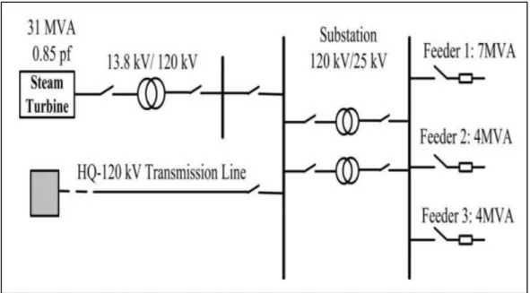
Figure 1.9 Boralex islanding plant at Senneterre Substation-Hydro Quebec, HQ ...33
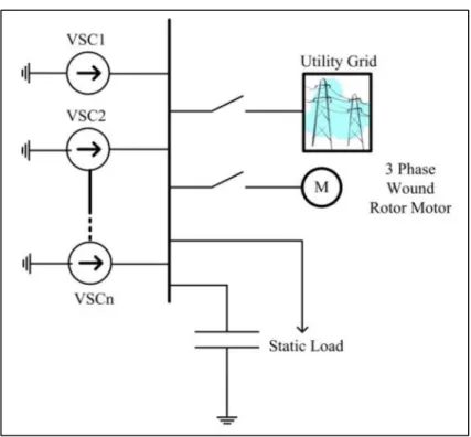
Figure 1.10 Converter fed MG at Toronto ...34
Figure 1.11 Microgrid testbed at Rochester Institute of Technology...35
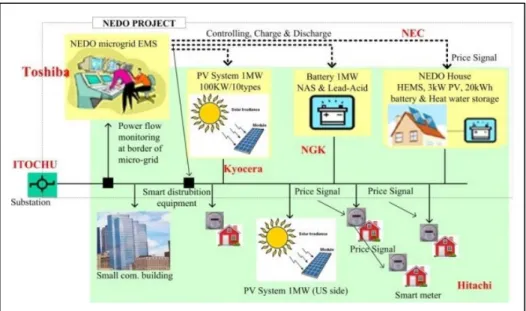
Figure 1.12 Microgrid project at Los Alamos, NM ...36
Figure 2.1 Microgrid system ...37
Figure 2.2 PV cell equivalent circuit ...38
Figure 2.3 Electrical Characteristics of Mitsubishi Electric Photovoltaic Module ...39
Figure 2.4 PV cells configuration in a module ...43
Figure 2.5 PV module configuration in an array ...44
Figure 2.6 DC-DC boost converter ...45
Figure 2.7 Three-phase two-level voltage-source inverter ...48
Figure 2.9 Space vector diagram for the two-level inverter ...52
Figure 2.10 Seven-segment switching sequence ...56
Figure 2.11 PSS and AVR configuration in SG system ...61
Figure 2.12 Governor control: Droop governor (a) and speed regulation (b) ...62
Figure 2.13 Salient Pole Synchronous Machine Model ...63
Figure 2.14 Rotor angular position with respect to the reference position ...71
Figure 2.15 Per-phase equivalent circuit of the three-phase synchronous machine ...71
Figure 3.1 General configuration of the suggested microgrid ...78
Figure 3.2 Power flow between two generators ...79
Figure 3.3 Multi-ratio compensating index...83
Figure 3.4 Three-phase inverter...84
Figure 3.5 Control structure for inverter; frequency loop control ...84
Figure 3.6 Control structure for inverter; terminal voltage loop control ...88
Figure 3.7 Bidirectional DC-DC converter ...89
Figure 3.8 Control structure for battery converter; Voltage loop control ...93
Figure 3.9 Photovoltaic dc-dc converter ...94
Figure 3.10 PV converter control; Maximum power point tracker (MPPT) ...94
Figure 3.11 Flowchart of the MPPT based on P&O method ...98
Figure 3.12 Terminal voltage performances under load increment ...99
Figure 3.13 Active powers; hybrid PV & battery (a), Synchronous generator (b) ...100
Figure 3.14 Reactive powers; hybrid PV & battery (a), Synchronous generator (b) ..101
Figure 3.15 Frequency performance ...103
Figure 3.16 Droop performance p* ...103
Figure 3.18 PV-battery a.c. current; (a) id; (b) iq ...105
Figure 3.19 PV-battery d.c. current ...106
Figure 3.20 Energy performance under load change (a) EDC; (b) s2 ...107
Figure 3.21 MPPT algorithm performance; (a) PV power; (b) PV voltage ...108
Figure 4.1 Microgrid system ...112
Figure 4.2 Exact input-output feedback linearization scheme ...117
Figure 4.3 Simulation results of microgrid frequency (p.u.) ...121
Figure 4.4 Simulation results of microgrid terminal voltage ...121
Figure 4.5 Simulation results in MG islanding mode, active power sharing ...122
Figure 4.6 Simulation results in MG islanding mode, reactive power sharing ...123
Figure 4.7 Simulation results in MG islanding mode, (a) vd, (b) vq ...124
Figure 4.8 Simulation results in MG islanding mode, (a) d-axis current, id , (b) q-axis current, iq ...125
Figure 4.9 Simulation results of MPPT test under insolation ramp changes ...126
Figure 4.10 Simulation results of MPPT performance, control action signal, s1 ...127
Figure 4.11 Simulation results of MPPT performance, battery power during insolation ramp changes ...127
Figure 4.12 Hardware setup of MG system ...128
Figure 4.13 Experimental results in microgrid, synchronization of PV generator to synchronous generator, V 100V/div, 10ms/div ...130
Figure 4.14 Experimental results of microgrid frequency (p.u.), with and without PV participation in MG islanding mode ...130
Figure 4.15 Experimental results of microgrid voltage (p.u.) at AC bus ...130
Figure 4.16 Experimental results, PV/battery generator ac power, p.u. ...131
Figure 4.18 Experimental results, DC bus voltage(V) 200V/div, battery voltage 50V/div, phase current(A) 5A/div and DC current (PV and battery
discharging current)(A) 5A/div 200ms/div.. ...132
Figure 4.19 Experimental results, PV power(W) 100W/div, PV current(A) 2A/div, PV voltage(V) 50V/div 10s/div.. ...132
Figure 5.1 System configuration ...137
Figure 5.2 Robust adaptive exact input-output feedback linearization scheme ...157
Figure 5.3 Load sharing active power; (a) PV/battery active power; (b) SG active power ...159
Figure 5.4 Load sharing reactive powers; (a) PV/battery reactive power; (b) SG reactive power ...160
Figure 5.5 SG regulation; (a) SG terminal voltage , (b) speed regulation ...161
Figure 5.6 Inverter current regulation; (a) id , (b) iq ...162
Figure 5.7 Inverter control action; (a) vd , (b) vq ...163
Figure 5.8 Frequency performance ...164
Figure 5.9 AC bus voltage performance ...164
Figure 5.10 Parameter estimation; (a) , (b) ...165
Figure 5.11 MPPT test; (a) insolation ramp change ...166
Figure 5.12 MPPT test; (a) insolation ramp change (b) PV current (c) PV power ...167
Figure 5.13 Frequency comparison between Robust adaptive Nonlinear Control, Nonlinear Control and classical droop control ...168
Figure 5.14 AC bus voltage comparison between RANLC (Robust adaptive Nonlinear Control), NLC ( Nonlinear Control) and classical control ...169
LIST OF ABREVIATIONS
AC Alternating Current
ANN Artificial Neural Network AVR Automatic Voltage Regulator
EMS Energy Management System
DC Direct Current
DE Differential Evolution
DES Distributed Energy Storage DFIG doubly-Fed Induction Generator
DG Distributed Generation
DQ Direct Quadrature
FA Firefly Algorithm
FLC Fuzzy Logic Control
IC Incremental Conductance
IEEE Institute of Electrical and Electronics Engineers
IM Induction Motor
KCL Kirchhoff's Current Law
KVL Kirchhoff's Voltage Law
MG Microgrid
MIMO Multi-Input Multi-Output
MPPT Maximum Power Point Tracking
PCC Point of Common Coupling
PI Proportional Integral
PLL Phase Lock Loop
P&O Perturb and Observe
PSO Particle Swarm Optimization
PSS Power System Stabilizer
PV Photovoltaic
PWM Pulse Width Modulation
SCM Standard Conditions of Measurement
SG Synchronous Generator
SISO Single-Input Single-Output
SMC Sliding Mode Control
SVM Space Vector Modulation
RE Renewable Energy
LIST OF SYMBOLS Base units
Time s second
Mass kg kilogram
Power w watt
VAR volt-ampere reactive
VA volt-ampere
Voltage V volt
Current A ampere
Angle rad radian
Temperature °C Celsius
K Kelvin
Mechanical units
Friction F Newton/rad/s
Inertia J kgm2
Velocity m/s meter per second
rad/s radian per second
mechanical angular velocity in rad/s synchronous angular velocity in rad/s Acceleration rad/s2 radian per second squared
Angle angular position of the rotor in rad
synchronously rotating reference in rad Torque N.m Newton-meter
mechanical torque in N.m accelerating torque in N.m Irradiance w/m2 watt per meter squared
Electrical units
Velocity electric angular velocity in rad/s Torque electrical torque in N.m
INTRODUCTION
1. Overview
During recent years, the utilization of renewable energy sources has been promoted quickly to fulfill increasing energy demand and to deal with global climate change. Due to growing penetration of renewable energy sources into power grid systems, motivations of studies on advanced control systems are increasing to support voltage and frequency of microgrid (Phadke, Thorp et al.) when significant contingencies occur (Ekanayake, Holdsworth et al. 2003). In the traditional grid-connected mode of microgrid (MG), the changes at output of renewable energy sources (i.e. active or reactive powers) can be transferred to the grid system. In this case, the frequency and voltage are compensated by the grid. Traditionally, microgrids are disconnected from the upstream grid when a fault occurs. In this situation, if active and reactive power generated by renewable sources remain unchanged, it could increase the risk of instability for the entire microgrid especially when the net amount of generated power becomes significant (Mauricio, Marano et al. 2009). The imbalance between generated power and load power causes over frequency or over voltage that can trip off the inverter integrated into MG design.
More particularly, photovoltaic power plants, as one of the most significant family of renewably energy resources, pose important challenges when integrated into the microgrid. Photovoltaic (PV) inverters always focus on extracting maximum power from the PV array system; this makes the PV system unavailable to contribute in regulating the microgrid frequency as compared to the conventional generators (Taheri, Akhrif et al. 2012). The problem of making PV systems have similar behavior as that of the conventional generators remains a big challenge (Datta, Senjyu et al. 2010).
In this context, this research mainly provides advanced strategies of voltage and frequency control for islanded microgrid system in the presence of PV generators. This thesis (i) states the problems that result from integrating PV systems into microgrids, (Saito, Niimura et al.),
(ii) gives a literature review of advanced control methodologies of MG frequency and voltage such as nonlinear, adaptive and robust control, (iii) suggests a nonlinear model of PV/battery generator, (iv) proposes innovative strategies based on improved linear, nonlinear and robust adaptive nonlinear control techniques and (v) finally discusses the results regarding implementing the proposed advanced control using both simulation in Matlab/Simulink and experimentation in laboratory for validation purposes.
2. Motivation of research
Constant growth in global energy demand remains a serious concern between energy and environment. Ideally energy resources that cause no environmental impact must be utilized by a society looking for a sustainable development. However, every energy resource leads to some negative environmental impact. These negative impacts of energy can be in part overcome through increased energy efficiency. In addition, in the electrical energy generation sector, electric utilities are facing other challenges such as rising fuel costs, aging assets, and pressure to adopt renewable portfolio standards. Most of these issues can be overcome without any imperil of overall performance and quality of the power systems. Renewable energies have drawn the most attention in comparison with conventional energy generations in recent years. Among renewable energy sources, photovoltaic as clean, pollution free and inexhaustible energy resource is expected to be one of the biggest contributors of electricity generation by 2050. Figure 0.1 shows a rapidly increasing of the global PV installation during years between 2010 and 2017. In 2010, installation of PV was 20GW while IHS research expects the PV installation to grow up to 61GW by 2017 (Beehler 2008, IHS 2013). Looking further ahead, if the United States of America is to achieve the ambitious target of an 83% reduction in carbon emissions by 2050, this will require that renewable sources contribute at least 50% of the energy used for electricity generation (Eric Martinot 2007). With a rise in the PV penetration and its progress into the global market, PV systems with advanced features to create an efficient economic system are required.
Figure 0.1 IHS Worldwide Photovoltaic Installation Forecast (Gigawatts) Taken from IHS (2013)
3. Problem statement
Generally, a PV system is categorized into stand-alone and grid-connected types. In the global market, a large proportion of power is supplied by the grid-connected type because of its investment saving, high efficiency, convenient topology and simple control strategy (Chunqing, Yong et al. 2009, Lee, Kim et al. 2009).
The problem is that the outputs of renewable generators such as PV and wind generators are enormously affected by weather conditions. In fact, this intermittent power from the renewable sources consequently has some severe impacts on power system operation. Frequent voltage regulation in distribution lines may cause voltage fluctuation which accordingly damages the voltage-regulating devices (ElNozahy and Salama 2013). They also may cause frequency deviation of power systems which depreciate high PV power penetration (Rikos, Tselepis et al. 2008). In fact, the more distributed generation grows the more storage capacity is required. It infers that the spinning reserve for frequency control
also decreases. If renewable energies are to provide a huge amount of microgrid power, they will need to maintain some power in reserve. On the other hand, the sunlight or wind is not always present or predictable. Therefore, a consideration of energy reserve facilities supplementing a virtual spinning reserve seems to be one of the challenges of providing frequency responsiveness and dispatchability to PV or wind systems. In fact, they store power during normal operation and inject power during a fault, to maintain the proper micro grid frequency and voltage. These storage facilities are newly deployed as distributed energy storage (DES). However, they require extra cost and the sophisticated energy management is necessary (Kakimoto, Takayama et al. 2009, Sow, Akhrif et al. 2011,Watson and Kimball 2011).
Another important challenge of current PV systems is that they are not well designed to participate in the frequency regulation of the microgrid when it is affected by large disturbances. Indeed, in conventional power systems, each synchronous generator (SG) could respond to the frequency deviation because of the kinetic energy stored in rotor. However, PV generator doesn’t have this rotating part to provide spinning reserve for frequency regulation. Moreover, the typical concept of maximum power point tracking (MPPT) conflicts with frequency regulation. Unlike the power deloading concept in conventional power system, the MPPT algorithm doesn’t leave any power reserve to compensate the frequency deviation. This results in a significant reduction of the robustness and frequency regulation capabilities under higher PV penetration into microgrid system. As a consequence, the frequency may change abruptly due to disturbances and parameters uncertainties in generation or loads. Therefore, new trends of PV systems in a microgrid require being equipped with an advanced and robust control unit which is able to contribute not only to voltage but to frequency regulation as well (Yan, Jianhui et al. 2011). To be able to achieve high performance renewable sources interacting appropriately with traditional micro power grids, PV systems require reacting like conventional generators, such as synchronous generator. Power network needs these types of renewable generators to support both voltage and frequency regulation. To simultaneously support renewable generators with MPP
tracking and frequency regulating, PV systems should operate in conjunction with storage components to have some power in reserve.
Considering storage devices in parallel with PV systems in a microgrid, the concepts of energy management become necessary. Intelligent mechanisms are required to make PV and microgrid interact properly. On the other hand, control techniques used in conventional PV systems are mainly linear. However, to have PV and storage elements working together, sophisticated switching power electronics devices are required. In the case when the application calls for less power losses or large power transfer, it is necessary to use different types of converters with more power electronics switches. Since the aforementioned system (hybrid PV-battery generator) has severe nonlinear behavior, the use of a simple linear controller is not adequate for such applications and doesn’t provide good performances.
4. Objectives of research
The main objective of this research is to make the PV-battery system behave like a conventional generator e.g. synchronous generator while automatically managing power sharing between different modules using an advanced and innovative control strategy. This minimizes the costs and problems associated with the presence of rotating machines. On the other hand the generated power (active or reactive) by PV-battery system increases when both the MG frequency and voltage decrease respectively due to load demand increment, and vice versa.
Specifically, this research aims to:
• ensure high performance voltage and frequency regulation in the presence of fluctuations and load variations (Objective.1);
• integrate a conventional MPPT to ensure the PV operates at its maximum power point (Objective.2);
• coordinate the power delivery among different units i.e. PV and battery system in a MG without the need for a separate energy management system (Objective.3).
The overall expected configuration of the microgrid system associated with above-mentioned objectives is presented in Figure 0.2.
2
S
inf
L
Figure 0.2 Suggested microgrid system
5. Methodology
To achieve the objectives stated in previous section, this study is structured based on modeling, control design and validation using both simulation and experimental investigation at GREPCI laboratory. The proposed methodology is briefly described below:
First, in order to integrate photovoltaic, battery, synchronous generator using corresponding power electronics converters and isolation transformers into a microgrid and to design a unified controller for this system, a detailed model of the system is required. Hence an accurate and nonlinear multi-input multi-output (MIMO) dynamical model of system is extracted based on mathematical relationship among physical components. This model is used for the design of an advanced control scheme i.e. robust adaptive nonlinear control.
Second, an advanced and innovative voltage and frequency control strategy which is robust, adaptive and nonlinear is proposed via nonlinear dynamics of system. These controllers are designed to drive switching converters such that the perturbation, uncertainty and
nonlinearity of the system as well as power sharing by battery are taken into account in control design. To extract the optimum power of PV generator, a maximum power point tracking (MPPT) algorithm is integrated into the controller.
Finally, validations of the proposed strategy are respectively conducted in two steps; simulation and laboratory experimentation. To implement the proposed control methods, a simulation model (see Figure 0.2) of the proposed system is developed in Matlab/Simulink software. This includes modeling of controllers, PV array, power electronics converters, lead-acid battery, transformer, load and synchronous generator. Some test methods are applied to the simulation model to validate the control performance such as sun insolation variation and load changes. Then, a hardware test bench is developed to verify the effectiveness of control method. This experimental setup includes a PV array emulator, lead-acid battery, synchronous generator, induction motor (IM) developed by Lab-Volt, drive system with speed controller developed by ABB, three-phase transformer, DC-DC converter, three-phase inverter and load. The developed control scheme is programmed and implemented using Texas Instrument TMS320F28335 microcontroller. In fact, the C code generated from the proposed controller through Simulink will be downloaded to the microcontroller board, where it is executed in real time. The system is tested under different scenarios in order to ensure the effectiveness of the proposed control methods such as insolation and load changes.
6. Statement of the originality of the thesis
The lack of a systematic strategy for maintaining the voltage and frequency of microgrid when PV system largely will be used has motivated the present study, which aims at developing an 8th
order dynamical model of the proposed PV-battery system (the first contribution). The novelty of this model is the integration of the nonlinear dynamics of the microgrid frequency, delivering powers and voltages. Using this comprehensive state variables representation, the second contribution of this thesis is the design of unified multivariable controllers based on techniques such as an improved linear, a nonlinear (an exact input-output feedback
linearization scheme) and a robust adaptive nonlinear control for the hybrid photovoltaic-battery source in a MG system. These unique controllers (i) guarantee proper voltage and frequency regulation in the presence of uncertainties, nonlinearities and disturbances (Saito, Niimura et al.), (ii) integrate a conventional MPPT to ensure the PV operates at its maximum power point and (iii) coordinate the power sharing among different units of the PV-battery system.
7. Structure of the thesis
This thesis discusses major topics dealing with contribution of the PV system into the frequency and voltage regulation of the microgrid system, as follows:
Chapter 1 is dedicated to the review of the recent approaches used for modeling, control and
implementation of microgrid with discussion on their specialties and abilities.
Chapter 2 describes thoroughly the full mathematical modeling of the selected configuration
of PV-battery generator in a MG.
Chapter 3 presents the design of the modified linear control for frequency and voltage
regulation in a microgrid including PV, battery system as well as synchronous generator. The method is validated using simulation.
Chapter 4 proposes the design of a nonlinear control, based on exact input-output feedback
linearization for frequency and voltage regulation of a hybrid PV-battery system in parallel with synchronous generator. The proposed nonlinear control is validated using both simulation and laboratory experimentation.
Chapter 5 presents the design of a robust adaptive nonlinear control for frequency and
voltage support by a hybrid PV-battery system in parallel with synchronous generator. The simulation result is included for validation of the proposed system.
Chapter 6 gives the general conclusions of this work and also highlights several
CHAPTER 1 LITERATURE REVIEW 1.1 Introduction
A literature review pertinent to recent methods on the performance of microgrid and its control systems in the presence of renewable energy (RE) generators, in particular, photovoltaic systems are presented in this chapter. Strengths, weaknesses as well as existing challenges of state-of-the-art methods, categorized into the following four general subjects, are well addressed.
First, different types of MG models suggested in literature including linear and nonlinear models are presented. Second, various methods of classical and modern controls with the contribution of photovoltaic generator into frequency and voltage regulation of the MG are described. Third, several conventional maximum power point tracking (MPPT) methods, used to harvest maximum energy from photovoltaic systems, are presented. Last, a set of experimental testbeds of the MG energized by RE resources is discussed.
1.2 Overview of Microgrid Modeling
Different mathematical models have been so far suggested by researchers for a microgrid system with various components consisting of power electronics converters, storage devices, renewable energy sources, conventional generators and loads. The microgrid modeling changes from one structure to another on the basis of used components. This section reviews the main models which have been presented to date under the structure of both linear and nonlinear models.
A first-order transfer function of each microsource in a microgrid consisting of photovoltaic system, wind turbine, fuel cell, diesel engine generator, battery and flywheel storage system is suggested in (Senjyu, Nakaji et al. 2005) as:
= 1 +
(1.1)
where G, T and K represent respectively the transfer function, the time constant and the transfer function gain of the model of each generator. This method introduces a simple approximation of microgrid model commonly for large-scale system and its power flow analysis. The weakness of this method is that the exact dynamics of the system such as power converter modeling are not considered. In other words this model doesn’t represent the real behavior of MG to be used for control design. To address this drawback, a bunch of researches have focused on dynamic modeling of microgird. For example in (Berridge 2010, Karimi, Davison et al. 2010, Bidram, Davoudi et al. 2013), a microgrid structure, consisting of a single DC source connected to a voltage-source converter (VSC) with inductive L filter and passive RLC load, is selected as illustrated in Figure 1.1.
Figure 1.1 Microgrid model Taken from Karimi, Davison et al. (2010)
In these works, the dynamics of MG illustrated in Figure 1.1 is modeled by a nonlinear equation in d-q (direct-quadrature) frame to obtain the standard state space model. The high switching frequency harmonics, considered as disturbance signals, are added to the non-polluted input control signals.
The idea of representing microgrid with a DC source is extended for two generators interfaced in parallel while the passive load is connected at point of common coupling (PCC) (Marwali and Keyhani 2004, Moradi, Karimi et al. 2010, Babazadeh and Karimi 2011). The configuration of this MG is illustrated in Figure 1.2. The nonlinear dynamical equations of microgrid are then obtained by applying Kirchhoffs Voltage Law (KVL) and Kirchhoffs Current Law (KCL) in dq-frame. These models are used for designing the decentralized control where each generator is equipped with a separate controller. In these two previous methods, distributed generators dynamics are neglected by a DC source for the sake of simplicity. Since the dynamics of DGs affect the system performance especially for control design, other studies choose a complete configuration as shown in Figure 1.3.
Figure 1.2 The microgrid structure with two generators in parallel Taken from Babazadeh and Karimi (2011)
The microgrid architecture in (Pogaku, Prodanovic et al. 2007, Nejati, Nobakhti et al. 2013) includes the model of distributed generators such as photovoltaic array, fuel cell and micro-turbine i.e. synchronous generator in addition to the converter models.
Figure 1.3 Configuration of a complete microgrid system Taken from Pogaku, Prodanovic et al. (2007)
In recent years, the contribution of the renewable energy-based generators as of conventional generators to frequency support of a microgrid has taken some attention. Therefore a complete microgrid model including the frequency model supported by renewable energy generators is of interest. In (Sow, Akhrif et al. 2011) authors suggested a nonlinear model of DFIG-based wind generator to contribute to the primary and secondary frequency support of MG. In this work, the rotor speed dynamics are added to the dynamics of inverter to increase inertia of the system. Authors consider a transformer for connecting the DFIG to high voltage system, while the dynamics of transformer and its parameters such as leakage inductance are neglected in the model. The model in this work is limited to a very specific application of wind generator. For other types of RE generators with no rotating part such as photovoltaic arrays, this model is not effective.
Authors in (Okou, Akhrif et al. 2012) suggest a general frequency dynamics for PV application independent of the speed dynamics. In fact the inertia is added by deloading the PV power. The drawback of this approach is that it adds some unknown parameters, such as the equivalent droop coefficient of power system and the time constant, to the MG model. Therefore it needs a modern controller to compensate the uncertainties. In addition there remains a trade-off in meeting both requirements of the MPPT and frequency regulation due to the lack of an actual storage system.
The most recent researches addressed this problem by suggesting Synchroconverters, i.e., inverters that mimic synchronous generators (Zhong 2010, Qing-Chang and Weiss 2011, Qing-Chang, Phi-Long et al. 2014). This model of inverter behaving like a synchronous generator can be used in a traditional power system where a significant proportion of the generation is inverter-based. Similar to the previous method, the model poses several unknown parameters which authors leave the methodology of choosing these parameters and their impact on real power system as a future work. Therefore, this model remains a challenge for control design engineers.
Table 1.1 summarizes the state-of-the-art methods in microgrid modeling in recent years. It presents a comparison of different methods in terms of modeling of power electronics converters, distributed generator, load and frequency.
Table 1.1 MG modeling and analysis
MG modeling method Power converter modeling DG modeling Load modeling Frequency dynamic Modeling type First-order dynamics(Senjyu, Nakaji et al. 2005) × × linear Inverter with DC source(Karimi, Davison et al. 2010) × × nonlinear
Paralleled inverter with DC sources(Marwali and Keyhani 2004) × × nonlinear Inverter-based DGs(Nejati, Nobakhti et al. 2013) × nonlinear Inverter-based DGs with frequency dynamics(Qing-Chang, Phi-Long et al. 2014)
1.3 Overview of MG Control methods
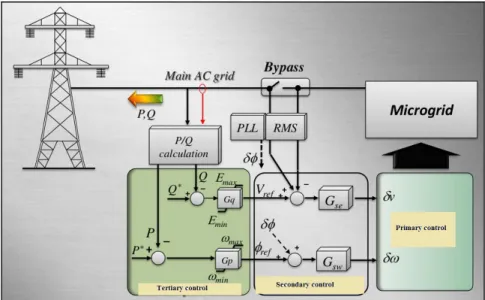
Microgrid control can be classified into three layers as of the primary, secondary and tertiary control (De Brabandere, Vanthournout et al. 2007). The primary layer or field level, which is the main concentration of this thesis, is principally performed on a local control of power converters ensuring frequency and voltage regulation based on the reference signals received. On this layer there is no communication among devices. The secondary layer (Katiraei, Iravani et al. 2008) is responsible for modifying the commanded signals (desired frequency and voltage) to be sent to the primary level control, according to the grid synchronization (via phase locked loop PLL), frequency and voltage restoration techniques. The tertiary control is responsible for dispatching power on the basis of economic and availability of the generators in distribution network operation. On the other hand, the tertiary control task is the management of the importation or exportation of active and reactive power to or from the grid by sending reference signals to the secondary control (Vasquez, Guerrero et al. 2010, Mohamed and Radwan 2011). Figure 1.4 demonstrates the architecture of a typical microgrid control.
Figure 1.4 A typical microgrid control architecture Taken from Vasquez, Guerrero et al. (2010)
Since this PhD work concentrates on MG islanded mode operation, recent primary control approaches in a microgrid with participation of renewable energy generators (i.e. photovoltaic (PV) generator) including frequency and voltage regulation along with MPPT methods are mainly presented in this section.
Frequency and voltage control strategies: A primary control level
In autonomous (islanded) mode, where the microgrid system is not supported by the robustness of the main grid, several works have been carried out on MGs’ frequency and voltage control in recent years. These controllers are categorized into two groups: classical and modern control approaches which are presented as follow.
A. Classical control
The conventional techniques of the voltage and frequency control without the presence of communication protocols are based on droop controls (Chandrokar, Divan et al. 1994, Piagi and Lasseter 2006, Barklund, Pogaku et al. 2008, De and Ramanarayanan 2010). The conventional droop control of MG is based on mimicking the Synchronous Generator (SG) operation. In conventional generator like SG, the measured power, P, is changed by droop control as a function of frequency, P(f). When the output ac power is larger than input mechanical power of SG, the generator slows down due to its inertia. As a consequence, the frequency (and on the other hand the phase angle) at SG terminal lowers. In fact, inverter based MG lacks the inertia. The droop controls in these types of MGs are based on the line characteristics.
The droop control technique in MGs avoids the requirement of complex and costly supervisory system. In addition, the plug-and-play feature of each unit makes the expansion of these systems easier. However, the droop controls have shown some drawbacks such as dependencies on inverters output impedance and trade-off between the accuracy of power sharing and voltage/frequency deviation (with respect to nominal set-points). Some following
modifications of the droop control based on the line characteristics and power flow between buses have been proposed to lessen the effect of these problems. Active and reactive powers (P and Q respectively) flowing between sources ∢ and ∢ with the line impedance Z=R+jX are calculated as (Yun Wei and Ching-Nan 2009):
=
+ [ ( − cos( − )) + sin( − )]
=
+ [− sin( − )) + ( − cos( − ))]
(1.2)
For inductive line impedance with negligible relative phase angle (i.e. = 0, ( − ) small) the above equations are simplified to,
≈ [ ( − )]
≈ [ − ]
(1.3)
Therefore, for inductive network the active and reactive power values are controlled directly by the phase angle and the voltage amplitude respectively. Due to a linear relationship between the angle and the frequency, the frequency is used in control purposes for the sake of simplicity (Phadke, Thorp et al. 1983). Therefore, the generator power is controlled by measured frequency (P(f)). Unlike in SGs where the frequency depends on the rotating speed, in inverter-based MG the frequency is controlled independently. In addition, the power measurement is easier than the instantaneous frequency measurement in microgrid (Arboleya, Diaz et al. 2010). Therefore the drop of frequency as a function of active power is proposed f(P)
where , , and represent the actual and reference of frequency as well as active power respectively. The coefficient is the slope of the frequency droop characteristics. Figure 1.5 shows typical droop characteristics.
Figure 1.5 p-f droop characteristics
Similarly, the voltage amplitude of microgrid terminal is controlled by reactive power such that,
= − ( − ) (1.5)
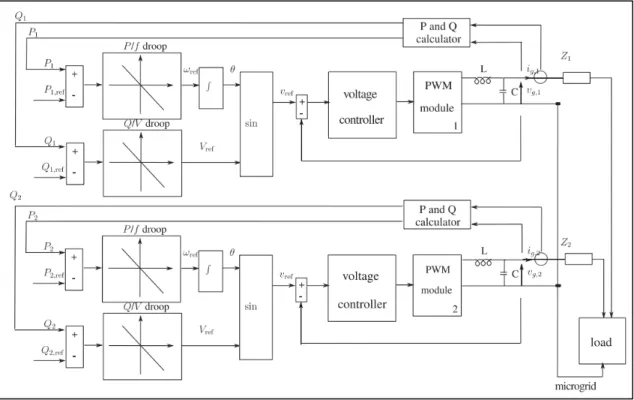
where , , and represent the actual and reference of voltage amplitude as well as reactive power. The coefficient is the positive droop gain. Figure 1.6 illustrates the configuration of the traditional droop control methods based on Q-v and P-f for two VSCs with sharing a common load.
Figure 1.6 Traditional P-F and Q-V droop control methods for microgrid Taken from Hu, Kuo et al. (2011)
In fact, the droop gain is chosen such that to compromise between high gain which causes system instability due to the big frequency/voltage drop in steady state regime and low value gain which increases the settling time. Moreover big load change can vary the frequency/voltage far from its nominal value which reduces the MG stability or even makes it unstable. This approach poses a steady state frequency/voltage drop with respect to load changes (Guerrero, Matas et al. 2006, Guerrero, Vasquez et al. 2011). Despite the droop control being a decentralized control approach, the autonomous power sharing of output power converters are highly dependent on the inverter output impedances (Tuladhar, Hua et al. 2000). These impedances are unknown or vary from each design to another (Lee, Chu et al. 2013). A slow dynamic response of system with conventional droop control is obtained due to the low pass filter which is used for the calculation of average active and reactive powers.
To remove the static error and to reduce the dependency of the conventional droop on the load changes, the integral term is added in previous works (Katiraei and Iravani 2006, Lee and Wang 2008, Haruni, Gargoom et al. 2010, Ray, Mohanty et al. 2010, Jayalakshmi and Gaonkar 2011, Kasal and Singh 2011) as,
= + ( − ) + , ( − ) (1.6)
= + ( − ) + , ( − ) (1.7)
in which, the parameters , and , are the coefficients of the integral terms. To improve the transient response of the system, a derivative term is added to the conventional droop control as, (Goya, Omine et al. 2011).
= + ( − ) + , (1.8)
= + ( − ) + , (1.9)
where the parameters , and , are the coefficients of the derivative terms.This method is effective for a small microgrid with large load change through avoiding large start-up transience (Mohamed and El-Saadany 2008). However, the high derivative gain causes noise amplification in control system. One common approach is to use a washout filter which is in fact a high pass filter ( ) with time constant and derivative gain . Although washout filters have been successfully used in many control applications, there is no systematic way to choose the constants of the washout filters and the control parameters (Hassouneh, Lee et al. 2004). This causes a trade-off between high frequency attenuation (a satisfactory damping using ) and the error of the fundamental components ( , high enough allowing the input signals to pass) (Farahani 2012).
Another problem facing the conventional droop control is the active and reactive power (P-Q) coupling. To overcome this problem a method based on virtual output inductance is proposed.
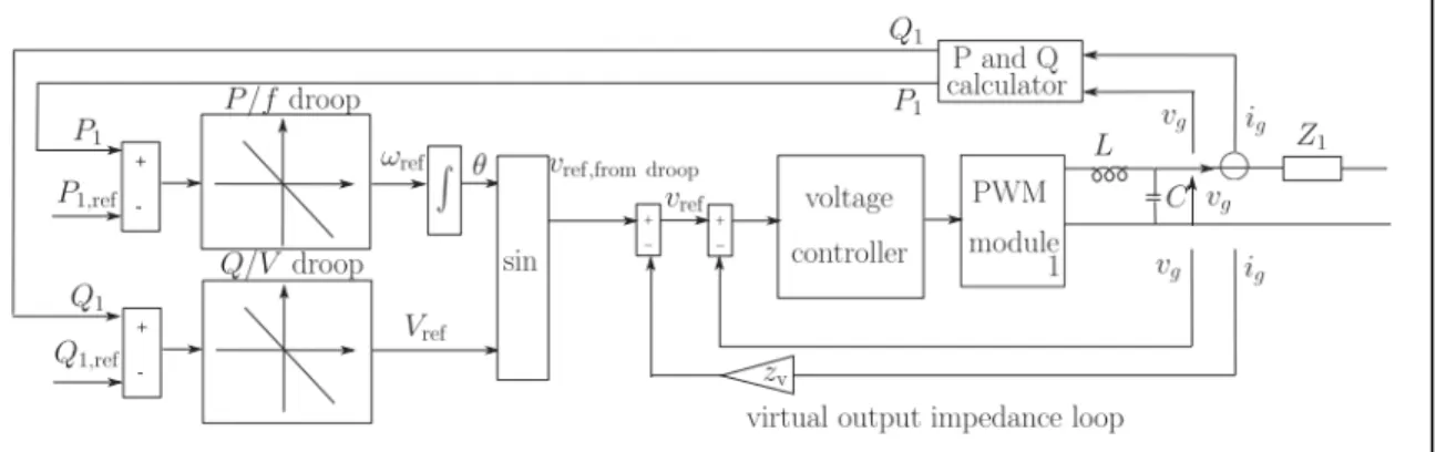
According to Equation (1.3), to have a decoupled droop characteristics, line impedance should be inductive. Therefore, on the control design stage, a virtual inductor is included at the inverter output without the information of line impedance (Funato, Kamiyama et al. 2000, Dranga, Funato et al. 2004). The reference voltage in voltage controller of Equation (1.9) is modified as,
= − (1.10)
where , , , and are the reference and modified reference voltage of the droop control, virtual inductance and line inverter current. Although this method is effective in decoupling the active and reactive powers (He and Li 2011, Cheng, Li et al. 2012, Savaghebi, Jalilian et al. 2012), it causes high frequency noise amplification due to the derivative term as well as reactive power sharing error due to the increased voltage drop as shown in Equation (1.10). In (Yun Wei and Ching-Nan 2009), the reactive power control is enhanced by the estimation of the inductor voltage drop as well as the load estimation. Droop control with virtual inductor control is shown in Figure 1.7.
Figure 1.7 Droop control with virtual inductor control Taken from Cheng, Li et al. (2012)
The previous methods are essentially devoted to the high voltage application of microgrid. In traditional power system with high voltage (Holland, Kirschvink et al.) transmission line where ≫ , the voltage is directly controlled by reactive power and frequency is controlled by active power (conventional P-f and Q-v droop control). However, in low voltage (Vallvé, Graillot et al.) microgrid where the feeder impedance is not inductive, the line resistance should not be neglected (Laaksonen, Saari et al. 2005), because ≫ . In case of resistive line impedance the power flow becomes,
≈ [ − ]
≈ [− ( − )]
(1.11)
Thus the active and reactive powers are controlled respectively by voltage and angle (or frequency) resulting in P-v and Q-f droop control for low voltage MGs (Sao and Lehn 2006, Sao and Lehn 2008, Au-Yeung, Vanalme et al. 2009) as,
= + ( − ) (1.12)
= + ( − ) (1.13)
One of the main challenges of the conventional droop control methods is that the tuning of controller gains as well as system coefficients are not systematic. To avoid the difficult task in finding the controller parameters in previous works, Fuzzy control technique was proposed in (Salhi, Doubabi et al. 2010) to tune the proportional-integral (PI) controller gains according to changes in the system parameters. Similarly a particle swarm optimization (PSO) technique is applied in (Das, Roy et al. 2011) to tune the PI controller gains. However, the online implementation of these approaches is complicated. Fuzzy control needs a trial-and-error process in finding its membership function. In addition, PSO is very dependent on the randomly generated vectors and the initial parameters which their convergences are not mathematically guaranteed.
In addition to the droop control methods, some other researchers suggest different techniques based on deloading power and virtual inertia for the inverter-type microgrid system (Kakimoto, Takayama et al. 2009, Das, Roy et al. 2011). A control method based on simple fuzzy logic was proposed in (Datta, Senjyu et al. 2011) for the PV–diesel hybrid system to introduce the frequency control by the PV and to produce the output power command. Three inputs-frequency deviation (from frequency reference) of the isolated utility, average insolation, and change of insolation- are considered for fuzzy control. A control method based on a load power estimator and an energy storage system is proposed for isolated photovoltaic–diesel hybrid system to provide frequency control. In this method, photovoltaic power is controlled according to the load variation to minimize the frequency deviations. Load power is estimated by a minimal-order observer. Then, a load variation index is calculated. A base photovoltaic power, produced from the available maximum photovoltaic power using a low-pass filter, is added to the load variation index to generate the command photovoltaic power. Since the voltage source inverter along with renewable energy sources (such as PV array generators) are inertia-less, this method of deloading enhances the inertia of the MG system. The weakness of this method is that the maximum power of PV is not always available. On the other hand, PV generator permanently operates below the optimal power to provide a reserve under load power disturbance in order to participate to frequency regulation. The low pass filter used in this design which slows down the system dynamic response is another drawback of this technique.
To increase the inertia and avoid the confliction of frequency and MPPT mentioned in previous publications, frequency regulation in an island and weak power system using large battery energy storage is discussed in (Kottick, Blau et al. 1993). The sole purpose of frequency control is dependent on the battery. In (Li, Song et al. 2008), frequency control was applied to a microgrid consisting of hybrid fuel-cell/wind/PV system. Required power of the electrolyser system is supplied mainly by the wind and PV, and the hydrogen produced by the electrolyser system is stored in the hydrogen tank to be converted back to electricity in the fuel cells. This mechanism emulates storage for the MG system to increase the inertia.
In addition to frequency participation through renewable generator, PV inverters which provide the reactive power to support voltage control have drawn more attention in recent years (Farivar, Clarke et al. 2011, Jahangiri and Aliprantis 2013,Robbins, Hadjicostis et al. 2013). However there are some drawbacks that prevent the PV inverters to support reactive power in order to compensate the voltage. Based on the effective IEEE Std. 1547 the utilities do not accept the PV inverter to inject the reactive power. This conflicts with the unity power factor inverter although the new IEEE standards try to lessen some of these constraints (Basso and DeBlasio 2004). In addition, more expensive oversized inverter reduces the profit of the PV inverter owner. Moreover, the coordination between this type of PV inverter and other traditional inverters is reduced.
In conclusion to the classical control techniques in microgrid design, these model-free control works do not explicitly take into account the nonlinear behavior of MG systems incorporating renewable energy sources and power electronic interfaces. In addition, these linear controllers are not designed to perform uniformly over a wide range of operating conditions or in the presence of nonlinearities, uncertainties and disturbances. Moreover, the different control modules are designed independently. The lack of coordination among the disparate units makes it a difficult task to meet frequency and voltage regulation as well as MPPT requirements. In most applications, a complex and often costly energy management unit is needed. Table 1.2 which summarizes the traditional methods of frequency and voltage control with their different features is presented below.
Table 1.2 Classical frequency and voltage control of microgrid
MG control method MPPT Frequency control voltage control decupling P/Q application
Conventional P-f vs. Q-v droop control (Yun Wei and Ching-Nan 2009)
× HV MG
conventional droop with integral term (Ray, Mohanty et al. 2010)
× HV MG
conventional droop with derivative term (Goya, Omine et al. 2011)
× HV MG
conventional droop with virtual output inductor (Funato, Kamiyama et al. 2000)
× HV MG
conventional P-v and Q-f droop (Sao and Lehn 2006)
× LV MG
Conventional droop P-v with virtual output resistance (Guerrero, Matas et al. 2007)
× LV MG
Modified droop control with soft-computing techniques (Datta, Senjyu et al. 2011)
× HV or LV
MG Power modulation and
virtual inertia control for PV inverter with storage system (Li, Song et al. 2008)
HV or LV
MG
B. Modern control
Among existing modern control methods, those commonly used in power network such as nonlinear control, adaptive nonlinear control and robust adaptive nonlinear control are presented in this section.
i. Nonlinear control
Recently nonlinear control techniques such as sliding mode control, backstepping and input-output feedback linearization have drawn interest in power electronics applications since they offer systematic, powerful and easy-to-implement methods (Marino and Tomei 1996). A nonlinear frequency and voltage control based on backstepping technique is developed for PV generator in (Okou, Akhrif et al. 2012). A multi-input multi-output MIMO nonlinear frequency and voltage control based on feedback linearization technique is developed for doubly-fed induction generators (DFIG) generator connected to synchronous generator (Sow, Akhrif et al. 2011). It is shown in these studies that the nonlinear control approach improves the general system performance in both transient and steady-state regimes since the exact nonlinearity of system is taken into account in control design. The lack of storage system in both techniques causes the renewable generator to operate below its maximum power point, MPP. The effectiveness of these nonlinear control approaches is highly dependent on the system parameters. On the other hand uncertainties in parameters such as load power, terminal voltage of SG, line inductance and SG, PV, DFIG model parameters affects the controller tracking.
ii. Adaptive nonlinear control
The design of adaptive control was introduced in 1950s. The first and most important applications of adaptive control were in mill industries in Sweden. Another important application of adaptive control has been the design of autopilots in flight control. The airplanes operate over a wide range of speeds and altitudes with nonlinear and time-varying dynamics. The different operating conditions of aircraft lead to the different unknown parameters in the system model. A sophisticated feedback control needs to be able to learn about parameter uncertainties. Two adaptive approaches were introduced in the literature; "direct and indirect" adaptive controls. In indirect adaptive control, the plant parameters are estimated online and used to calculate the control parameters. In direct adaptive control, the controller parameters are estimated directly without estimating the plant parameters (Krstic, Kanellakopoulos et al. 1995, Kaufman, Barkana et al. 1998, Åström and Wittenmark 2013).
In a microgrid system with renewable energy integration, the system parameters change due to the load perturbation or the fluctuation in the intermittent power of renewable generator. Moreover there are some parameters in the system model which are unknown. An adaptive control can improve the system performance by estimating the unknown parameters (Yazdani, Bakhshai et al. 2008). Some applications of adaptive control within a microgrid in recent years are listed as: the estimation of the grid frequency in a phase-locked loop (PLL) for active power filtering (Hogan, Gonzalez-Espin et al. 2014), the regulation of the common DC bus voltage with different renewable energy generators (Dragicevic, Guerrero et al. 2014), the adjustment of the weighted coefficients of active power-frequency droop (Li, Wang et al. 2015), the load sharing in a parallel-connected DC-DC converters in a DC microgrid (Augustine, Mishra et al. 2015), the protection and control (Laaksonen, Ishchenko et al. 2014) and the power balance during transition from grid-connected to islanding mode in a microgrid (Shi, Sharma et al. 2013). A nonlinear controller based on sliding mode control with adaptive voltage droop was proposed for a microgrid (Ferreira, Barbosa et al. 2013). The advantage of the adaptive nonlinear control is that it improves system behavior under both nonlinearities and uncertainties. To the best of our knowledge, no research has addressed the adaptive nonlinear control of a microgrid integrated with photovoltaic generators along with storage devices in the literature. Therefore it motivates us to investigate this subject in the next chapters of this thesis.
iii. Robust adaptive nonlinear control
The adaptive laws and control discussed in previous section are designed with the assumption that the plant model is free of noise and disturbance. The designed controller is to be implemented on a practical system that is likely to differ from its mathematical and ideal models. The actual plant can be corrupted by noising measurement or any external disturbance. The discrepancies between the developed and real models may affect the system performance and robustness.
The theory of robust adaptive nonlinear control was first presented by Kokotovic and Marino in 1991 (Kanellakopoulos, Kokotovic et al. 1991). A new robust adaptive nonlinear control based on backstepping scheme for frequency and voltage regulation was designed for DFIG wind turbine (Okou and Amoussou 2008). This strategy takes into account the uncertainty, disturbance and nonlinearity of the system in the control design. However the problems associated with the microgrid lacking the storage system (i.e. MPPT vs. frequency confliction) and inertia-less generators such as PV system (i.e. virtual inertia) are not addressed.
Overview of the recent maximum power point tracking approaches
The low energy conversion efficiency of PV array hinders the widespread use of PV in power systems. In order to overcome this drawback, maximum power should be extracted from the PV system. This objective can be achieved by a MPPT which identifies the optimal operation of the PV systems.
To date, several MPPT techniques have been reported which can be sorted into three categories; namely the conventional, soft computing and advanced model-based methods. Among conventional MPPT methods reported in the literature, the hill climbing (Elgendy, Zahawi et al. 2011, Ahmed, Li et al. 2012, Kumar 2012, Abuzed, Foster et al. 2014), perturb and observe (P&O) (Femia, Petrone et al. 2004, Liu and Lopes 2004, Femia, Petrone et al. 2005, Khaehintung, Wiangtong et al. 2006, Fangrui, Yong et al. 2008) and incremental conductance (IC) (Yuansheng, Suxiang et al. 2012, Guan-Chyun, Hung et al. 2013, Latif and Hussain 2014) are commonly used since they are quite simple to implement and they exhibit a good convergence speed. However, the oscillation around the MPP is the major drawback of theses algorithms (Banu, Beniuga et al. 2013). The oscillatory behaviour around the MPP reduces considerably the system efficiency due to power losses. Moreover, when the atmospheric condition varies, these methods may be confused since the operating point can move away from the MPP instead of working around it. In order to minimize the oscillation, several attempts were made by reducing the perturbation step size. However, a smaller
perturbation size affects the tracking speed adversely (Sera, Mathe et al. 2013, Shah and Joshi 2013).
In order to improve the abovementioned drawback, soft computing (SC) techniques such as fuzzy logic control (FLC) (Ze, Hongzhi et al. 2010, Chin, Tan et al. 2011, Ze, Hongzhi et al. 2011, Arulmurugan and Suthanthira Vanitha 2013, Roy, Basher et al. 2014), Artificial Neural-Network (ANN) (Kaliamoorthy, Sekar et al. 2010, Phan Quoc, Le Dinh et al. 2010, Pachauri and Chauhan 2014), genetic algorithm (Ramaprabha, Gothandaraman et al. 2011, Daraban, Petreus et al. 2013, Hadji, Gaubert et al. 2014, Mohamed, Berzoy et al. 2014), differential evolution (DE) (Taheri, Salam et al. 2010, Sheraz and Abido 2012, Taheri, Taheri et al. 2012), particle swarm optimization (PSO) (Kondo, Phimmasone et al. 2010, Phimmasone, Kondo et al. 2010) and firefly (FA) (Sundareswaran, Peddapati et al. 2014) algorithms have attracted much interest over the past years. One of the distinctive features of the soft-computing MPPT techniques comparing with other MPPT approaches is that they outperform in global searching during partial shading condition in PV system. Despite of their effectiveness, SC algorithms are more highly dependent on the complexity of computing programs (Paul 2013). In FLC MPPT, the membership function is generated through a time-consuming process. One of the major criticisms of ANN MPPTs is that they are considered as black boxes. Therefore no satisfactory explanation of their behaviour is offered. In stochastic techniques the decision variable, either the duty cycle of the power electronic converter or the reference voltage of the controller, is employed by the random vectors during the execution of algorithm. Therefore the global MPP convergence cannot be mathematically guaranteed.
In order to overcome the problems of previous methods, in particular, the oscillatory behaviour and complexity of existing MPPT algorithms, a new trend of MPPTs based on model-based approaches has been suggested in very recent years. Sliding mode controller MPPTs (SMC-MPPTs) (Siew-Chong, Lai et al. 2007, Siew-Chong, Lai et al. 2008, Yan Ping and Fang Lin 2009, Pradhan and Subudhi 2015) possess robustness of tracking control and
stability against internal system parameters and load uncertainties. Adaptive MPPT based on variable scaling factor has been suggested in using proposed small-signal model (Kui-Jun and Rae-Young 2012, Kui-Jun and Rae-Young 2012). Robust adaptive sliding mode control scheme has been developed for MPPT in (MacKunis, Reyhanoglu et al. 2012). Unlike the MPPTs based on soft computing techniques such as DE, PSO, and FA MPPTs which outperform under partial shading condition (the existence of the multiple peaks on PV characteristics), the model-based MPPTs (i.e. nonlinear MPPT controller) suggested in the literature are not ready for PV system exposed in partial shading condition. Therefore these types of model-based MPPTs can be improved for global optimization. The comparison of recent MPPTs is listed in the following table.
Table 1.3 Comparison of MPPTs in PV application
MPPT methods and Criteria Conventional MPPTs (P&O, IC, etc.)
Soft-computing MPPTs (ANN, FLC, DE, PSO, etc.) Modern control (adaptive, SMC, nonlinear MPPTs) Convergence in uniform condition
Yes Yes Yes Convergence in partial
shading condition
No Yes No
Design complexity simple complex moderate
Convergence speed vs.
accuracy very low high high
Dependency on initial parameters
moderate high moderate
1.4 Microgrid testbeds
This section lists the recent development in the industrial and academic microgrid testbeds and example cases as of either remote MG or utility MG supplied by both diesel and renewable DGs for different applications such as military, remote area, uninterruptable power supply, emergency power, electric vehicle and residential application.
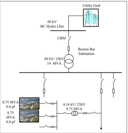
Boston Bar – British Columbia (BC) Hydro, Canada:
Boston Bar substation is connected to BC Hydro grid through a 60Km, 69KV transmission line and a 14MVA transformer. This traditional transmission faces frequent blackouts due to climate conditions. To provide improved reliability on rural feeders, a microgrid with three feeders has been interconnected to the 69KV by a 69KV/25KV substation since 1995. The MG includes two hydropower generators 8.75 MVA, 0.8pf. Although no physical storage system is considered in the design of microgrid, the inertia of generators is enlarged (Peralta, Iosfin et al. 2009). Figure 1.8 demonstrates the configuration of the Boston Bar microgrid.
Figure 1.8 The Boston Bar BC hydro microgrid Taken from Katiraei, Abbey et al. (2008)