Science Arts & Métiers (SAM)
is an open access repository that collects the work of Arts et Métiers Institute of
Technology researchers and makes it freely available over the web where possible.
This is an author-deposited version published in:
https://sam.ensam.eu
Handle ID: .
http://hdl.handle.net/10985/9458
To cite this version :
Georges TOD, François MALBURET, Julien GOMAND, Pierre-Jean BARRE, Benjamin BOUDON
- An Energetic Approach to Aeroelastic Rotorcraft-Pilot Couplings Analysis - In: European
Rotorcraft Forum, Russie, 2013-09-04 - European Rotorcraft Forum - 2013
Any correspondence concerning this service should be sent to the repository
Administrator :
[email protected]
AN ENERGETIC APPROACH TO
AEROELASTIC ROTORCRAFT-PILOT COUPLINGS ANALYSIS
Georges Tod, François Malburet, Julien Gomand, Pierre-Jean Barre and Benjamin Boudon
[email protected], [email protected], [email protected] Arts et Metiers Paristech, Aix-en-Provence, France
Abstract
This paper describes an energetic method using multibond graphs to model multi-physical systems. Its potential in building physical meaningful graphs that represent equivalent mathematical models of classic analytical approaches is shown. An application to the study of an aeroelastic rotorcraft-pilot coupling is studied by analyzing the passive pilot behavior in the cyclic control loop. A rotorcraft in hover flight is simulated and perturbed on its rolling motion axis. Depending on the rotorcraft characteristics air resonance may occur, and the pilot may involuntarily excite the cyclic lever, increasing the rolling motion of the fuselage to an unstable point. Future work will explore eventual alternative solutions to notch filters to avoid passive pilot reinjection at low fuselage frequency modes by controlling for example the actuators of the swashplate through model inversion using the bond graph method.
NOTATIONS
AR Air Resonance
RPC Rotorcraft Pilot Coupling
MBG Multibond Graph
FCS Flight Control System
DoFs Degrees of Freedom
DAEs Differential Algebraic Equations
z Rotorcraft altitude
mf Fuselage mass
b Number of rotor blades
FLift i Lift force provided by blade i
kFCS Constant gain of the FCS
θc Collective pitch
kaero Time invariant aerodynamic coefficient
Multibond graph elements are expressed in three dimensions: power arrows transport one flow and one effort three dimensional vector.
1 Common flow junction
0 Common effort junction
R Damper
C Spring
MSe Ideal modulated source of effort
MTF Modulated power conservative matrix
MTX Cross product matrix
MTA Rotation matrix
1. INTRODUCTION
Rotorcraft dynamics are complex to analyze not only because a large number of subsystems can dynamically interact but also from the multiplicity of physical domains they imply. Since, no matter the physical domain, all the subsystems exchange energy, a different path to building equivalent mathematical models of a physical system than with analytical approaches is to independently model bond graphs of each subsystem and then connect them together with power bonds.
To illustrate this potential, the dynamic behavior of a helicopter prone to Air Resonance (AR) during an aeroelastic Rotorcraft-Pilot Coupling (RPC) event is studied. Concerning AR, the interaction between blade lead lag motions and fuselage pitch and roll motions have been deeply investigated with analytical models such as described by Takahashi and Friedmann in [1] or more recently with a minimalistic number of degrees of freedom by Krysinski and Malburet in [2]. In a recent effort to improve the understanding of the interaction between pilot and aircrafts/rotorcrafts, European research groups such as GARTEUR and ARISTOTEL have led research on rotorcraft pilot couplings. In 2008, the GARTEUR group [3] classified aeroelastic RPCs as phenomena concerning the „passive‟ behavior of the pilot subjected to cabin vibrations of a frequency range between 2 and 8 Hz. Since this range contains the fuselage roll and pitch modes frequencies, one can easily imagine, that at these relatively high frequencies for the pilot, he may not be physically able to control his feedback into the cyclic lever. The result is an involuntary injection of in-plane efforts in the rotor that excite into the non-rotating frame the fuselage; many examples can be found in Walden‟s
extensive US Navy and Marine Corps retrospective [4]; as shown by Walden, this phenomenon concerns not only classic helicopters but also more unconventional aircraft architectures like the V-22 Osprey; and since VTOL technologies tend to more unconventional architectures like Sikorsky‟s X2, Eurocopter‟s X3 and Bell/Agusta‟s
BA609 with lighter and more flexible aircrafts, their proneness to aeroelastic phenomena will still be an area of interest.
Concerning, the passive pilot reinjection, Mayo proposed in [5] a famous transfer function to model the pilot‟s biodynamics in the collective control loop. More recently, in [6], Venrooij and al. showed that the highest levels of
biodynamic feedthrough are measured in lateral
directions. In the present study, RPCs involving these lateral directions are investigated by modeling the interactions of right pilot‟s arm and the cyclic control lever. During a hover flight maintained by the FCS; at a given time, a wind gust is simulated that disturbs the fuselage on its roll axis. Both rotorcraft and pilot models are developed using a multibody approach. An equivalent approach has been proposed by Mattaboni et al. [7]. The rotorcraft multibody model is based on Chikhaoui et al.‟s work [8]. The energetic method used in this paper is based on bond graphs; Paynter [9] imagined them in the late 50‟s and extensive work has been then carried out by Margolis and Karnopp [10]. In the aerospace industry, Granda and Montgomery have shown the potential of scalar bond graphs in building space state systems [11] in application to the analysis of the dynamics of the International Space Station [12]. In this paper, the extension of scalar to vector bond graphs, so called multibond graphs will be used. Actually, they are more adapted to the modeling of multibody mechanical systems undergoing large spatial motions.
The objectives of this paper are, firstly to focus on the energetic method to couple subsystems, which can be multi physical; and show its potential, more than developing new knowledge models. On the second part, it details a model to simulate an aeroelastic RPC event through the cyclic controls in hover flight.
One of the perspectives in the use of multibond graphs (MBG) is to be able to graphically design by model inversion a controller to actively control for example the swashplate actuators and alleviate aeroelastic RPCs.
2. ENERGETIC APPROACH
Basically, in energetic approaches, like bond graphs, one builds a graph in which elements exchange power through multiport junctions; extensive explanations can be found in [13]. The multi physical characteristic of bond graphs is based on analogies on efforts and flows see table 1. In mechanics, each power bond transports an effort that can be a force or an angular moment and a flow that can be a velocity or an angular velocity; power is obtained on each bond by the dot product of the effort vector and the flow
vector. Equivalent mathematical models to classic analytical methods can be obtained (figure 1) by assembling predefined bond graph architectures.
Physical system Physical system
Mathematical Model Multibond graph Direct formulation of equations
Graphical connection of power elements
Analytical approach Energetic approach
Dynamics Analysis Potential interesting level for Dynamics Analysis
Figure 1.The energetic approach
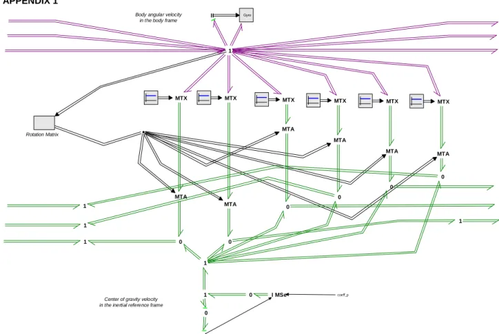
In the case of multibody systems, Tiernego and Bos [14] described the multibond graph architecture of a rigid body, see figure 2a. The architecture they proposed is based on Newton-Euler‟s equations of motion. The movements of the bodies are classically constrained with joints; the architectures of revolute and spherical joints taking into account some flexibility have been detailed by Zeid in [15] and are presented in figure 2b. It can be noticed there is no difference between flexible revolute and spherical joints bond graph architectures; the constraint of degrees of freedom is expressed with a set of springs and dampers. In terms of bond graphs, the two joints are distinguished with the characteristic values of R and C elements. To obtain the bond graph of the multibody system, the rigid bodies‟ graphs are connected to the joints‟ graphs. Once this is set, MTF elements need to be parameterized with geometrical data and the rotation matrices according to desired rotational and translational velocity fields; one does not need to think about the internal efforts between bodies. Finally, eventual external efforts are connected to the graph. The example of the fuselage rigid body can be found in appendix 1.
Table 1.Multiphysics in bond graphs [13]
Energy domain Effort Flow
Translational mechanics Force Velocity
Rotational mechanics Angular moment Angular velocity Electro-
Magnetic domain
Voltage Magnetomotive force
Current Magnetic flux rate Hydraulics Total pressure Volume flow Thermo dynamic Temperature Entropy flow
In order, to illustrate the potential in the vision given by multibond graph representations, a simplified macroscopic symbol of rigid bodies and joints MBG architectures are proposed in figures 2c and 2d. In the macroscopic symbols, the vertices of each figure represent a 0 or 1 bond graph junctions which are the spots where external power can be exchanged.
1 1 1 Se 1 1 1 MTF MTF MTF MTF MGY I I 0 0 0 0 R R R R R R 1 1 1 1 1 1 1 1 1 1 1 1 MTF C C C C C C
a). MBG rigid body b). MBG flexible revolute/ spherical joint
c). Macroscopic MBG rigid body
d). Macroscopic MBG flexible revolute/spherical joint
Figure 2.Multibond graphs of a rigid body and a flexible joint and their simplified macroscopic symbols
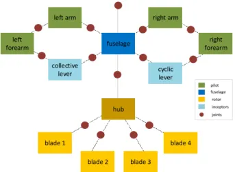
Now, let us consider the multibody model that will be necessary to study the RPC event presented in the next section, see figure 3. The pilot‟s shoulders are supposed to be attached to the fuselage through flexible joints on one side; on the other side they are linked to the collective and cyclic pitch levers. These inceptors are as well, linked to the fuselage through flexible joints.
fuselage hub blade 1 blade 2 blade 3 blade 4 right forearm cyclic lever collective lever left forearm
left arm right arm
joints pilot fuselage rotor inceptors
Figure 3.Pilot-Fuselage-Rotor multibody model
By representing the macroscopic symbols presented in figure 2 under each rigid body and joint, the whole model multibond graph topology can be obtained in figure 4. As a remainder, between each vertices of the resulting figure, power circulates. Many non-obvious power cycles appear and will be analyzed in future work; they will eventually allow analyzing the dynamics of the system without having to run a time simulation.
power cycles
Figure 4.Power cycles to be graphically analyzed
Another interesting feature of energetic approaches is their modularity: each subsystem can be modeled independently and then plugged together at one of the vertices of a more complex model. For example, figure 5, shows the left arm, left forearm of the pilot and the collective lever modeled and simulated offline before being plugged into the complete model. As a result, the degree of detail and complexity of a model can be gradually increased.
Figure 5.Power plugging models
3. APPLICATION TO AN AEROELASTIC RPC
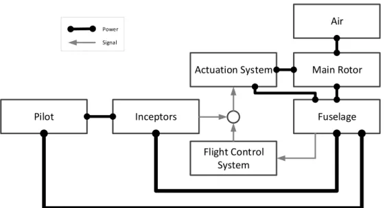
In this section, an energetic model to simulate the pilot-fuselage-rotor interactions is proposed. The method has been defined in the previous section and figure 3 shows the rigid bodies and flexible joints that are taken into account in the following study. Concerning the flight controls, the actuators are supposed to be rigidly attached to the fuselage, see figure 6. The actuators are controlled with the cyclic lever‟s angle information. As a result, it is assumed in this model that the pilot that does not have a force feedback from the rotor. As a remainder, the flight configuration of present interest is a hover flight; the fuselage will be then perturbed, and the dynamic responses of the rotor, pilot and fuselage will be studied.
Pilot
Inceptors
Fuselage
Flight Control
System
Main Rotor
Air
Actuation System
Power SignalFigure 6.Pilot-Fuselage-Rotor model assumptions scheme for aeroelastic RPC simulation
3.1. Bioaeroelastic modeling of a rotorcraft and a pilot
As stated by ARISTOTEL, one of the key problems in tackling RPC for future rotorcraft designs is the lack of adapted pilot and vehicle models; the two can hardly be dissociated [16].
More research efforts have been conducted in fixed wing than in rotary wing concerning the aircraft and pilot interactions. In [17], Lone and Cook propose an extensive review of the pilot modeling techniques. They describe three main categories when it comes to pilot modeling: the human sensory models, the human control theoretic models and the human body models. Our study, concentrates on the last category, and concerns the biomechanical modeling of the two arms of the pilot. Pilot’s passive biodynamics
The arms of the pilot are decomposed into two rigid bodies: forearm and arm. Shoulder, elbow and wrist articulations are considered as flexible joints, see figure 7. The biological characteristics were obtained from literature, see table 2.
Table 2.Pilot’s arm data
Inertia(kg.m²) Mass (kg) Data source
Arms 0,012 1,372
STI, [18]
Forearms 0,015 1,017
Stiffness (Nm/rad) Damping (Nms/rad) Data source
Shoulder 4 0,04 POLIMI, [7] Elbow 3,5 0,035 Wrist 99,1 0,991 Arm Courtesy of Trebor Shoulder 3 elastic dofs Elbow 3 elastic dofs Wrist 3 elastic dofs
Figure 7.Biomechanical model of the pilot’s right arm
When compared to biomechanical pilot transfer function models, like discussed in the introduction, multibody pilot models have the advantage to be more easily adaptable to a specific aircraft cockpit, see figure 8. Therefore, new rotorcraft designers could evaluate the impact of their cockpit designs in terms of RPCs while the cockpit geometry is being defined during the pre-design process. Whereas studying collective bounce, this has probably a reduced impact, since movements are only vertical; it may not, when studying the cyclic control loop. The distance between the elbow of the right arm of the pilot and the aircraft symmetry plane has an effect on the gain between the roll angular acceleration of the fuselage and the tangential effort the pilot introduces in the cyclic lever. The inceptors are modeled following the same logic: collective and cyclic levers are considered as rigid bodies attached to the fuselage through flexible joints.
Forearms
Arms Cyclic lever
Collective lever
Figure 8.Positionning of the pilot in the cabin Aeroelastic rotorcraft and rotor actuation system
The rotorcraft model is based on Chikhaoui et al.‟s work [8] with an extra DoF, the altitude of the fuselage and an original bond graph architecture of the joints between the blades and the rotor hub presented in [19]. The blades are considered rigid and articulated in pitch, flap and elastic lag; this last choice will let the possibility to see the impact of the pilot on the damping of the first lead lag mode. The fuselage can translate in x,y,z directions and rotate around pitch and roll axis. The yaw angular motion is blocked. Basic aerodynamic lift forces are included using the blade element theory.
Flight mechanics and FCS
In the present study, the rotorcraft needs to be trimmed in hover. The role of the FCS introduced in the system is to keep the altitude constant by controlling the collective pitch of the aircraft. At the beginning of the simulation, the initial collective pitch angle is set to compensate for the fuselage weight. However, during the simulation we will disturb the system on the roll axis of the aircraft generating an oscillation of the altitude; since the rotorcraft is already close to a steady state position, we can approximate the aerodynamic lift forces per blade and the dynamic equilibrium of the fuselage,
with, and, ̈ ∑
as a result, ̈ .
Therefore, by sending a collective pitch signal equal to
̈
we can reach the vertical static equilibrium we were looking for.
Mathematical model integration and simulation conditions Concerning the integration of the mathematical model, the usual simulation issues and constraints have to be overpassed. The first one concerns the mathematical model of the pilot‟s arms and levers: these models contain kinematic loops that lead to Differential Algebraic
Equations (DAEs) that are solved using the singularly perturbed formulation for bond graphs proposed by Zeid [20].
To keep a smooth numerical continuity, the degrees of freedom of the fuselage are released one after the other at the beginning of the simulation. The energy provided by gravity and the engine are also gradually introduced in the model.
3.2. Results
The simulated flight configuration is a hover flight; the rotorcraft weights 8 tons and equipped with a 4 bladed soft-in-plane rotor. At t=20s after the beginning of the simulation, a torque step representing a wind gust perturbs the fuselage on its roll axis and the system‟s dynamic response is observed.
The chosen baseline scenario is characterized by a cyclic lever‟s stiffness equal to k=625 Nm/rad and damping c=3Nms/rad. The first simulation shows the pilot‟s feedback in the cyclic control loop, see figures 9 and 10. The pilot‟s right arm plus inceptor and fuselage natural frequency responses are around 3Hz. The cyclic lever oscillates between +/-1°, which correspond to lever‟s top extremity displacements of +/-8mm. The fuselage oscillations are between +/- 0.3°. Figure 10 shows that with the pilot in the loop the roll motion of the aircraft is less damped and the result is an aeroelastic RPC event.
With the pilot in the loop Without the pilot in the loop
Figure 9.Cyclic lever roll angle
With the pilot in the loop Without the pilot in the loop
Figure 10.Fuselage roll angle
20 22 24 26 28 0.020 0.015 0.010 0.005 0.000 0.005 0.010 0.015 Time s A n g le ra d 20 22 24 26 28 0.004 0.002 0.000 0.002 0.004 Time s A n g le ra d
Limiting the pilot’s feedback in the cyclic control loop From the baseline case scenario defined before, some influent parameters are modified and their impact on the stabilization of the roll motion of the aircraft is quantified. In order to visually evaluate the impact of each parameter, one can evaluate how fast the roll motion of the aircraft is damped by looking at the phase portraits presented in figures 12 to 16. All the obtained phase portraits are spiral sinks (fig. 11) and are obtained during the 10 seconds following the impact of the wind gust on the fuselage. Figures 13 to 16 have to be compared to the baseline scenario phase portrait presented in figure 12. The faster the spiral converges towards the origin of the plot, the more the motion is damped: figure 15, shows the worst case scenario, when the additional 30% of stiffness on the cyclic lever baseline lowers the damping of the fuselage roll motion to almost zero. On the other side, by decreasing by 10% the cyclic lever stiffness baseline, the trajectory seems attracted to the origin much more quickly than any other cases, meaning the energy brought by the disturbance to the system is relatively quickly dissipated.
Spiral Sink STABLE Spiral Source UNSTABLE Stable center LIMIT
Figure 11.Fuselage roll trajectory in the phase plane
The cyclic lever gain parameter is the amplitude of the kinematic relation between the cyclic lever angular position and the blades cyclic pitch. Even if this parameter has its importance, lowering it decreases the handling qualities of the aircraft. Another important parameter is the damping of the lead-lag regressive mode by lag dampers - figure 14. Increasing their characteristics may alleviate aeroelastic RPCs occurrences. Since lag dampers characteristics are defined during pre-design phases, the proposed MBG rotorcraft and pilot‟s arms biomechanical model could be useful to alleviate such phenomena in an early design phase.
Figure 12.Fuselage roll angular velocity/angle (baseline)
Figure 13.Fuselage roll angular velocity/angle (baseline -20% cylic lever gain)
Figure 14.Fuselage roll angular velocity/angle (baseline +30% damping and stiffness on blades lag DoFs)
Figure 15.Fuselage roll angular velocity/angle (baseline +30% cyclic lever stiffness)
Figure 16.Fuselage roll angular velocity/angle (baseline -10% cyclic lever stiffness)
0.004 0.002 0.002 0.004 0.10 0.05 0.05 0.10 0.004 0.002 0.002 0.004 0.10 0.05 0.05 0.10 0.004 0.002 0.002 0.004 0.10 0.05 0.05 0.10 0.004 0.002 0.002 0.004 0.10 0.05 0.05 0.10 0.004 0.002 0.002 0.004 0.10 0.05 0.05 0.10
4. CONCLUSIONS AND FUTURE WORK
Energetic methods allow obtaining equivalent
mathematical models to those obtained with classical analytical methods. Their potential in increasing the level of detail of a model by integrating new subsystems has been illustrated. These subsystems can be modeled, tested and validated independently before being power plugged into the global multibond graph of a physical
system. In our case, we could imagine the
complexification of the presented aeroelastic model by integrating literature‟s energetic submodels such as the main rotor‟s suspension [21] and the flight controls [22],[23].
A projection of a dynamic multibody system in the space of multibond graphs was proposed; this vision reveals the presence of power cycles that will be analyzed to
investigate the interest multibond graphs could have in the analysis of dynamic phenomena without the need to run time simulations.
The method was applied to study an aeroelastic RPC, in which the pilot acts in the cyclic control loop of a helicopter during hover flight perturbed by a wind gust on its rolling axis. It will be interesting in the future to cross the simulation results with experimental results and explore the impact of the pilot in the whole flight envelop.
The future pilot‟s models could include the neuromuscular system of the pilot‟s arms. Apart from the originality of the method, future work will also explore alternative solutions to notch filters to avoid passive pilot reinjection at low fuselage frequency modes by for example controlling the actuators of the swashplate through model inversion using the bond graph method.
APPENDIX 1
I Center of gravity velocity
in the inertial reference frame
0 0 0 0 0 0 0 0 1 MTX MTX MTX MTX MTX MTX 1 1 1 1 1 1 I I Gyro MSe I MTA MTA MTA MTA MTA MTA coeff_p Rotation Matrix
Body angular velocity in the body frame
Figure 17.Fuselage body multibond graph model
5. ACKNOWLEDGEMENTS
This work was supported by the “Complex Mechanical Systems Dynamics” project - EADS Foundation - Arts et Metiers Paristech.
6. REFERENCES
[1] Takahashi, M. D. et Friedmann, P., Helicopter Air Resonance Modeling And Suppression Using Active Control. Journal of Guidance, Control, and Dynamics, 1991, Vol. 14, No 6, P. 1294-1300.
[2] Krysinski, Tomasz et Malburet, François. Mechanical
Instability. Wiley-Iste, 2011.
[3] Dieterich, Oliver, Götz, Joachim, Dangvu, B., et
Al. Adverse Rotorcraft-Pilot Coupling: Recent Research
Activities in Europe. In: 34th European Rotorcraft Forum. 2008. P. 16-19.
[4] Walden, R. Barry. A Retrospective Survey of Pilot-Structural Coupling Instabilities in Naval Rotorcraft. In: Annual Forum Proceedings-American Helicopter
Society. American Helicopter Society, Inc, 2007. P. 897.
[5] Mayo, John R. The Involuntary Participation of a Human Pilot in a Helicopter Collective Control Loop. In: European Rotorcraft Forum, 15th, Amsterdam,
Netherlands. 1989.
[6] Venrooij, Joost, Yilmaz, Deniz, Pavel, Marilena D., et
Al. Measuring Biodynamic Feedthrough in Helicopters.
2011
[7] Mattaboni, M., Fumagalli, A., Quaranta, G., et
Al. Identification Of The Biomechanical Behavior Of A
Rotorcraft Pilot Arm.XX AIDAA Congress, Milano, Italy, June 29–July 3, 2009
[8] Chikhaoui, Z., Gomand J., Malburet F., Pavel, M. D. et Barre, P-J., Towards an Energetic Modeling of Rotorcraft Using Bond-Graphs, In : Annual Forum
Proceedings-American Helicopter Society. Proceedings-American Helicopter Society,
Inc, 2013
[9] Paynter, Henry M. Analysis and Design of Engineering
Systems. Mit Press, 1961
[10] Margolis, D. L. et Karnopp, Dean C. Bond Graphs for
Flexible Multibody Systems. Springer Berlin Heidelberg,
1978.
[11] Granda, Jose J. et Montgomery, Raymond C. Automated Modeling And Simulation Using The Bond Graph Method For The Aerospace Industry. In: Proc. AIAA
Modelling And Simulation Technologies Conference And Exhibit. 2003.
[12] Montgomery, Raymond C. et Granda, Jose J. Using Bond Graphs For Articulated, Flexible Multi-Bodies, Sensors, Actuators and Controllers with Application to the International Space Station. Simulation Series, 2003, Vol. 35, No 2, P. 239-250.
[13] Borutzky, Wolfgang. Bond Graph Methodology:
Development and Analysis of Multidisciplinary Dynamic System Models. Springer, 2010.
[14] Tiernego, M. J. L. et Bos, A. M. Modelling The Dynamics And Kinematics Of Mechanical Systems With Multibond Graphs. Journal of the Franklin Institute, 1985, Vol. 319, No 1, P. 37-50.
[15] Zeid, Ashaf et Chung, Chih-Hung. Bond Graph Modeling Of Multibody Systems: A Library Of Three-Dimensional Joints. Journal of the Franklin Institute, 1992, Vol. 329, No 4, P. 605-636.
[16] Aristotel - Eu Project - 'Aircraft and Rotorcraft Pilot Couplings – Tools and Techniques for Alleviation and Detection'
http://aristotel-project.eu/fileadmin/aristotel/public/downloads/aristotel-general_project__presentation.pdf
[17] Lone, Mohammad M. et Cooke, A. K. Review of Pilot Modelling Techniques. In: 48th AIAA Aerospace Sciences
Meeting Including The New Horizons Forum And Aerospace Exposition, Number Aiaa-2010-297, Orlando, Florida. 2010.
[18] Jex, Henry R. et Magdaleno, Raymond E.
Biomechanical Models for Vibration Feedthrough to Hands and Head for a Semisupine Pilot. Aviation, Space, and
Environmental Medicine, 1978, Vol. 49, No 1 Pt. 2, P. 304.
[19] Tod, G., Malburet, F., Gomand, J., Barre, P-J., Modeling Flexibility in Rotational Degrees of Freedom Using Multibond Graphs, iNacomm 2013 Conference Proceedings, to be published
[20] Zeid, Ashraf A. et Overholt, James L. Singularly Perturbed Formulation: Explicit Modeling Of Multibody Systems. Journal of the Franklin Institute, 1995, Vol. 332, No 1, P. 21-45.
[21] Boudon, B., Malburet, F., Carmona, J-C., Tod, G., Modeling MGB-Fuselage joint on helicopter with an energetic approach «multi-bond graph », MBD 2013 [22] M. Martin, J. Gomand, F. Malburet, P.J. Barre, Modelling and Control of a Complex Multi-physic System Application to Helicopter flight axis control, European Modelling Symposium on Mathematical Modelling and Computer Simulation, 2012
[23] Z. Chikhaoui, J. Gomand, F. Malburet, P.J. Barre, Complementary Use of BG and EMR Formalisms for Multiphysics Systems Analysis and Control, ASME-ESDA 2012, Proceedings of the 11th Biennial Conference on Engineering Systems Design and Analysis, 2012.
Copyright statement
The authors confirm that they, and/or their company or organization, hold copyright on all of the original material included in this paper. The authors also confirm that they have obtained permission, from the copyright holder of any third party material included in this paper, to publish it as part of their paper. The authors confirm that they give permission, or have obtained permission from the copyright holder of this paper, for the publication and distribution of this paper as part of the ERF2013 proceedings or as individual offprints from the proceedings and for inclusion in a freely accessible web-based repository.
![Table 1.Multiphysics in bond graphs [13]](https://thumb-eu.123doks.com/thumbv2/123doknet/7337544.212102/3.892.453.814.830.957/table-multiphysics-in-bond-graphs.webp)