Science Arts & Métiers (SAM)
is an open access repository that collects the work of Arts et Métiers Institute of Technology researchers and makes it freely available over the web where possible.
This is an author-deposited version published in: https://sam.ensam.eu Handle ID: .http://hdl.handle.net/10985/9279
To cite this version :
Ahmed Jawad QURESHI, Jean-Yves DANTAN, Jérôme BRUYERE, Régis BIGOT - Set-based design of mechanical systems with design robustness integrated - International Journal Of Product Development - Vol. 19, n°1/2/3, p.64 -89 - 2014
Any correspondence concerning this service should be sent to the repository Administrator : [email protected]
Set-based design of mechanical systems with design
robustness integrated
A.J. Qureshi*
School of Mechanical & Systems Engineering, Stephenson Building,
Newcastle University,
Newcastle Upon Tyne, NE1 7RU, UK Email: [email protected] *Corresponding author
Jean-Yves Dantan
LCFC, Arts et Métiers ParisTech, 4, rue Augustin Fresnel,57078 Metz Cedex 3, France Email: [email protected]
Jérôme Bruyere
LaMCoS UMR5259, Université de Lyon, CNRS, INSA-Lyon, F-69621, Villeurbanne, France Email: [email protected]Régis Bigot
LCFC, Arts et Métiers ParisTech, 4, rue Augustin Fresnel,
57078 Metz Cedex 3, France Email: [email protected]
Abstract: This paper presents a method for parameter design of mechanical
products based on a set-based approach. Set-based concurrent engineering emphasises on designing in a multi-stakeholder environment with concurrent involvement of the stakeholders in the design process. It also encourages flexibility in design through communication in terms of ranges instead of fixed point values and subsequent alternative solutions resulting from intersection of these ranges. These alternative solutions can then be refined and selected according to the designers’ preferences and clients’ needs. This paper presents a model and tools for integrated flexible design that take into account the manufacturing variations as well as the design objectives for finding inherently robust solutions using QCSP transformation through interval analysis. In order to demonstrate the approach, an example of design of rigid flange coupling with a variable number of bolts and a choice of bolts from ISO M standard has been resolved and demonstrated.
Set-based design of mechanical systems
Keywords: set-based design; robust design; QCSP; quantifier; manufacturing
uncertainties; design automation; simulation-based design; design space exploration.
Reference to this paper should be made as follows: Qureshi, A.J., Dantan, J.Y.,
Bruyere, J. and Bigot, R. (2014) ‘Set-based design of mechanical systems with design robustness integrated’, Int. J. Product Development, Vol. 19, Nos. 1/2/3, pp.64–89.
Biographical notes: A.J. Qureshi is a Lecturer at Newcastle University, UK.
He obtained his Bachelor degree in Mechanical Engineering from UET Lahore, Pakistan. In 2007, he obtained Master degree in ‘Design, Industrialisation and Innovation’ from Arts et Métiers ParisTech, Metz, France, with specialisation in Tolerance Optimisation and his PhD in 2011 in the area of robust design in mechanical product design. His research interests are design methodology, robust design, design automation, tolerance analysis, and model based design. Jean-Yves Dantan is Professor at ‘Arts et Métiers ParisTech Metz’ since 2010. He obtained his Master of Science in Manufacturing and Industrial Engineering from ‘Ecole Normale Supérieure de Cachan’ (LURPA) in 1996, his PhD from University of Bordeaux in 2000 and his Habilitation thesis from ‘Ecole Normale Supérieure de Cachan’ in 2009. His research interests include integrated product and process design, tolerancing, uncertainty management and CAPP. He has published around hundred papers and communications. He is CIRP member since 2011, the co-chairman of a National Research Group on Tolerancing (since 2009 with Prof. Alex BALLU), and the coordinator of “Masters of Science” for the Department of Design & Production engineering of Arts et Métiers ParisTech.
Jérôme Bruyere defended his PhD on the geometrical design and tolerances of forged bevel gears in 2006 at ‘Arts et Métiers ParisTech’ (Engineering University). In 2008, he became a Lecturer at INSA Lyon and since then, he has been working on mechanical transmissions at LaMCoS with Professor Ph. Velex. His research is mainly focused on the numerical and analytical optimisation gear tooth shapes with and without geometrical defects and statistical scatter.
Régis Bigot received his MEng degree in Mechanical Engineering from the Ecole Nationale Supérieure d’Arts et Métiers in 1992. In 1993 he obtained a Master of Sciences in Physics and Chemistry of Materials from University of Lille and his PhD degree in Physical and Metallurgy from the University of Lille in January 1996. After three years as technical teacher at Lille and Metz, he joined an associate professor position at the Ecole Nationale Supérieure d’Arts et Métiers in September 1998. In September 2008, he becomes full professor in same institute. Since October 2011, he is Director of Design, Manufacturing Engineering and Control Laboratory. His current research focuses on the manufacturing process (bulk forming, thixoforming, assembly, etc.), integrated product and process design and CAPP.
This paper is a revised and expanded version of a paper entitled ‘Set based robust design of systems - application to flange coupling’ presented at the ‘CIRP Design Conference 2010’, Nantes, France, 19–21 April 2010.
1 Introduction
Product design can be viewed as an issue of information processing in which the information that characterises the needs and requirements for a product is converted into knowledge about a product (Mistree et al., 1990). One of the challenges that the designers deal with in the product design is a lack of detailed information. At the start of the design process, less is known about the design problem at hand. Throughout the progression of the design process, the information about the design problem and the knowledge of the associated design space is increased. This allows a fundamental understanding of the design space and thus guides the designers towards the solution. According to Gericke and Blessing (2011), most design processes can be shown to have a generic core of stages which are: establishing a need, analysis of task, conceptual design, embodiment designs, detailed design and implementation phase. The process progresses through these stages in an iterative manner. At each of these stages, the product design exists within a distinct level of the available information which is called a ‘design state’ (Eisenbart et al., 2011). As this information passes through the stages, it is punctuated by decisions which cause the information to be processed towards the eventual final state where it represents the design solution. The design process progression at any point therefore is dependent on the information generated in the earlier phases as well as the decision making that has preceded the stage.
The decision making often results in reduction of the design space, i.e. focusing on a specific solution, discarding the competing solutions and reducing the design space. If the decision-making results in the selection of a distinct solution without much flexibility, important information regarding the design state can be lost. Designing through such practice is known as point-based design (Sobek et al., 1999). In case of downstream modification, the point-based design results into costly delays and reworks. In addition, it limits the flexibility of the design thus rendering the design more rigid and less likely to adapt to future evolution during the design phase as well as it is potential for future variants.
The approach presented in the paper is based on the principles of set-based design and relates to the domain mapping stage of the set-based design. Relying on the set-based design approach objectives, it provides robust solutions of mechanical systems. This is achieved by using the quantifier notion from QCSP and interval arithmetic to perform design space exploration and separate the admissible design solution spaces containing the robust solutions from initial design space. The approach permits taking into account the design parameters and uncertainty variables associated with the design of a mechanical system in forms of sets, as well as the simultaneous integration of different design stakeholders (design and manufacturing) in the design space exploration. The integration of uncertainty within the design space exploration results in inherently robust solutions. An algorithm has been developed which treats the example of a rigid flange coupling design with ISO standard screws and demonstrates the approach.
The rest of the paper is divided into five sections. Section 2 provides an introduction to the decision-based perspective towards design. Section 3 describes the design task (in redesign and adaptive design problems) from a mathematical point of view and proposes the required model for the set-based robust design. Section 4 deals with the development of the algorithm for the application of the developed method. Section 5 demonstrates the application of the developed methods using the algorithm developed in Section 4. Sections 6 and 7 are dedicated to the discussion and conclusion, respectively.
2 Decisions in product design
Decision-based Design (DBD) is a perspective in engineering design which emphasises and defines the design process from a decision-making viewpoint. DBD emphasises that the design process is primarily a decision-making process based on a succession of decisions based on the available information (McDowell et al., 2010). These decisions transform the information during the progression of a design process from initiation to completion. The decisions represent a unit of communication within and across the disciplines, they may be hard or soft, subject to quantitative or qualitative information on which they are to be based and they may involve making a choice between a number of possibilities taking into account a number of measures of merits or attributes (Mistree et al., 1990).
Taking the broad definitions of decisions as defined above, two types of decision-making processes can be distinguished based on the manner in which the information is selected: the point-based design and the set-based design.
2.1 Point-based design
The point-based design is generally a prevalent design approach in which the design process advances through states known as points. Each point represents a decision point in the design process and results in design improvement and retention of the best design at that point. The information at that point is then transferred to the downstream functions of the next design stage. Generally, both algorithmic and iterative design approaches use successive evaluation loops and hit & trial methods to reach a point-based design in which a given solution is selected to be developed into further detail. The other parallel alternatives at that point are discarded in favour of the chosen concept (Uebelhart, 2006). In practice, the point-based design starts from an initial seed in the design space which is being evaluated for the solutions. Often this point is based on the opinion of the expert design managers or derived from points in the design space known to be a solution. Once a point is identified as a solution, it is then optimised, step by step, with each step moving to a more desirable point in the design space. Through this process the designer attempts to find the most feasible point in the design space in terms of design requirements.
The point-based approach bears some advantages and disadvantages. One of the advantages is that it helps in narrowing down the design space early in the design process and thereby brings a convergence towards a given solution rapidly. On the other hand, the disadvantage of the approach is that at every point, vital information regarding the alternatives, the flexibility in terms of sets of possibilities is discarded, resulting in increasing rigidity in the design as it advances. This often results into high cost in case of a modification in downstream design phases. It also decreases the change management capability within the design process at a later stage resulting in the loss of the process pro-activity. Also, a change made by one member of the team is likely to produce changes on others, these in turn producing more changes, in a chain reaction. There is no fundamental reason for the ensuing change process to ever converge (Chang and Ward, 1995). Developing a project on point-based design therefore is a poor design practice. Use of such deterministic methods may result in systems which are expensive, inefficient and vulnerable to uncertainty and variability. In order for a design to be successful, such deterministic approaches should be replaced with new approaches that use rigorous models to quantify uncertainty and assess reliability (Nikolaidis et al., 2008).
2.2 Set-based concurrent engineering
The set-based concurrent engineering is an approach popularised by a Japanese automobile manufacturer. In this approach, instead of taking a point-based design approach, the designer takes a set-based approach towards design and treats sets of design alternatives at both the conceptual and parametric design levels. These sets are gradually refined and narrowed through the process of elimination of ill-suited alternatives until the emergence of the final design (Ward et al., 1995). In contrast to the point-based design, where one design is refined, the Set-Based Concurrent Engineering (SBCE) maintains the alternatives until the emergence of the final design.
Malak et al. (2009) define the set-based design as an approach in which different design alternatives are evaluated by reasoning and comparing different solutions based on possibilities offered by alternative possible configurations of ‘SETS’ of design parameters. Set-based design aims at delaying commitments to a particular design in favour of gathering information about the problem and reduce imprecision to levels at which indeterminacy is resolved.
The process of SBCE starts with feasible regions which are communicated in form of sets of information. This information is then processed by finding intersections between the sets communicated through the application of constraints. The constraints narrow down the design space. Multiple alternatives are considered and evaluated during the process for feasibility before a commitment is made. Any solution to be committed should be robust to physical, market and design variation (Sobek et al., 1999).
A body of research exists describing both the process and philosophy of the set-based design and the tools and methods employed to carry it out. The term set-based design itself has been coined by Finch and Ward (1997), in his work they presenting a catalogue-based design of mechanical systems using sets. This method narrows the design space by elimination, but does not provide a framework for decision making within the feasible space. Ward and Sobek present the theoretical and philosophical basis of set-based design and its application in the automobile industry as a practice (Liker et al., 1996; Sobek et al., 1999; Ward et al., 1995). Simpson et al. (1996) utilise techniques such as Response Surface Method (RSM) and Taguchi’s method to implement a set-based key parameter design for an aircraft. This work relies on RSM techniques to narrow down the design domain. Finch and Ward (1997) develop and implement an inference method for set-based design of electronic circuits based on quantified relations (QRs), to explicitly represent casual relationships between variables in engineering systems, and present an Interval Propagation Theorem (IPT). They propose an algorithm that propagates intervals through QRs involving continuous and monotonic equations. This approach presents greater flexibility in comparison to the Labelled Interval Calculus (LIC) approach presented by Ward.
Yannou et al. (2003, 2009) use constraint programming techniques over reals for set-based dimensional design of mechanical systems while considering the sets of product key parameters. These methods however do not take into account simultaneous manufacturing variations. Also, a specific syntax and framework for describing the interactions among the parameters does not exist. Yvars (2008) proposes a constraint satisfaction-based design method for design of a coupling system which takes into account a range of design parameters instead of point values and returns the result via calculation through a third party constraint solver.
Sébastian et al. (2007) and Chenouard et al. (2009) present an application of the set-based design process through the numerical constraint satisfaction problem in conjunction with constraint explorer software and heuristic techniques. They determine the set of solutions for key parameters of engineering design problem. The problem is demonstrated with examples of heat exchanger, and aircraft air-conditioning system with consideration of piece wise constraints. The problems presented however do not independently treat the noise and uncertainty arising from independent sources such as manufacturing variations.
Bordeaux and Monfroy (2006) propose the theoretical basis for solving the problem of quantified variables, i.e. variables with existential and universal quantifiers, enabling us to address the sets of values instead of point values for the problems where constraints are arbitrary relations over finite domains. Adopting the viewpoint of constraint-propagation techniques for CSPs, they provide a theoretical study of this problem and propose quantified arc-consistency as a natural extension
Considering the body of research presents in the field of set-based design, research can be divided into the sub-categories of: theory of set-based design, methods and tools for set-based design, and frameworks of set-based design. A significant body of research is available on the theory and tools for key parameter design of mechanical systems and the general philosophy of set-based design applied to the mechanical industry. Similar applications in the domain of artificial intelligence exist as well. However, little work is presented in the domain of formalisation and structuring of a framework applicable to a generic design model. Also, the approaches considered in the literature use set-based parametric design but do not simultaneously address the variations arising from other factors. Currently, this analysis is carried out in the downstream activities via the use of different robust design techniques. The integration of the variations from other factors would result in a set-based design which is insensitive to the variations in the parameters as well as the variations from external sources.
2.3 Set-based robust design
The main objective in the robust design of a system is to design it in such a way that its performance is not compromised beyond the minimum requirements in the presence of variations and uncertainties. Robust design as described by Chen et al. (1996) is a process to de-sensitise the final design towards variations. These variations may be due to the uncontrollable environmental factors or both the uncontrollable factors and the variation within the design parameters (Chen et al., 1996).
The robust design methodology was popularised by the work of Taguchi and Phadke during the 1980s and 1990s who established robust design as a prime methodology for improving the quality and performance of the products. The techniques proposed by Taguchi rely on the formulation of quality loss function and utilisation of design of experiment to evaluate the sensitivity of the performances taking uncertainties into account (Taguchi et al., 2005; Yannou et al., 2009). Using this approach, the integration of robustness takes place as a downstream function in the design process. Once, the design parameters have been selected, the different techniques and methods mentioned above are employed to evaluate the robustness of the design. Based on these results, the design parameters are adjusted to the new values to integrate the robustness in design. This process is therefore remarkably similar to the point-based design methodology as explained by Sobek et al. (1999).
There is no research work that provides a structured framework along with necessary methods and tools to carry out integrated set-based design of mechanical systems with robustness considerations within the parameter design phase. The approach presented in the paper addresses this issue and proposes a design method which eliminates the need for downstream robust design activities; thus resulting in a set-based robust design approach. The method is applicable to quantitative design activities especially in parametric design. It diverges from the statistical and probabilistic methodology. Instead, it relies on set-based concurrent design process discussed earlier and takes into account the notion of uncertainty to ensure robustness. The following section discusses the mathematical formulation of the set-based robust design.
3 Problem formulation
A review of the literature on mathematical modelling of parametric design reveals a common perception towards a constraint satisfaction problem which can be generally modelled in the form {V,D,C} where V is a set of variables, D is the set of domains for V and C is the set of constraints imposed. S is defined as a set of solutions such that for each member of si ∈ S all the variables of the set V have values in D and satisfy the set of constraints C (Lewis and Mistree, 1998; Thornton, 1996; Yannou et al., 2003; Yvars, 2008; Yvars, 2009).
The set of variables V includes all the variables associated with a design problem. Unique values of these variables propose a unique solution for the given design problem. The set of domain D constitutes the space of domains of all the variables in the set V such that for each variable vi ∈ V, there is as corresponding domain di ∈ D, which describes the starting search space for the variable vi. The set of constraints C includes all the constraints resulting from the translation of the client requirements into corresponding functional requirements and their further translation in terms of fundamental mathematical relations governing the design of the product. Each ci is a constraint in the form of a relation between the variables.
For a point-based parametric design solution, the goal is to determine the proper values for the design variables which satisfy the design constraints. The design variables may be of the geometric nature, engineering nature or manufacturing nature and may deal with shape, configuration, material, manufacturing process, etc. The design constraints are generally expressions consisting of the design parameters, constants and variables. In an engineering model, the representation of constraints may be algebraic equations or predicates, sometimes with a few additional logical constraints (Beyer and Sendhoff, 2007). Many engineering design software packages now have some sort of built in support and features to aid the designer by integrating the constraints satisfaction subsystems within the software (Thornton, 1996).
Constraint satisfaction using traditional methods as a standalone technique or in conjunction with other downstream optimisation tools is pertinent in the case of deterministic design. A solution to a CSP generally seeks to identify the discrete point values or instances of research domains to evaluate a solution which satisfies the constraints. A set of these instances calculated in an iterative manner allow us to develop the final solution in terms of valid intervals which satisfy the constraints. This approach is feasible for the point-based design. In case of the management of the uncertainty and robust design, as discussed earlier (integration and unification of variation and uncertainty management within the parameter design), a gap exists in the expression and
formalisation of variable interaction. In terms of a set-based design, a need arises for an approach that can process the information in the form of sets. Standard CSP solutions lack the capability to express the relations between parameters and variations and uncertainties that affect them. This requires the need to separately quantify the variables existentially or universally.
To address this gap, we extend the existing research in the domain of the variable quantification in tolerancing for mechanical assemblies (Dantan and Qureshi, 2009; Dantan et al., 2005). These works provide an example of variable quantification and expression for the problem of variation management in tolerancing. They are based on the existential and universal mathematical quantifiers.
The work presented in the paper utilises the expressive power of the quantifiers and generalises the CSP model to a Quantified Constraint Satisfaction Model (QCSP) for a set-based robust design method. The proposed method can accommodate the variation and uncertainty in the design parameters as well as quantified intervals of uncertainty from sources such as manufacturing and material uncertainties.
3.1 Quantified constraint satisfaction for set-based robust design
The Quantified Constraint Satisfaction Problem (QCSP) is a general extension of the Constraint Satisfaction Problem (CSP) in which variables are totally ordered and quantified either existentially or universally (Chen, 2004). This generalisation provides a better expressiveness for modelling problems by allowing the universal quantification of the variables. For each possible value of such variables, the values have to be found for remaining, existentially quantified, variables so that all the constraints in the problem are satisfied. The QCSP can be used to model PSPACE-complete decision problem from areas such as planning under uncertainty, adversary game playing, and model checking (Gent et al., 2008). QCSPs find their application in the fields from video game design to manufacturing problems.
A standard definition of QCSP as defined by Gent et al. (2005) follows: Definition (QCN): A QCN is a formula QC in which:
• Q is a sequence of quantifiers Q v1 1, ....Q vn n where each quantifier Qi
(
∀ ∃or)
quantifies, a variable vi and each variable occurs exactly once in the sequence. • C is a conjunction of constraints
(
... c1∧ ∧ck)
where each ci involves somevariables among
(
v1, . . . , .vj)
Definition (QCSP): A QCSP is the problem of the existence of a solution to a QCN. The research in QCSP is recent. Bordeaux and Monfroy (2006) have extended the notion of arc consistency of CSP to the QCSP. Mamoulis and Stergiou (2004) defined an algorithm for arc consistency for QCSP for binary constraints. Dantan and Qureshi (2009) proposed the integration of QCSP and quantifiers in the domain of product design by solving the problem of product assembly, tolerance analysis and tolerance allocation for mechanical assemblies with QCSP (Dantan and Ballu, 2002; Dantan et al., 2005).
Based on the principles of set-based design, quantifiers and QCSP, we now propose a general theory of set-based parameter design with variation and uncertainty management.
3.2 Design model
Using the mathematical model of the design mentioned in the earlier section, in order to integrate the general design problem with help of QCSP, we quantify the design parameters and add the uncertainty parameters. Therefore, the new system that emerges can be described as:
{
QV QN D C, , ,}
(1)where
QV = Quantified design variables QN = Quantified uncertainty variables. D = Domain of the variables
C = Constraints governing the variables.
The emerging system can now be formalised mathematically to a robust solution. A brief description of terms is given in order to illustrate the following example.
• Design parameters ‘vi’ are the key design variables having an appreciable effect on the product performance and functional characteristic. These parameters maybe of a mechanical or geometric nature.
• The noise variables ‘nj’ are the variables which model the uncertainty in the product design. These parameters are the measure of the uncertainty of different factors, which might impact the product performance and therefore the conformity of the product performance to the desired design basis.
The formulation, the model and the processing of the noise variables is the same as the uncertainty of the design variables. The domain D includes the domain of the design variables as well as the domain of the uncertainty variables. Once these parameters have been defined, a model needs to be defined which embodies the relation between the product functional requirements, design basis and the above defined parameters. This is done with the help of an analytical model the system while taking into account the design as well as the noise parameters. The model containing equations or inequalities may in general be described in the following form:
• f(vi, nj) is a function which defines the relationship between the desired product performance, the design parameters and the noise parameters.
Some examples of this formulation are presented in Section 4.
3.3 Conditions for solution
In order for a solution to be robust, it should respect the two fundamental conditions concerning the design parameters as well as the noise variables.
3.3.1 Condition for existence of a solution
For any design solution that satisfies the needs of a given design problem, the first condition is the ability to satisfy the functional requirements. In terms of a product model, it means that the solution is able to satisfy the fundamental constraints imposed by the translation of the functional requirements. These constraints are often the thresholds which define the success or failure of the product.
In terms of the proposed mathematical framework, this translates in terms of set-based design evaluating if there exists a successful intersection of sets from different stake holders allowing converging towards a robust solution. Therefore, a solution may be a valid solution if:
‘At least one configuration of design parameters belonging to their respective domains must exist such that the functional requirements are fulfilled’.
It can be written mathematically as: :
V
V D V C
∃ ∈ ∈ (2)
where V is the set of the design parameters belonging to its respective domain DV.
3.3.2 Condition for existence of a robust solution
The robust design aims to ensure that the product performance remains acceptable under the influence of variations. Therefore, the second condition deals with the expression and evaluation of a solution that is robust. It is necessary to quantify the design variables in a way that in spite of the variation in their values, the constraints are satisfied. For this purpose, other sources of variation such as manufacturing variations need to be added to the design.
Using the above approach, the second condition for the existence of a robust solution can then be described to be that there must exist a solution satisfying the constraints for all the values of design variables within their domains while keeping in account all possible values of noise variables within their domains. This can be defined as:
‘There exists a solution (robust) belonging to the set of solutions such that for all possible values of design parameters belonging to their respective domains, and for all values of noise variables belonging to their respective domains, the constraints must be respected’.
This can be mathematically translated as:
(
)
, ; ,
N V
N D V D N V C
∀ ∈ ∀ ∈ ∈ (3)
A solution that fulfils the above two conditions is a robust solution. By applying these conditions, it is possible to apply the set-based design space exploration that takes the starting design space as an input, and which explores this space by quantifying the design space existentially and universally in the form of sets of variables to return the regions of feasible intersections which are inherently robust and insensitive to the variations. The QCSP formulation has also been developed and applied in earlier research works for assembly and functional condition verification of mechanical components for 2D and 3D tolerance analysis applications (Dantan and Qureshi, 2009).
In order to evaluate these conditions, it is necessary to explore the application of the above framework. This has been addressed in the next section.
4 Algorithm
The formalisation of the set-based robust design is presented in last section. In order to implement the formalisation in a computable form, it is necessary to transform the formalisation so that it can be used for solution search. This section presents the process
for the transformation of the developed formalisation. For this purpose, the necessary steps for the development of the implementation strategy, tools, techniques and methods for transformation are discussed. The capability to evaluate the quantified expressions is an important step in the application process. This is done through transformation via consistency verification.
4.1 Design space representation
The proposed approach is applicable in a situation where the design space is well understood through earlier experience. The best application scenarios of this approach are problems which can be modelled by fundamental quantitative constraints with respect to the functional requirements.
The first step is to represent the design space in an appropriate format. As the set-based design approach is retained, therefore, the design space and the solution space should be capable of manipulating the data in the form of sets and ranges instead of points. These sets may be in the form of ranges of continuous variables or sets of discrete integers. In a similar manner, the sets of associated noise variables are decided. Depending upon the arity of the key design parameters and the associated noise variables, the initial design space is then formulated as an n-dimensional hypercube that represents the starting point for the design problem.
4.2 Consistency evaluation
Once the initial design space has been defined, the next step is to evaluate it for validity in terms of the constraints. This essentially starts by dividing the initial design space for evaluation through constraint propagation. As the expressions involve quantifiers, therefore, their evaluation falls under the domain of QCSP resolution. A number of research works exist in the field of mathematics and computer science that address the theoretical and algorithmic aspects of resolution of QCSP and logical constraints. These tools include hull and box consistency techniques (Benhamou et al., 1999; Cruz and Barahona, 2001; Cruz and Barahona, 2003), quantified arc consistency techniques (Bordeaux and Monfroy, 2006; Bordeaux et al., 2003) constraint logic programming over reals and integers (Benhamou and Older, 1997), constraint logic programming over interval (Benhamou and McAllester, 1994), predicate calculus-based logic for solving search problems (East and Truszczyński, 2006) and interval propagation to reason about sets (Gervet, 1997).
The arc consistency techniques aim at filtering and reducing the domains by taking into account the individual variable domain consistency in a given arc and then re-evaluating it with respect to other variable domains in an iterative manner until all the variable domains are consistent with the constraints involved. Enforcing hull consistency usually requires decomposing the user’s constraints into so-called primitive constraints while the box consistency treats constraints without decomposing them (Benhamou et al., 1999).
To implement the consistency evaluation in a given domain subset, with respect to conditional logical expressions, the box-consistency technique has been adopted. The following section describes the steps required to implement the box consistency technique for the transformation of the expressions for set-based robust design.
4.3 Transformation
To implement the approach described, we need to transform the notions of the existential and universal quantifiers in a computable form for resolution. Box consistency technique has been selected to transform the quantifiers. In order to implement the box consistency technique, the first step is to convert the design domain and the associated constraints into interval arithmetic. This transformation is tool independent and can be incorporated and used in a variety of computational tools. The following text describes the basic notations and definitions used for the transformation of the problem into an interval-based problem. It is then extended to the constraints. The transformation into the computable approach in this work has been carried out in the Mathematica® software. The notations and definitions used regarding the intervals and related operations are adopted from the interval notations in the work of Parsons (1992) and Vareilles (2005).
4.3.1 Definition 1
The design variables involved in the problem are expressed in forms of intervals except in the case of design variables of discrete nature. Each interval is a set of connected reals with lowest and upper bounds as floating point intervals. The interval I for a design variable x defined as a real number would therefore be represented in form of an interval as follows:
{
}
, | x I =⎡⎢x x⎤⎥≡ x R x x x∈ ≤ ≤ ⎣ ⎦ (4) 4.3.2 Definition 2A Cartesian product of n intervals B= ×… ×I1 . In is called a box; a domain D is either an
interval I or a union U of disjoint intervals.
4.3.3 Definition 3
The set of the initial domains of all the involved variables is D-BOX. A D-Box BD with arity n is the Cartesian product of n intervals where n is the number of the design variables involved in the problem. It is denoted by I1×… ×. In where each I is an interval.
1 . n
DB= ×… ×I I (5)
4.3.4 Definition 4
The set of the intervals of sub-domains of the variables is SD-BOX. A SD-Box with arity n is the Cartesian product of n intervals where n is the number of the design variables involved in the problem. It is denoted by I'1×… ×. I'n where each I is an interval. BSD
results when a D-BOX is split. BSD⊆BD
{
}
1
' . n 1, , 'i i
4.3.5 Definition 5 (Benhamou et al., 1999)
An interval extension of f: Rn→R is a mapping F: In→I such that for all:
x1∈I1,…,xn∈In ⇒ f(x1,…,xn) ∈ F(I1,…,In) (7) The software used to program and test the algorithm is Mathematica®. Mathematica® contains the built in operators for the universal quantifier and the existential quantifiers. Initial tests for the quantifier expression were undertaken while using these operators. The usage of these operators is however restricted to rudimentary verification only and soon becomes unfeasible for application to even a simple mechanism. The transformation of via interval arithmetic was found to be fast and efficient, therefore, this technique was used (Figure 1).
Figure 1 Transformation
Quantified Constraint
satisfaction problem Transformation to interval analysis
A variable An interval
A noise An interval
A constraint A Hull
The initial design domain specified by the design engineer is encapsulated in BD and is used as the starting search space for the algorithm. The algorithm then proceeds by dividing BD in the number of BSD as specified by the design engineer. Each of these BSD is then successively passed on to the evaluation module for evaluation of box consistency existence of robust solution.
A detailed flow chart describing the algorithm is presented in Figure 2.
The evaluation module is responsible for evaluation of the consistency of the BSD for finding the existence of robust solution. This module uses the two conditions expressed earlier to evaluate the robustness of the BSD under consideration. Using the quantified conditions the relevant constraints arising from the transformation of the real functions f into the interval-based functions F are used for evaluating the consistency of BSD. The functions may be explicitly or implicitly expressed in terms of an equality or inequality. The following sections describe the transformation of the quantified conditions.
4.3.6 Condition for box consistency of a solution
Equation (2) expresses the existence of a solution in terms of the existential quantifier. Its transformation into the algorithm with the help of the interval analysis stipulates that BSD should be consistent for the given constraints:
(
)
(
)
{ n: } BSD is consistent if
Max F BSD or Min F BSD Hull With Hull V R V C ⎡ ⎤ ⎡ ∈ = ⎣ ⎦ ∈ ⎦ ∈ ⎤ ⎣ (8)
Set-based design of mechanical systems Figure 2 Algorithm flow chart
Initial Search Space (D-Box)
BSD box consistency for solution (Existential Quantifier)
BSD consistency for Robustness (Universal Quantifier)
Verification Success
Append BSD to Robust Solution Interval
Recursion count < N Update The BD END YES NO YES NO Verification Success NO YES Trim BD Split D-Box in BSDs
Append BSD « Solution Exists » Interval
Present the results in form of Robust, Soultion, Exist Solution and NO solution in terms of BD
4.3.7 Condition for box consistency of a robust solution
For the BSD validated through the check performed by above expression, robustness check is performed by the BSD consistency in presence of noise as stipulated by equation (3). This translates as following:
In the presence of noise/uncertainty denoted by N =
{
n nx1, x2, .,… nxn}
, where n is xi the noise/uncertainty related to the design variable xi, NB is noise box, a solution is robust if the BSD is box consistent in the presence of the noise variables:(
,)
(
,)
{ n: },
BSD is consistent if
Max F BSD NB or Min F BSD NB Hull With Hull V R V C ND is the D Box of noises
⎡ ⎤ ⎡ ⎤ ∈⎦ − ⎣ ∈ ⎦ = ⎣ ∈ (9)
The transformation can be depicted in Figure 1, which shows the transformation of the components of the QCSP by interval analysis.
The quantified variables are replaced by the interval variables as shown in the diagram where each variable is assigned an upper and lower bound taken from the extremities of the interval. This operation is carried out for all the involved variables including the noise and design variables. Similarly the constraints are also transformed into interval constraints which are then able to take the interval variables. The constraints are then evaluated for solution conditions. If a BSD does not contain any solution, it is discarded and subsequently BD is reduced. Another BSD is then analysed for the existence of solution. If an existence solution is found then this BSD is evaluated for global hull consistency of universal quantifier in the presence of the uncertainty. In the case of a successful evaluation the BSD is saved as a robust design solution space. However if the space fails to evaluate for the consistency for robust solution, it is further decomposed into BSD until the robust solution space has been found. This process is repeated until the totality of BD has been explored for the robust solution.
The final module stores the results as they are produced by the evaluation module. The results module serves two purposes. First, it supplies the updated situation of the search during each iteration to the evaluation module and second at the end of the simulation it presents the results in terms of the search space partition in terms of space without solution, space with robust solution and the space with a probable solution.
Figure 3 illustrates the algorithm with the help of a simple example. The BD is [–6,6] which is then successively evaluated for the universal and existential quantifier in order to ascertain the consistency of the BD.
Figure 3 Example with a single variable and single constraint
∃
∀
Iteration 2 Constraint: x3≥0 D_Box: x∈[-6,6] x ∈[-2,2] SB Box 1: x ∈[-6,-2] ∃x: x3 ≥0? False ∃x: x3 ≥0? True ∀x: x3≥0? False x ∈[2,6] ∃x: x3≥ 0? True x ∈[-2,-0.6667] x ∈[0.6667,2]∃
∀
Iteration 1 solution Sub division x∈[-2,2] x ∈[-0.6667, 0.6667]Sub division solution
∀x: x3≥0? True
∃x: x3 ≥0? False ∃x: x3 ≥0? True ∃x: x3≥ 0? True
5 Application
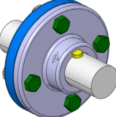
This section illustrates the developed approach through an example of parametric design problem of a flange coupling. A generic rigid flange coupling is shown in Figure 4.
The coupling is used to connect two shafts for power transmission. The functional requirements are to transmit the power between the connected shafts in a reliable and safe manner with the lowest possible loss of transmission as well as the optimum cost versus quality balance. The presented example provides a design method that integrates these requirements for a solution which remains consistent with the reliability, performance and safety requirements while being economical at the same time. The example is inspired from earlier research work on the selection of bolts for a coupling (Yvars et al., 2009).
Figure 4 Flange coupling model assembly (see online version for colours)
5.1 Problem description
A rigid flange coupling is to be designed for transmitting 39.5 kW of power from a four pole AC synchronous motor to a centrifugal pump. The shaft is made of steel alloy, flanges out of cast iron and bolts out of steel. The permissible stresses are given as: Shear stress on shaft (τs) = 100 MPa
Yield stress on shaft (σys) = 250 MPa Shearing stress on cast iron (τf ) = 200 MPa.
5.2 Design constraints
The following main relationships from the requirements are considered: The performance requirement is translated by the torque to be transmitted.
The safety and reliability requirement is translated by designing the coupling in a robust way to ensure the capacity of the coupling to transmit the torque while remaining within the zone of safe mechanical operations as given by the torque requirements and taking into account the uncertainty related to the design parameters.
Thedimensionaldesignofthecouplingshouldalloweaseofassemblyand disassembly using standard tools available with consideration to the studs/bolts being used.
5.3 Flange design
In order to establish the fundamental design model, it is considered that the material is homogeneous, isotropic and purely elastic. The holes drilled in the coupling are perfectly aligned and the coupling axes are concentric. The bolts used are assumed to have uniform mechanical properties. The elements are free of surface defects. Friction between surfaces follows the Coulomb law. All constraints are to be explored and no prior knowledge about the constraint effects exists. The design variables to be evaluated are presented in Figure 5 and are the key dimensional parameters of the flange as well as the selection of type and number of bolts.
Figure 5 Flange coupling sectional view
d D2 t D1 dn L DD D1
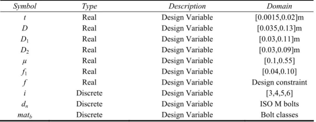
Table 1 shows the main design variables used in the example with their initial sets and types. Out of the 14 design parameters selected, seven are continuous variables whereas seven are discrete. The discrete variables may have additional defined attributes such as different material properties related to a specific bolt/flange material. Additional nomenclature related to the symbols used in the design model is presented in Appendix. Table 1 Variables for the coupling design example
Symbol Type Description Domain
t Real Design Variable [0.0015,0.02]m
D Real Design Variable [0.035,0.13]m
D1 Real Design Variable [0.03,0.11]m
D2 Real Design Variable [0.03,0.09]m
µ Real Design Variable [0.1,0.55]
f1 Real Design Variable [0.04,0.10]
f Real Design Variable Design constraint
i Discrete Design Variable [3,4,5,6]
dn Discrete Design Variable ISO M bolts
Table 1 Variables for the coupling design example (continued)
Symbol Type Description Domain
P Discrete Design Variable ISO M bolts
d2 Discrete Design Variable ISO M bolts
mb Discrete Design Variable ISO M bolts
pb Discrete Design Variable Tool Charts
t
∂ Real Noise Variable [–0.001,0.001]m
D
∂ Real Noise Variable [–0.001,0.001]m
1 D
∂ Real Noise Variable [–0.001,0.001]m
2 D
∂ Real Noise Variable [–0.001,0.001]m
μ
∂ Real Noise Variable ±2.5%
1 f
∂ Real Noise Variable ±2.5%
f
∂ Real Noise Variable ±2.5%
b
mat
∂ Real Noise Variable ±2.5%
In order to model the noise/uncertainty in the model, eight noise generating variables are defined related to the design variables. All other information related to the intermediate variables and references to the discrete variables has been taken from relevant ISO/US standards related to bolts and tools.
The basic analytical model of the coupling with the required constraints results into ten constraints which are described in the next section.
5.3.1 Mechanical constraints related to the flange torque transmission capacity
(
)
2 2 2 , hub f hub D T = =t πD τ T ≥T (10) , friction b m friction T =i F r Tμ ≥T (11) 2 4 4 2 16 , calculated calculated f f f T D T D d τ τ π ⎛ ⎞ = ⎜ ⎟ ≤ − ⎝ ⎠ (12)5.3.2 Mechanical constraints related to the bolt torque transmission capacity
2 1, 4 2 shear shear n b b b d D T =i⎛⎜π ⎞⎟τ T ≥T ⎝ ⎠ (13)
( )
1, 2 bbearing n b bbearing D T =i d t σ T ≥T (14) 3, m m i = i i≥ (15)( )
(
)
max max max 2 2 max 1 3 1 2 1 0 max 3 16 0.16 0.583 0.938194 0.9 min b b b ts b ts n b max t b s y eq C d C F p d f d d p F A F F eq σ σ τ τ π σ α σ σ = + = = + = − = = ≥ (16)5.3.3 Dimensional constraints ensuring the assembly and insertion of the bolts and their tightening
1 2 2 A C 2 b D ≥D + b + m (17) 1 2 A C 2 b D D≥ + b + m (18) 1 2 , c A C c b D s b s p i π = − ≥ (19) 5.4 Approach
Once the set of constraints, initial sets for the design parameters, and the noise variables have been defined, the design problem is evaluated for existence of a solution for a robust solution. The quantifiers are translated in computable form with interval mapping of each variable set to a corresponding interval and by transforming the constraints into the interval form using the principles described earlier.
In order to evaluate the robust solution consistency, uncertainty/variation sets are added to the corresponding design parameter in the constraint resulting in the interval-based robust design constraints. Using the application of equations (2) and (3) via their interval transformations, all the BSDs and hence the BD is evaluated. If a BSD does not fulfil any box consistency expression, it is excluded from search. However if the box consistency expression is validated for a solution, the BSD is regarded as having the possibility of solution and its evaluated for robust solution box consistency. If the latter expression is also validated then the space is regarded as a robust solution space; otherwise it is sub-divided and the process is repeated.
The coupling example, being a mixed problem containing continuous and discrete variables, needs a strategy for effective branching and bounding of the discrete and continuous design space. In this case, the continuous variables are branched first and then the discrete variables are evaluated for solution and robust solution consistency.
5.5 Results
The results obtained from the approach are divided into three types: the results of a pure parametric design of the coupling from a conventional point-based design, the results of a set-based design, and the results with noise variable integration.
The results obtained for the given example are shown in the form of three-dimensional projections between three variables D, D1 and D2. In Figure 6a and 6b, the
main box represents the initial BD projected in terms of the three selected variables with the starting intervals along their respective axes. In Figure 6a, green boxes after the first iteration show the possible search space (BSDs) marked by the algorithm for validated solution consistency. Figure 6b shows the sets of robust solution within the search space in the form of blue boxes after the first iteration for a robust solution. The choice of the discrete variables can also be shown in a similar way as shown in Figure 7.
Figure 6 Flange coupling example results (see online version for colours)
0.10 0.15 0.20 0.25 0.05 0.10 0.15 0.20 0.04 0.06 0.08 D 0.10 0.15 0.20 0.250.05 0.10 0.15 0.20 0.04 0.06 0.08 D2 D1 D D2 D1 (a) (b)
Figure 7 Flange coupling example-projection between real and discrete variables (see online
It is also possible to export the numerical tables for the results which can then be utilised for an analysis or representation of the results. Table 2 shows one of the robust solution sets found among other robust solution sets. These sets were verified by individual constraint verification which satisfied all the constraints.
Table 2 Set-based robust solutions for the coupling example
Variable Solution t [0.006125,0.01075]m D [0.21,0.25]m D1 [0.125,0.1625]m D2 [0.045,0.06]m µ [0.138,0.2755] f1 [0.12,0.1775] i 4 matb 2 dn 8 mm
The application of the developed method demonstrates the capacity of the approach to handle the problems containing a mix of discrete and continuous design variables. The possibility of a standard-based catalogue design selection procedure in the design problems for choosing from standardised alternatives was also shown. This validates the possibility of carrying out catalogue-based design by the developed approach. In conjunction with the discrete parameters, this example also shows the ability of the approach to handle the discrete and continuous variables together to satisfy the design constraints. This example also demonstrates a simultaneous approach towards dimensional as well as performance-based design of the system thereby ensuring that the final design rests on the robustness as well as operational capacity of the mechanism. 6 Discussion: reliability-based optimisation/robust design
optimisation/set-based robust design
The most commonly used methods to deal with uncertainty refer to reliability-based optimisation (RBDO). RBDO methods are based on the probability distributions to describe variability of design variables and model parameters. They intend to achieve systems with an acceptable level of reliability (failure probabilities) and a satisfying level of performance. A solution achieves reliability if the probability of satisfying each constraint is greater than a specified reliability level. RBDO methods consist of design optimisation with a reliability assessment.
While RDBO methods concern the probability of constraints satisfaction facing aleatory uncertainties, Robust Design Optimisation (RDO) aims at minimising the variations of the performance under epistemic uncertainty. There is still no clear definition of robustness, most of the authors agree to define that a robust solution is less sensitive to all sources of uncertainty. RDO methods intend to achieve systems with slight performance variations around their nominal values. The robust optimum solution is also reliable; in general, robustness does not imply reliability.
The proposed method (set-based robust design) as RDO is based on epistemic uncertainty to describe the variability of design variables and model parameters which is modelled by intervals. However, the aim of the proposed method is similar to RBDO: to find solutions with an acceptable level of reliability and a satisfactory level of performance.
To reduce the computing time of RBDO, set-based robust design can be used to reduce the research domain (design space).
7 Conclusion
The work presented in the paper proposes a new approach for a parallel exploration of design parameters as well as uncertainty and variation parameters for mechanical systems with the help of the set-based design and quantifier notion. Addressing the design parameters as sets permits a greater freedom of design choices and their evaluation.
The approach provides the capacity to treat the sets of the design parameters as well as the noise variables. This enables concurrent design space and variation space exploration. The resulting solutions that lie at the design space/variation space intersection are inherently robust and can accommodate the changes due to different variations such as manufacturing variations, small variations in the material properties as well as variations based on errors such as bolt preload force in the previous example and also the variations which may be induced into the design parameters due to any reason.
Each robust solution in the presented approach is a set of possibilities which performs according to the functional requirements. The approach also gives the designer a greater freedom over optimising the design solution with respect to a given constraint as the solution is presented over an envelope of different values of design parameters.
The quantifier notion used to express the requirements allows us to explicitly define the design requirements on the individual variables involved in a product design phase. The approach proposed in the paper allows the design engineer to integrate the notion of uncertainty in product design right from the early design phase and helps him to find the sensitive as well as the robust design regions in the possible product design search space. Different types of noise parameters can be treated by the proposed approach. In the treated example, the types of the uncertainties are of three types, i.e. dimensional uncertainties/variances, geometric uncertainties and material property uncertainties. From a mathematical point of view two different types of variables and uncertainties have been treated, i.e. discrete and continuous. The usage of interval analysis for conversion of the problem provides an appreciable gain in the computational time cost.
The presented application, however, also highlights one of the issues related to the handling of the problems with mixed discrete and continuous variables. With the increase in the number of discrete variables in conjunction with the continuous variables, the algorithm handling the branching and pruning of the design space faces a combinatorial explosion in the case of an exhaustive search algorithm and therefore risks increasing the time of the algorithm substantially.
In order to optimise the time and avoid combinatorial explosion, a discrete variable handling strategy in conjunction with the continuous domain pruning algorithm is required that may manage the decomposition of the BD in BSDs more efficiently in case of mixed problems.
References
Benhamou, F., Goualard, F., Granvilliers, L. and Puget, J.F. (1999) ‘Revising hull and box consistency’, International Conference on Logic Programming, pp.230–244.
Benhamou, F. and McAllester, D. (1994) ‘CLP (Intervals) revisited’, Proceedings of the 1994
International Symposium on Logic programming, Cambridge, MA, pp.1–16.
Benhamou, F. and Older, W.J. (1997) ‘Applying interval arithmetic to real, integer, and Boolean constraints’, The Journal of Logic Programming, Elsevier, Vol. 32, No. 1, pp.1–24.
Beyer, H. and Sendhoff, B. (2007) ‘Robust optimization – a comprehensive survey’, Computer
Methods in Applied Mechanics and Engineering, Vol. 196, Nos. 33/34, pp.3190–3218.
Bordeaux, L. and Monfroy, E. (2006) ‘Principles and practice of constraint programming – CP 2002’, Proceedings of 8th International Conference, CP 2002, Vol. 2470, Ithaca, NY, USA, pp.371–386.
Bordeaux, L., Monfroy, E. and Benhamou, F. (2003) ‘Towards automated reasoning on the properties of numerical constraints’, Recent Advances in Constraints, Springer, pp.407–420. Chang, T-S. and Ward, A.C. (1995) ‘Conceptual robustness in simultaneous engineering: a
formulation in continuous spaces’, Research in Engineering Design, Vol. 7, No. 2, pp.67–85. Chen, H. (2004) The Computational Complexity of Quantified Constraint Satisfaction, Cornell
University. Available online at: http://eccc.hpi-web.de/resources/pdf/mingchen.pdf
Chen, W., Allen, J.K., Tsui, K-L. and Mistree, F. (1996) ‘A procedure for robust design: minimizing variations caused by noise factors and control factors’, Journal of Mechanical
Design, Vol. 118, No. 4, pp.478–485.
Chenouard, R., Granvilliers, L. and Sebastian, P. (2009) ‘Search heuristics for constraint-aided embodiment design’, Artificial Intelligence for Engineering Design, Analysis and
Manufacturing, Vol. 23, No. 2, p.175.
Cruz, J. and Barahona, P. (2001) ‘Global hull consistency with local search for continuous constraint solving’, Progress in Artificial Intelligence, Springer, pp.77–83.
Cruz, J. and Barahona, P. (2003) ‘Maintaining global hull consistency with local search for continuous CSPs’, Global Optimization and Constraint Satisfaction, Springer, pp.178–193. Dantan, J-Y. and Ballu, A. (2002) ‘Assembly specification by Gauge with Internal Mobilities
(GIM) – a specification semantics deduced from tolerance synthesis’, Journal of
Manufacturing Systems, Vol. 21, No. 3, pp.218–235.
Dantan, J-Y., Mathieu, L., Ballu, A. and Martin, P. (2005) ‘Tolerance synthesis: quantifier notion and virtual boundary’, Computer-Aided Design, Vol. 37, No. 2, pp.231–240.
Dantan, J-Y. and Qureshi, A-J. (2009) ‘Worst-case and statistical tolerance analysis based on quantified constraint satisfaction problems and Monte Carlo simulation’, Computer-Aided
Design, Vol. 41, No. 1, pp.1–12.
East, D. and Truszczyński, M. (2006) ‘Predicate-calculus-based logics for modeling and solving search problems’, ACM Transactions on Computational Logic, Vol. 7, No. 1, pp.38–83. Eisenbart, B., Gericke, K. and Blessing, L.T.M. (2011) ‘A framework for comparing design
modelling approaches across disciplines’, Proceedings of the 18th International Conference
on Engineering Design (ICED11), Vol. 2, pp.344–355.
Finch, W.W. and Ward, A.C. (1997) ‘A set-based system for eliminating infeasible designs in engineering problems dominated by uncertainty’, Proceedings of ASME 1997 Design
Engineering Technical Conf Detc97/dtm-3886, Sacramento, California, pp.1–12.
Gent, I.P., Nightingale, P., Rowley, A. and Stergiou, K. (2008) ‘Solving quantified constraint satisfaction problems’, Artificial Intelligence, Vol. 172, Nos. 6–7, pp.738–771.
Gent, I.P., Nightingale, P. and Stergiou, K. (2005) ‘QCSP-Solve: a solver for quantified constraint satisfaction problems’, International Joint Conference on Artificial Intelligence (IJCAI 05), Morgan Kaufmann, pp.138–143.
Gericke, K. and Blessing, L.T.M. (2011) ‘Comparisons of design methodologies and process models across domains: a literature review’, Proceedings of the 18th International Conference
on Engineering Design (ICED11), Vol. 1, pp.393–404.
Gervet, C. (1997) ‘Interval propagation to reason about sets: definition and implementation of a practical language’, Constraints, Vol. 246, pp.191–246.
Lewis, K. and Mistree, F. (1998) ‘Collaborative, sequential, and isolated decisions in design’,
Journal of Mechanical Design, Vol. 120, pp.643–652.
Liker, J.K., Sobek, D.K., Ward, A.C. and Cristiano, J.J. (1996) ‘Involving suppliers in product development in the United States and Japan: evidence for set-based concurrent engineering’,
IEEE Transactions on Engineering Management, Vol. 43, No. 2, pp.165–178.
Malak Jr., R.J., Aughenbaugh, J.M. and Paredis, C.J.J. (2009) ‘Multi-attribute utility analysis in set-based conceptual design’, Computer-Aided Design, Elsevier Ltd, Vol. 41, No. 3, pp.214–227.
Mamoulis, N. and Stergiou, K. (2004) ‘Algorithms for quantified constraint satisfaction problems’,
Proceedings of CP-2004, pp.752–756.
McDowell, D., Panchal, J., Choi, H-J., Seepersad, C.C., Allen, J.K. and Mistree, F. (2010)
Integrated Design of Multiscale, Multifunctional Materials and Products, Design, Elsevier
Inc., p.392.
Mistree, F., Smith, W., Bras, B., Allen, J.K. and Muster, D. (1990) ‘Decision-based design: a contemporary paradigm for ship design’, Transactions on Society of Naval Architects and
Marine Engineers, Vol. 98, pp.565–597.
Nikolaidis, E., Ghiocel, D.M. and Singhal, S. (Eds) (2008) Engineering Design Reliability
Applications: for the Aerospace, Automotive and Ship Industries, CRC Press, p.376.
Parsons, S. (1992) ‘Contributed paper qualitative, semi-qualitative and interval algebras, and their application to engineering problems’, Engineering, Vol. 5, No. 6, pp.553–559.
Simpson, T.W., Rosen, D., Allen, J.K. and Farrokh, M. (1996) ‘Metrics for assessing design freedom and information certainty in the early stages of design’, ASME Design Engineering
Technical Conferences and Computers in Engineering Conference, pp.1–15.
Sobek II, D.K., Ward, A.C. and Liker, J.K. (1999) ‘Toyota’s principles of set-based concurrent engineering’, Sloan Management Review, Vol. 40, No. 2, pp.67–83.
Sébastian, P., Chenouard, R., Nadeau, J-P. and Fischer, X. (2007) ‘The embodiment design constraint satisfaction problem of the BOOTSTRAP facing interval analysis and genetic algorithm based decision support tools’, International Journal on Interactive Design and
Manufacturing (IJIDeM), Vol. 1, No. 2, pp.99–106.
Taguchi, G., Chowdhury, S. and Wu, Y. (2005) Taguchi’s Quality Engineering Handbook, John Wiley & Sons, p.1736.
Thornton, A.C. (1996) ‘The use of constraint-based design knowledge to improve the search for feasible designs’, Engineering Applications of Artificial Intelligence, Vol. 9, No. 4, pp.393–402.
Uebelhart, S.A. (2006) Non-Deterministic Design and Analysis of Parameterized Optical
Structures during Conceptual Design, Massachusetts Institute of Technology.
Vareilles, E. (2005) ‘Conception et approaches par propagation de constraints: contribution à la mise en œuvre d ’ un outil d ’ aide interactif’, L’institut National Polytechnique De Toulouse. Ward, A.C., Liker, J.K., Cristiano, J.J. and Sobek II, D.K. (1995) ‘The second toyota paradox: how
delaying decisions can make better cars faster’, Sloan Management Review, Vol. 36, No. 3, pp.43–61.
Yannou, B., Simpson, T.W. and Barton, R.R. (2003) ‘Towards a conceptual design explorer using metamodeling approaches and constraint programming’, Volume 2: 29th Design Automation
Yannou, B., Troussier, N., Chateauneuf, A., Boudaoud, N. and Scaravetti, D. (2009) ‘Dimensioning a product in preliminary design through different exploration techniques’,
International Journal of Product Development, Vol. 9, Nos. 1/2/3, p.140.
Yvars, P-A. (2008) ‘Using constraint satisfaction for designing mechanical systems’, International
Journal on Interactive Design and Manufacturing, Vol. 2, No. 3, pp.161–167.
Yvars, P-A. (2009) ‘A CSP approach for the network of product lifecycle constraints consistency in a collaborative design context’, Engineering Applications of Artificial Intelligence, Elsevier, Vol. 22, No. 6, pp.961–970.
Yvars, P.A., Lafon, P. and Zimmer, L. (2009) ‘Optimization of mechanical system: contribution of constraint satisfaction method’, International Conference on Computers & Industrial
Appendix
Description of abbreviations and symbols
Max. tensile stress in bolt
Coefficient of friction between flange surfaces Design shear stress in flange
Design shear stress in shaft Max. torsional stress in the bolt max max b s f s b σ μ τ τ τ = = = = = / 1 1
Tensile Stress Area
Bolt head length across corners Torsion moment in bolt due to preload Outside diameter of flange
nominal diameter of the shaft/ hub internal diameter Bolt circle diame
t A C A b C D d D = = = = = = 2 2 ter Hub outside diameter Pitch diameter of thread Bolt nominal diameter
n D d d = = = 1 0
Diameter of stress area
Friction coefficient between the bolt and the flange Minimum bolt tightening torque
Te min ts b d f F F = = =
= nsion load in each Bolt Number of bolts
Minimum bolt center distance from edge Pitch of thread
tool clearance Mean radius of surface
Proof Strength of bolt
Torque to Torque capacity ba
b b m p hub i m p p r S T T = = = = = =
= = sed on shear of flange at
the outside hub diameter
Torque transmission capacity due to friction Torque transmitted through bolts in shear
Torque capacity based on bearing of b shear bearing friction b b T T T = = = oltsbe transmitted Thickness of flange
Accuracy factor of tightening tool Bolt yield strength
Design stress in bolts Von Mise stress
s y b max t eq α σ σ σ = = = = =
![Figure 3 illustrates the algorithm with the help of a simple example. The BD is [–6,6]](https://thumb-eu.123doks.com/thumbv2/123doknet/7292703.208491/16.892.293.583.623.991/figure-illustrates-algorithm-help-simple-example-bd.webp)