Science Arts & Métiers (SAM)
is an open access repository that collects the work of Arts et Métiers Institute of
Technology researchers and makes it freely available over the web where possible.
This is an author-deposited version published in: https://sam.ensam.eu Handle ID: .http://hdl.handle.net/10985/18336
To cite this version :
Tiago JOSE DOS SANTOS MORAES, Mohamed TRABELSI, N.K. NGUYEN, Eric SEMAIL, Fabien MEINGUET - Inverter Fault Diagnosis of an Electrical Series-Connected Two Sinusoidal Six-Phase Permanent Magnet Machines Drive - Electric Power Applications p.1-9 - 2020
Any correspondence concerning this service should be sent to the repository Administrator : archiveouverte@ensam.eu
1
Inverter Fault Diagnosis of an Electrical Series-Connected Two Sinusoidal
Six-Phase Permanent Magnet Machines Drive
Tiago José dos Santos Moraes
1, Mohamed Trabelsi
1,
Ngac Ky Nguyen
1, Eric Semail
1, Fabien
Meinguet
21 Univ. Lille, Centrale Lille, Arts et MetiersInstitute of Technology , HEI, HESAM Université , EA 2697 - L2EP
- Laboratoire d’Electrotechnique et d’Electronique de Puissance, F-59000 Lille, France
2 Thales Alenia Space - Thales Group, Charleroi, Belgium
Abstract: This paper investigates a real-time fault diagnostic of a transportation system which needs two drives with fault-tolerance capabilities. Because of constraints on the mass of the system and on the cost of the Voltage Source Inverter (VSI), a drive with two Six-Phase Permanent Magnet Synchronous Machines (PMSM) in series-connection supplied by two six-leg inverters is chosen. Despite the serial -connection, independent control of the two machines and fault –tolerance to open-switch fault is ensured. Nevertheless, a Fault Detection Identification (FDI) process is required for analysis and/or control reconfiguration. The proposed FDI is based on the combination of different criteria obtained from the two zero-sequence currents and from the normalized currents mapped into two frames defined by the Concordia Transformation. Results obtained from simulation and experimental tests show the effectiveness of the proposal.
1. Introduction
In autonomous multi-machine transportation applications, the capability to ensure the system functionality with a minimum requirement in mass, volume and cost is appreciated. Fault-tolerant multiphase drives are a solution for these applications, because the fault of one power component does not lead to a breakdown. Multiphase machines have supplementary Degrees of Freedom (DoF) in comparison to regular three-phase machines, allowing the system to function in faulty mode. Consequently, oversizing the power components in order to warrant enough Mean Time Between Failure (MTBF) is then less necessary since a fault leads only to a decrease of the performances and not to a breakdown. Moreover, in normal mode the supplementary DoF can be addressed to energy management optimization. Several examples of energy optimization with multi-drive systems for automotive with several in-wheel motors are presented in [1]-[3] or dual-motor vehicles in [4]-[5]. For these applications, the speeds of the different machines are roughly the same, but the produced torque may differ. In the presented paper this kind of application is considered.
In [6], two different dual-motor drive topologies tolerant to short-circuit switch and open-phase faults are presented and compared. Two six-phase Permanent Magnet Synchronous Machines (PMSM) in open-end winding configuration supplied by H-Bridge are one of the solutions. However, constraints in mass, volume and cost make attractive another solution with series-connection of the two machines [6]-[7]. The number of transistors and of the DoF are of course decreased but it remains sufficient for fault mode operation with the occurrence of only one fault.
Multiphase drives with series connection have been widely studied at first, for induction machines [8]-[9], then for synchronous machines with sinusoidal electromotive forces [10] and non-sinusoidal electromotive forces [11]-[12]. Finally some studies have analysed their performance after an inverter fault [6]-[7], [13]-[14]. The independence of the control of each machine is ensured thanks to a special
coupling between the two machines, called "swapping connection" detailed in section II.
However, one main shortcoming of these systems is that the currents are crossing always all the series-connected machines: the efficiency is then decreased. Nevertheless, an economical interest exists for particular payloads: when the operation is predominantly intermittent or/and when the mass impacts the average energy consumption such as in aeronautic transportation. In these cases, the series-connection appears interesting since it reduces the investment cost.
Even if this system is fault tolerant, a Fault Detection Identification (FDI) is of interest. It could be useful in order to alert the user of the occurrence of a fault or to implement a specific fault control using the supplementary DoF of the system in order to improve its performance in faulty mode by reducing current amplitude or torque oscillation for example. Among the numerous existing FDI approaches presented in [15]-[23], the proposed FDI process belongs to a family based on the specificity of multiphase drives. For a n-phase machine, the phase currents can be projected in independent planes and axes. When the torque is only provided by currents’ projections on one plane (the one related to the fundamental harmonic of the currents for example), the projections of the currents on the other planes are thus equal to zero in normal operation mode. However, they quickly reach significant values after the occurrence of a fault. This sensitivity implies that the currents in the planes not associated to the torque production are reliable variables for FDI. Such FDI has been proposed for five-phase synchronous machines [18]-[20], and five and six-phase induction machines [21]-[22].
This paper investigates the adaptation of the FDI presented in [18] to series-connected machine drives. In [18], the FDI was proposed for a sinusoidal 5-phase PM machine. The currents projections in the x-y plane are negligible in normal operation and are used as variables for the FDI. In the present study of two 6-phase machines with the special series connection, both α-β and x-y current components are dedicated to torque generation. Consequently, the two zero-sequence current components which are weak in normal
2
mode and become quite significant in fault mode will beconsidered. As well, the symmetry of the 6-phase machines requests supplementary information for the fault localisation. The study presented in [23] has proposed a fault diagnostic for this family of drives. In [23], only the principle of FDI and simulation results have been provided. In the present paper, experimental results are also given in different conditions including transient operations in order to verify the robustness of the proposed method to torque and speed variation.
Section II presents the series-connected machines topology and its control. In section III, the post-fault operation is analysed in order to define the fault detection algorithm. Fault indexes for real-time application are depicted in Section IV. The last paragraph gives a presentation of experimental results and a robustness verification.
2. Series-Connected Two Six-Phase PMSM
Configuration and Control
Similar to the structure presented in [6] and [7], a connection scheme of the considered drive system is depicted in Fig. 1. There is a special electrical connection between the two machines that allows to control them independently. The two six-phase PMSM are symmetrical with a spatial shift between any two successive phase windings equal to 2π/6 (Fig. 2). This structure can result from different constraints [6]-[7]:
• Short-circuit and open-circuit transistor faults can be tolerated;
• Simple connection modification can transform a three-phase machine in a symmetrical six-phase machine;
• Only 24 transistors are necessary in comparison to 48, when two separately supplied open-end winding six-phase machines (H-bridge);
The main characteristics of the structure described in [6] and [7] are reminded before considering fault detection in the next section.
The phase currents of the two machines are interlinked as follows: [𝐼] = [𝐼𝑚1] = [ 1 0 0 0 −1 0 0 0 1 0 0 0 0 0 0 0 0 0 0 0 0 0 0 0 0 0 0 −1 0 0 0 1 0 0 0 −1] [𝐼𝑚2] (1)
To deduce a simple control scheme, the decomposition in fictitious machines concept has been successfully applied to the multiphase drives [24]. These fictitious machines are obtained by applying the linear Concordia transformation given in (2), resulting in the family of harmonic electrical components (voltage, current, back-EMF) illustrated in Table.1. Based on a such decomposition, it is possible to consider each six-phase PMSM as a set of two fictitious magnetically independent two-phase machines (main machine MM and secondary machine SM) and two fictitious zero-sequence one-phase machines (H1M and H2M). Each equivalent fictitious machine (respectively, MM, SM H1M and H2M) is associated to one decoupled plane or axis (respectively, α-β plane, x-y plane, h1 axis and h2 axis).
Table 1 Harmonic characterization of the fictitious machines
for six-phase open-end windings series-connected machines Fictitious machines Families of harmonics Main Machines (MM) 1, 5, 7, 11, ... 6k ± 1 Secondary Machines (SM) 2, 4, 8, 10, ... 6k ± 2 Zero-sequence machine 1 (H1M) 6, 12, ... 6k Zero-sequence machine 1 (H2M) 3, 9, ....6k±3
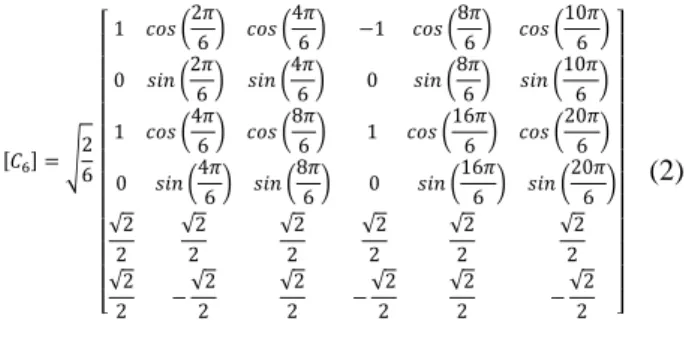
Considering the Concordia transformation presented as follows: [𝐶6] = √ 2 6 [ 1 𝑐𝑜𝑠 (2𝜋 6) 𝑐𝑜𝑠 ( 4𝜋 6) 0 𝑠𝑖𝑛 (2𝜋 6) 𝑠𝑖𝑛 ( 4𝜋 6) 1 𝑐𝑜𝑠 (4𝜋 6) 𝑐𝑜𝑠 ( 8𝜋 6) −1 𝑐𝑜𝑠 (8𝜋 6) 𝑐𝑜𝑠 ( 10𝜋 6 ) 0 𝑠𝑖𝑛 (8𝜋 6) 𝑠𝑖𝑛 ( 10𝜋 6 ) 1 𝑐𝑜𝑠 (16𝜋 6) 𝑐𝑜𝑠 ( 20𝜋 6 ) 0 𝑠𝑖𝑛 (4𝜋 6) 𝑠𝑖𝑛 ( 8𝜋 6) √2 2 √2 2 √2 2 √2 2 − √2 2 √2 2 0 𝑠𝑖𝑛 (16𝜋 6 ) 𝑠𝑖𝑛 ( 20𝜋 6 ) √2 2 √2 2 √2 2 −√2 2 √2 2 − √2 2 ] (2)
The relation between the currents of the fictitious machines is: [ 𝑖𝛼 𝑖𝛽 𝑖𝑥 𝑖𝑦 𝑖ℎ1 𝑖ℎ2] = [ 𝑖𝛼_𝑚1 𝑖𝛽_𝑚1 𝑖𝑥_𝑚1 𝑖𝑦_𝑚1 𝑖ℎ1_𝑚1 𝑖ℎ2_𝑚1] = [ 0 0 1 0 0 0 1 0 0 0 0 0 −1 0 0 0 0 0 0 −1 0 0 0 0 0 0 0 0 0 0 0 0 1 0 1 0 ][ 𝑖𝛼_𝑚2 𝑖𝛽_𝑚2 𝑖𝑥_𝑚2 𝑖𝑦_𝑚2 𝑖ℎ1_𝑚2 𝑖ℎ2_𝑚2] (3)
3
Fig. 2. Symmetrical six-phase 12-mwinding PMSM.Fig. 3. Control scheme.
Here, the main (α-β) machines are clearly decoupled from each other. Consequently, the current components of each main machine are independently controlled (Fig. 3), as addressed in [6]-[7]. From (3), the α-β currents generate the torque of M1’s main machine, as the x-y currents generate the torque of M2’s machine. The main machine of M1 is electrically coupled to the secondary machine of M2, and vice-versa. However, the currents driving the main machines flow through the secondary machines which generate no torque because these currents only interact with the even-harmonic back-EMF. These even even-harmonics are null for PMSM with symmetrical rotors considered in this paper.
3. Series-Connected PMSMs Post Fault Operation Analysis
This paper considers the occurrence of the most common inverter faults for a system inverter-machine: open-switch fault (OS) and open phase fault (OP). No consecutive faults are considered in this paper. By detecting those faults, it is possible to implement a reconfiguration in order to eliminate or attenuate the effect of the fault on the system performance. Among existing FDI presented in [15]-[17], the present FDI belongs to the family of signal based methods as reported in [19], [21], [25] and [26] which are distinguished with the model based methods as in [27]-[28]. More precisely the FDI is using the currents and not the voltages whose measured real values are difficult to use because the Voltage Source Inverter (VSI) are controlled by PWM. Nevertheless, it must be noted that, even if the model is not directly used in the algorithm, the physical knowledge of the drive and its control is necessary in order to define the criteria and the necessary
signal processing. In the present case, the choice of the zero-sequence currents for the detection and the other currents in the Concordia frames is based on a physical analysis.
Considering the problem of the FDI robustness to transient operation and for different working points, different normalized detection variables which are equal to zero in normal operation and tends to one in fault mode have been elaborated in case of three-phase drives [25]-[27] and also multiphase drives [19], [21] and [28] .
For multiphase drives, recent specific FDI have been proposed: they are since a few variables can be naturally equal to zero in normal operation and with high values in fault mode. These variables belong to subspace which are not contributing to the torque:
Signal equal to zero in normal operation: either by considering error between signal in fault and signal in normal operation [20], [28] or by considering a physical signal [18], [22] which is intrinsically equal to zero in normal operation multiphase
Similar to previous papers [18] and [23], the currents of the fictitious machines are analysed in degraded mode. Consequently, no extra sensor is needed. In Fig. 4, the currents in healthy and degraded mode after phase a is opened are presented. In degraded mode, the current of phase a is null due to the fault and the current of the other phases are unbalanced in amplitude and phase. In healthy mode the currents are slightly unbalanced too. This is due to the different load of each machine. Because of the electrical series-connection the current component for torque generation are combined unbalancing the phase currents even in healthy mode.
To overcome the problems related to the fast transients induced by the speed or torque changes, the currents used in this analysis are normalized. Then, equations (4), (5), (6)
Fig. 4. Motor phase current (up) and related zero-sequence
currents (down) obtained by simulation in normal mode and then with phase a open.
4
present the proposed normalization. This normalizationconsiders that the two di-phase fictitious machines are decoupled in healthy mode and that their currents are related to the torque of each machine. Consequently; the α-β and x-y currents are unitary amplitude sinusoidal curves in healthy mode, independently of the torque generated by each real machine. On the other hand, the zero-sequence currents are normalized by all current components.
[𝑖ℎ1ℎ2𝑁] = [𝑖ℎ1ℎ2] (𝑖𝛼2+ 𝑖𝛽2+ 𝑖𝑥2+ 𝑖𝑦2+ 𝑖ℎ12 + 𝑖ℎ22 ) 1 2 (4) [𝑖𝛼𝛽𝑁] = [𝑖𝛼𝛽] (𝑖𝛼2+ 𝑖𝛽2+ 𝑖ℎ12 + 𝑖ℎ22 ) 1 2 (5) [𝑖𝑥𝑦𝑁] = [𝑖𝑥𝑦] (𝑖𝑥2+ 𝑖𝑦2+ 𝑖ℎ12 + 𝑖ℎ22 ) 1 2 (6)
The zero-sequence current components are not used for the torque production and are almost null under a healthy operation mode (ih1 ≈ ih2 ≈ 0), resulting in no effect on the
normalized quantities in (4)-(6) .These components have a particular evolution after the occurrence of an opened-switch or opened-phase fault in the VSI (Fig. 4).
Simulation results of the inverter fault effects analysis in
α-β, x-y and h1-h2 frames are shown in Fig. 5 for two
open-switch faults and an open-phase fault, all for the same phase (phase A). For a healthy condition, the phase currents contain only fundamental harmonic components. As a result, the shapes built in α-β and x-y frames are two circles centred at the origin, and ideally only a point at the origin in the h1-h2 frame.
In post-fault operation mode, the shapes are no longer circular, and the fault induces different trajectories in both α-β and x-y frames. Their relative position and shape are linked directly to the faulty switch location. In h1-h2 frame, for an open-switch or an open-phase fault, bidirectional components with high relative values in comparison with those existing in healthy condition are appearing. Adding this characteristic to the information derived from the particular behaviour of the current shapes in α-β and x-y frames leads to a FDI process designing, as addressed in the next section.
Based on simulation results, Table. 2 and
Fig. 6, summarize the different directions of the average positions in α-β, x-y and h1-h2 planes. Tk and Tk+6 denote,
respectively, the upper and the lower transistors of the first VSI (left side in Fig. 1). T'k and T'k+6 denote, respectively, the
upper and the lower transistors of the second VSI (right side in Fig. 1). As the electric drive system is composed by symmetric even-phase machines, there are two phases sharing the same direction axis in α-β and x-y planes (e.g., phase a and phase d). But thanks to the coupling between the machines, the phases b, d and f (the even phases and their switches) have a different behaviour when comparing between the α-β and x-y frames. This difference shows that even if one frame is not enough to localize the faulty switch, each one of them has its own shape average position when combining both frames.
For both OS or OP faults, it is interesting to distinguish two families of phase current: (𝑖𝑎, 𝑖𝑐, 𝑖𝑒) and (𝑖𝑏, 𝑖𝑑, 𝑖𝑓) which will be respectively called odd and even currents in the rest
of the paper. Simulation results shown in Fig. 4 provide the dynamic behaviour of the six-phase currents for a healthy VSI
Fig. 5. Simulation results for the current trajectories in
Concordia frames (α-β, x-y, h1-h2) under open-switch (a) or open-phase fault (b) in phase a.
and in post-fault operation mode. The considered fault is the phase-a opened. The rotor speeds of the two machines are fixed to 𝜔1= 𝜔2= 50𝑟𝑎𝑑/𝑠. The load torques, T1 = 4 Nm and T2 = 2 Nm, are applied to machine 1 (M1) and machine 2 (M2), respectively.
After the open-phase fault occurrence, considering the closed-loop vector control of PMSMs, speed and current controllers are not able to achieve zero errors in post-fault operation mode resulting in unbalanced faulty system. The faulty phase current 𝑖𝑎 is now null. Regarding the other healthy phase currents, their shapes are changed and remain flowing in negative and positive directions.
Table 2 Normalized phase currents average positions in
Concordia frames (α-β, x-y, h1-h2) for a healthy and faulty VSIs.
Fault
location k =1,..,6
Current shape average position in Concordia frames α-β frame x-y frame h1-h2 frame Healthy VSIs 0 0 0 Tk or T'k+6 Odd (2k+3)π/6 (2k+3)π/6 ≠0 Even (2k-3)π/6 ≠0 Tk+6 or T'k Odd (2k-3)π/6 (2k-3)π/6 ≠0 Even (2k+3)π/6 ≠0 Tk & Tk+6 or 0 0 ≠0 (a) (b)
5
T'k & T'k+6 iβN (t) iαN (t) Healthy VSI 2π/6 2π/6 2π/6 2π/6 2π/6 2π/6 T6 T9 T5 T8 T4 T7 T3 T12 T2 T11 T1 T10 iyN (t) ixN (t) Health y VSI 2π/6 2π/6 2π/6 2π/6 2π/6 2π/6 T9 T12 T2 T5 T7 T10 T3 T6 T8 T11 T1 T4 ih2N (t) ih1N (t) Healthy VSI Faulty VSIFig. 6. Current shapes average position in Concordia frames
according to the faulty switch location.
The harmonic contents of the phase currents in the healthy condition and under open-phase fault are depicted in Fig. 7a and Fig. 7b for the odd and even phase currents, respectively. Because of the electrical coupling of the motors, the three odd phases have a particular behaviour in comparison to the even ones. In pre-fault operation mode, the harmonic content of each phase current is well known and contains only the fundamental component, as explained in section 2.2. On the contrary, the fault occurrence in the phase-a, results only in modification of the magnitude of the fundamental components of the odd phase currents (𝑖𝑐, 𝑖𝑒) without introducing others harmonic components.
Regarding the three even-phase currents (𝑖𝑏, 𝑖𝑑, 𝑖𝑓), their harmonic content is similar to the one obtained in pre-fault operation mode. This means that the open-phase fault of an odd (respectively even) motor winding implies only a modification of the magnitudes of the odd (respectively even) phase currents.
4. Real-Time Inverter Fault diagnostic method
In this section, the real-time inverter fault diagnostic technique is described. The block diagram of the proposed algorithm is depicted in Fig. 8. This algorithm permits detecting the fault occurrence in the VSI and identifying the faulty switches as well as the faulty phases.
The measured signals used by the FDI method are only the phase currents (𝑖𝑎, 𝑖𝑏, 𝑖𝑐, 𝑖𝑑, 𝑖𝑒 and 𝑖𝑓) and the rotor speeds (ω1 and ω2).
Firstly, fault detection step is achieved by monitoring the fault current components in h1-h2 frame. It is computed using the variable 𝐹𝑑𝑁(𝑡) as follows:
𝐹𝑑𝑁(𝑡) = 〈√𝑖ℎ1𝑁2 (𝑡) + 𝑖ℎ2𝑁2 (𝑡)〉 (7) As zero-sequence currents are controlled to be null, 𝐹𝑑𝑁(𝑡) is almost zero. On the contrary, if an open-switch or an open-phase fault occurs in the VSI, the variable 𝐹𝑑𝑁(𝑡) becomes positive and exceeds a fixed threshold THd.
Unfortunately, the detection variable 𝐹𝑑𝑁(𝑡) is sensitive to both open-switch and open-phase fault. Therefore, second
variables 𝐹𝑖−𝛼𝛽𝑁(𝑡) and 𝐹𝑖−𝑥𝑦𝑁(𝑡) are necessary to identify the faulty open-switch in the VSI. This step uses the average
Fig. 7. Experimental results: harmonic contents of the phase
currents for a normal operation mode and under an open-phase fault (motor open-phase a opened). (a) Odd open-phase currents a, c, e. (b) Even phase currents b, d, f.
position of the computed current trajectories using the mean values of the current components in α-β and x-y frames as follows • in α-β frame 𝐹𝑖−𝛼𝛽𝑁(𝑡) = 𝑎𝑡𝑎𝑛 ( 〈𝑖𝛽𝑁(𝑡)〉 〈𝑖𝛼𝑁(𝑡)〉 + 𝜀) = {(2𝑘 + 4) 𝜋 6, if (𝑇𝑘 𝑜𝑟 𝑇𝑘+6′ ) is faulty (2𝑘 − 2)𝜋 6, if (𝑇𝑘′ 𝑜𝑟 𝑇𝑘+6) is faulty (8) • in x-y frame 𝐹𝑖−𝑥𝑦𝑁(𝑡) = 𝑎𝑡𝑎𝑛 ( 〈𝑖𝑦𝑁(𝑡)〉 〈𝑖𝑥𝑁(𝑡)〉 + 𝜀) = { (2𝑘 + 4)𝜋6, 𝑘 odd (2𝑘 − 2)𝜋 6, 𝑘 even , if (𝑇𝑘 𝑜𝑟 𝑇𝑘+6′ ) is faulty (2𝑘 − 2)𝜋 6, 𝑘 odd (2𝑘 + 4)𝜋 6, 𝑘 even , if (𝑇𝑘′ 𝑜𝑟 𝑇𝑘+6) is faulty (9)
is a weak constant value allowing the identification variables equal to zero in pre-fault operation mode and it has no effect on the identification variables in post-fault operation mode. The mean values of the current components in the orthogonal planes are computed as follows:〈𝑥𝑖(𝑡)〉 = 1 𝑇𝑖(𝑡)∫ 𝑥𝑖𝑑𝑡 𝑇𝑖(𝑡) 𝑡−𝑇𝑖(𝑡) (10)
6
xi(t) denotes current component iαN, iβN, ixN and iyN. A dynamic
sliding window [𝑡 − 𝑇𝑖; 𝑇𝑖] is used to improve the immunity of the algorithm against false alarms since it acts as a low-pass filter, in which 𝑇𝑖 is the electric period of the machine.
Considering the analysis given in Section 3, it has been addressed that an open-switch fault results in a half-plane shape in α-β and x-y frames. Therefore, using (8) and (9), the FDI process calculates the fault shape average position in these frames. For the system under study, there are six distinct average positions in each orthogonal frame according to the involved faulty switch, as addressed in Fig. 6.
The 𝐹𝑖−𝛼𝛽𝑁(𝑡) and 𝐹𝑖−𝑥𝑦𝑁(𝑡) diagnostic variables carry information about the faulty switches only. For a complete diagnostic procedure, the proposed FDI process is extended to the open-phase fault detection and localization. An index is then calculated for each phase, in which the RMS value of each current is calculated. This index is normalized by a half of the RMS of the other currents of the same family (even or odd phases). 𝐹𝑛𝑁(𝑡) = 2√〈𝑖𝑛𝑁2 (𝑡)〉 √〈𝑖𝑙𝑁2 (𝑡)〉 + √〈𝑖 𝑚𝑁2 (𝑡)〉 (11)
where l, m, n {1, 3, 5} for odd motor phase, and l, m, n {2, 4, 6} for even motor phases with always l ≠ m ≠ n. The variables Fn _ N( t ) are close to 1 for a healthy electric drive system. On the contrary, when an open-phase fault occurs in the VSI, the corresponding diagnostic variable drops to zero and becomes less than a fixed threshold 𝑇𝐻𝑜𝑝. Table 3 summarizes the states of the output signals of the FDI process according to the faulty switch or the faulty phase.
The period T of the sliding window used to calculate all the fault detection indexes is equivalent to one electrical period. Consequently, the speed of the machine is related to the fault detection duration. If the purpose of the fault detection is to implement a fault control, it takes at least one electrical period to accurately detect and locate the fault. When the speed of the machines is null, the period T tends to infinity. Hence the value of T is limited to a period equivalent to a speed of 5rad/s.
For the application proposed in this paper, the in-wheel motor speeds are most of the time the same. For the other indexes, the signal present harmonics related to the speed of each machine. That is why this method can be applied to system in which the machine’s speeds are the same or close. When the speeds are slightly different, the mean value of both speeds is used in order to minimize the error. There are three threshold values used by the proposed diagnostic algorithm in this work.
The threshold THd is used to detect the fault occurrence in the
VSI. Based on the explanation given in section 3, THd is
selected equal to 0.1, permitting thus a large dissymmetry between the values that can be taken by the detection variable 𝐹𝑑𝑁(𝑡) under healthy conditions and when an open-switch or an open-phase fault occurs in the VSI. With similar reasoning, the threshold value 𝑇𝐻𝑜𝑝 used to judge the open-phase fault occurrence is fixed to 0.1. Finally, the third threshold PTh is used to decide on the position of the identification variables 𝐹𝑖−𝛼𝛽𝑁(𝑡) and 𝐹𝑖−𝑥𝑦𝑁(𝑡) in α-β and x-y frames. As these variables are with one of the defined directions in Fig. 6 according to the faulty switch, a security margin of PTh = ±25° is fixed, allowing a large dissymmetry between each two successive positions.
Fig. 8. Block diagram of the proposed diagnostic algorithm.
Table 3 FDI process output-signal states for a healthy VSI and under open-switch and open-phase fault modes
Fault location
k =1,..,6
FDI process output-signals
𝐹𝑑𝑁(𝑡) 𝐹𝑖−𝛼𝛽𝑁(𝑡) 𝐹𝑖−𝑥𝑦𝑁(𝑡) 𝐹𝑎,𝑐,𝑒_𝑁(𝑡) 𝐹𝑏,𝑑,𝑓_𝑁(𝑡)
Healthy VSIs 0 0 0 ≅ 1 > THop ≅ 1 > THop
Open-switch fault Tk or T'k+6 odd > THd (2k+3)π/6 (2k+3)π/6 > THop > THop even > THd (2k-3)π/6 Tk+6 or T'k odd > THd (2k-3)π/6 (2k-3)π/6 even > THd (2k+3)π/6
7
Open-phase fault Tk & Tk+6 or T'k & T'k+6 > THd 0 0 < THop < THopBeyond this, the selected threshold values are then verified by simulation and by running several experiments under healthy and faulty operation conditions, resulting in a high immunity to false alarms.
5. Performance Evaluation Results and comments
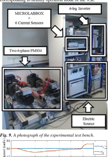
To check the performance and the effectiveness of the proposed FDI process, several simulation and experimental tests are performed on a prototype as addressed in Section. 2. In accordance with Fig. 1, it is composed of series-connected two identical six-phase PMSM supplied by two six-leg VSIs and a dc-bus voltage. Each machine is coupled to an industrial motion drive which is used as an emulator to generate different load profiles. The special series-connection of the two machines ensure that the inductances Lαβ of one machine are in series with the inductances Lxy of the second machine. A photograph of the experimental test bench is depicted in Fig. 9.
The parameters of each PMSM are given in Table 4. Rs is the stator resistance. Lαβ, Lxy, Lh1 and Lh2 are respectively the inductances of the fictitious machines (MM, SM, H1M and H2M). The proposed diagnostic algorithm as well as the vector control algorithm are tested in simulation and then implemented in a dSPACE Micro-Lab-Box controller board with an execution sampling frequency of 10-kHz. The PWM-VSI is running with a switching frequency of 10-kHz.
Simulated and experimental tests investigate FDI process robustness and effectiveness for a healthy operation mode and when an open-circuit fault occurs in the VSI. The discussion and comments on the obtained results are addressed below. In a first step, for a healthy operation mode, different tests have been carried out to evaluate the robustness and the immunity of the proposal to false alarms especially during fast transients as speed or load torque changes. Then, two fault modes are investigated; an open-switch fault and an open-phase fault in the VSI.
Table 4 Electrical Parameters of each 6-Φ PMSM
Rs Lαβ Lxy Lh1=Lh2 p Vdc 0.77 Ω 0.01 H 0.011 µH 0.008 µH 4 200V Max. power Max. Current Rate voltage Rate Speed Max Speed 15kW 11.8A 485V 3500 rpm 12000 rpm
5.1. Immunity of the diagnostic algorithm to transient states
Fig. 10 shows the time-domain waveforms of the currents in rotating frames (image of the torque), the speeds and the diagnostic variables for a healthy operation mode of the drive system. In this test, the two series-connected M1 and M2 run at constant speed equal to 𝜔 = 50 rad/s . It is for example the case of two wheels, of an automotive in a straight line without slipping. The experimental investigation is achieved as following. Fast transients are obtained by unloading/loading each machine alone, while the initial reference speeds are maintained constants. Regarding the diagnostic algorithm robustness, the obtained results show that loading/unloading of these machines has no consequence
on the robustness and the immunity of the FDI process, since the diagnostic variable 𝐹𝑑𝑁 remains always in the region corresponding to healthy operation mode of the VSI.
Fig. 9. A photograph of the experimental test bench.
Fig. 10. Experimental results of the diagnostic algorithm
8
Fig. 11. Experimental results of the diagnostic algorithmimmunity to false alarms. Time-domain waveforms of the phase currents, the rotor speeds of the two series-connected machines and the diagnostic variables during speed change.
In the second test, a speed profile between 10 and 50 rad/s is imposed to the system, while the torque references are fixed to 2 Nm and 4 Nm, respectively. The obtained results are depicted in Fig. 11. Regarding the diagnostic variables, even though light deformation of 𝐹𝑑𝑁 is observed, it is always within the band that corresponds to the healthy operation mode of the VSI. Once more, the obtained results confirm the high performance of the proposed FDI process under speed change.
5.2. Diagnostic algorithm effectiveness
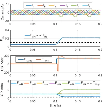
The experimental results reported in Fig. 12 to Fig. 14 address the FDI process effectiveness under an open-switch fault. The two six-phase machines are loaded to 2 Nm and 4 Nm and run at the rotor speed equal to 50 rad/s. The Iq components pictured in Fig. 12 are an image of the torque of each machine. The zero-sequence current components are depicted in Fig. 13. As concluded in the theoretical part, these components are null under a healthy VSI and increase significantly for a faulty one. Considering Fig. 14, it illustrates the time-domain waveforms of the line currents, the variable FdN (t), the variables 𝐹𝑖−𝛼𝛽𝑁(𝑡) and 𝐹𝑖−𝑥𝑦𝑁(𝑡), and the variables Fn_N (t). The open-switch fault is applied to
the upper transistor T1 at t = 0,1 s, by keeping its switching signal permanently in "Off" state. As a result, the phase current 𝑖d suddenly reaches to zero and is limited to flow only in the negative direction, while other currents undergo a light deformation and remains flowing in negative and positive directions. Regarding the detection variable FdN (t), it
increases immediately and exceeds the threshold Th at
t=0,106 s, indicating thus the fault occurrence in the VSI. The
average positions of the phase currents in α-β and x-y frames are indicated by the variables 𝐹𝑖−𝛼𝛽𝑁(𝑡) and 𝐹𝑖−𝑥𝑦𝑁(𝑡). Here, it is observed that they converge quickly to values close to 150°. These average positions correspond effectively to the fault occurrence in transistor T1. The variable Fn-N (t) are
always within the band corresponding to no open-phase fault in the VSI.
The time-domain waveforms of the phase currents, the diagnostic variables and zero-sequence currents are reported in Fig. 13 and Fig. 14. When the fault occurs, the variable FdN
(t) exceeds the threshold Th, permitting a fault detection at t = 1.07 s. For the identification of the fault (open-circuit of
phase a), it is necessary to wait at t=1.115s that the variable
Fa-N (t) crosses the threshold THop., identifying the fault as
open-circuit of phase a.
6. Conclusion
This work addresses a signal-based FDI process for inverter open-switch and open-phase fault real-time diagnosis in a drive composed of two electrical series-connected six-phase PMSM supplied by two VSIs. There is no extra hardware or extra sensors required by the proposal since the algorithm uses only the available current sensors which are already used for closed-loop control of the machines.
The algorithm is based on the particular characteristics offered by the fictitious multi-machine representation in the subspaces h1-h2, α-β and x-y. As both α-β and x-y current
components contribute to torque generation, the fictitious h1 -h2 plane was the one used for the fault-detection. As well, the
symmetry of the 6-phase machines obliged also the use of both α-β and x-y planes in order to localise the faulty switch.
Fig. 12. Experimental results. Time-domain waveforms of the
Iq components during healthy and faulty operation mode.
Fig. 13. Experimental results. Time-domain waveforms of the
zero-sequence current components during healthy and faulty operation mode.
9
Fig. 14. Experimental results of the diagnostic algorithmeffectiveness. Time-domain waveforms of the phase currents and the diagnostic variables when an open-circuit fault occurs in transistor T1.
An adequate normalization procedure is used to make the FDI process robust against transient states due to speed and torque change.
Simulation and experimental results achieved on a prototype prove the effectiveness and robustness of the proposed method. However, at very low or zero torque and speed regions, the proposed method should be improved. This point will be taken in a future work.
7. Acknowledgments
This work has been achieved within the framework of CE2I project. CE2I is co-financed by European Union with the financial support of European Regional Development Fund (ERDF), FrenchState and the French Region of Hauts-de-France
8. References
[1] Y. Wang, H. Fujimoto and S. Hara, "Driving Force Distribution and Control for EV With Four In-Wheel Motors: A Case Study of Acceleration on Split-Friction Surfaces," IEEE Transactions on Industrial Electronics, vol. 64, no. 4, pp. 3380-3388, April 2017.
[2] D. Zhang, G. Liu, H. Zhou and W. Zhao, "Adaptive Sliding Mode Fault-Tolerant Coordination Control for Four-Wheel Independently Driven Electric Vehicles," in IEEE Transactions on Industrial Electronics, vol. 65, no. 11, pp. 9090-9100, Nov. 2018.
[3] H. Zhou, Z. Liu, and X. Yang, “Motor Torque Fault Diagnosis for Four Wheel Independent Motor-Drive Vehicle Based on Unscented Kalman Filter,” IEEE
Transactions on Vehicular Technology, vol. 67, no. 3,
pp. 1969–1976, Mar. 2018.
[4] X. Hu, Y. Li, C. Lv, and Y. Liu, “Optimal Energy Management and Sizing of a Dual Motor-Driven Electric
Powertrain,” IEEE Transactions on Power Electronics, pp. 1–1, 2018.
[5] W. Wang, Z. Zhang, J. Shi, C. Lin, and Y. Gao, “Optimization of a Dual-Motor Coupled Powertrain Energy Management Strategy for a Battery Electric Bus Based on Dynamic Programming Method,” IEEE
Access, vol. 6, pp. 32899–32909, 2018.
[6] T.J. Dos Santos Moraes, N. K. Nguyen, E. Semail, F. Meinguet and M. Guerin, "Dual-Multiphase Motor Drives for Fault-Tolerant Applications: Power Electronic Structures and Control Strategies," in IEEE Transactions on Power Electronics, vol. 33, no. 1, pp. 572-580, Jan. 2018
[7] T. J. Dos Santos Moraes, N. K. Nguyen, F. Meinguet and E. Semail, "Fault tolerant dual-motor drives: Sizing of power electronic," 2015 17th European Conference on Power Electronics and Applications (EPE'15 ECCE-Europe), Geneva, 2015, pp. 1-10.
[8] S. Gataric, "A polyphase cartesian vector approach to control of polyphase AC machines," IAS Conference on Industrial Applications of Electrical Energy, Rome, 2000, pp. 1648-1654 vol.3.
[9] E. Levi, S. N. Vukosavic and M. Jones, "Vector control schemes for series-connected six-phase two-motor drive systems,"IEE Proceedings-Electric Power Applications, vol. 152, no. 2, pp. 226-238, 4 March 2005.
[10] E. Levi, M. Jones and S. N. Vukosavic, "A series-connected two-motor six-phase drive with induction and permanent magnet machines," Trans. on Energy Conversion, vol. 21, no. 1, pp. 121-129, March 2006. [11] E. Semail, E. Levi, A. Bouscayrol, X. Kestelyn,
"Multi-machine modelling of two series connected 5 phase synchronous machines: effect of harmonics on control", Proc. Eur. Conf. Power Electron. Appl., pp. 1-10, Sep. 2005
[12] F. Mekri, J-F Charpentier, E. Semail, “An efficient control of a series connected two-synchronous motor phase with non sinusoidal EMF supplied by a single 5-leg VSI: Experimental and theoretical investigations”, Electric Power Systems Research, Volume 92, Nov. 2012, Pages 11-19
[13] W. Wang, M. Cheng, B. Zhang, Y. Zhu, and S. Ding, “A Fault-Tolerant Permanent-Magnet Traction Module for Subway Applications,” IEEE Trans. Power Electron., vol. 29, no. 4, pp. 1646–1658, Apr. 2014.
[14] Y. Zhou and G. Chen, “Predictive DTC Strategy With Fault-Tolerant Function for Six-Phase and Three-Phase PMSM Series-Connected Drive System,” IEEE Transactions on Industrial Electronics, vol. 65, no. 11, pp. 9101–9112, Nov. 2018.
[15] H. Henao et al., "Trends in fault diagnosis for electrical machines: A review of diagnostic techniques", IEEE Ind. Electron Mag., vol. 8, no. 2, pp. 31-42, Jun. 2014. [16] M. Riera-Guasp, J. A. Antonino-Daviu, G. A. Capolino,
"Advances in electrical machine power electronic and drive condition monitoring and fault detection: State of the art", IEEE Trans. Indus. Electron., vol. 62, no. 3, pp. 1746-1759, Mar. 2015
[17] Z. Gao, C. Cecati, S. X. Ding, “A survey of fault diagnosis and fault-tolerant techniques—Part 1: fault Diagnosis with model-based and signal-based approaches,ˮ IEEE Trans. Indus. Electron., vol. 62, no. 6, pp. 3757-3767, Jun. 2015.
10
[18] M. Trabelsi, N. K. Nguyen, E. Semail, “Real-timeSwitches fault diagnosis based on typical operating characteristics of five-phase permanent magnetic synchronous machines,” IEEE Trans. Indus. Electron.,., vol. 63, no. 8, pp. 4683-4694, Aug. 2016
[19] AKM Arafat, Seungdeog Choi, Jeihoon Baek, "Open-Phase Fault Detection of a Five-"Open-Phase Permanent Magnet Assisted Synchronous Reluctance Motor Based on Symmetrical Components Theory", IEEE Trans. Indus. Electron., vol. 64, no. 8, pp. 6465-6474, 2017. [20] M. Trabelsi, E. Semail, and N. K. Nguyen,
“Experimental Investigation of Inverter Open-Circuit Fault Diagnosis for Biharmonic Five-Phase Permanent Magnet Drive,” IEEE Journal of Emerging and Selected
Topics in Power Electronics, vol. 6, no. 1, pp. 339–351,
Mar. 2018.
[21] I. González-Prieto, M. J. Duran, N. Rios-Garcia, F. Barrero, C. Martín, "Open-Switch Fault Detection in Five-Phase Induction Motor Drives Using Model Predictive Control", IEEE Trans. Indus. Electron.,, vol. 65, no. 4, pp. 3045-3055, 2018.
[22] M. J. Duran, I. Gonzalez-Prieto, N. Rios-Garcia and F. Barrero, "A Simple, Fast, and Robust Open-Phase Fault Detection Technique for Six-Phase Induction Motor Drives," IEEE Trans. on Power Electron., vol. 33, no. 1, pp. 547-557, Jan. 2018.
[23] T. J. Dos Santos Moraes, M. Trabelsi, N. K. Nguyen, E. Semail, F. Meinguet and M. Guerin, "Inverter open circuit faults diagnosis in series-connected six-phases permanent magnet drive," International Symposium on Diagnostics for Electrical Machines, Power Electronics and Drives (SDEMPED), Tinos, 2017, pp. 188-194 [24] X. Kestelyn, E. Semail, “A vectorial approach for
generation of optimal current references for multiphase permanent-magnet synchronous machines in real time,ˮ IEEE Trans. Indus. Electron., vol. 58, no. 11, pp. 5057-5065, Nov. 2011.
[25] W. Sleszynski, J.Nieznanski, A. Cichowski, "Open-transistor fault diagnostics in voltage-source inverters by analyzing the load currents," IEEE Trans. Indus. Electron., vol.56, no.11, pp.4681-4688, 2009.
[26] J. O. Estima, A. J. Marques Cardoso, “A new algorithm for real-time multiple open-circuit fault diagnosis in voltage-fed PWM motor drives by the reference currents errors,ˮ IEEE Trans. Indus. Electron., vol. 28, no. 5, pp. 3496-3505, Aug. 2013.
[27] D. U. Campos-Degado, D. R. Espinoza-Trejo, "An observer-based diagnosis scheme for single and simultaneous open-switch faults in induction motor drives," IEEE Trans. Indus. Electron.,vol.58, no.2, pp. 671-679, 2011.
[28] M. Salehifar, R. S. Arashloo, J. M. Moreno-Equilaz, V. Sala, L. Romeral, “Fault detection and fault tolerant operation of a five phase PM motor drive using adaptive model identification approach,ˮ IEEE J. Emerging Sel. Top. Power Electron, vol. 2, no. 2, pp. 212-223, Jun. 2014.