OATAO is an open access repository that collects the work of Toulouse researchers and makes it freely available over the web where possible
Any correspondence concerning this service should be sent
to the repository administrator: [email protected]
This is an author’s version published in: http://oatao.univ-toulouse.fr/27633
To cite this version:
Ropars, Ludovic and Dehmas, Moukrane and Aeby-Gautier, Elisabeth and Tricker, David and Schuster, Dominique and Gourdet, Sophie Effect of Processing Route on Microstructure and Mechanical Properties of a Ti-3Al-2.5V/TiB
Composite. (2018) Materials Science Forum, 941. 1950-1955. ISSN 1662-9752 Official URL: https://doi.org/10.4028/www.scientific.net/MSF.941.1950
Effect of Processing Route on Microstructure and Mechanical
Properties of a Ti-3Al-2.5V/TiB Composite
Ludovic Ropars
1,2,a*, Moukrane Dehmas
3,b, Elisabeth Aeby-Gautier
2,c,
David Tricker
4,d, Dominique Schuster
5,e, Sophie Gourdet
1,f1Airbus Group SAS, Airbus Group Innovations, 12 rue Pasteur, 92150 Suresnes, France. Now at
Ariane Group, 51-61 route de Verneuil, 78130 Les Mureaux, France.
2Institut Jean Lamour, UMR 7198, CNRS Université de Lorraine, Campus ARTEM, 2 allée André
Guinier, BP 50840, 54011 Nancy Cedex, France.
3Institut Jean Lamour, UMR 7198, CNRS Université de Lorraine, Campus ARTEM, 2 allée André
Guinier, BP 50840, 54011 Nancy Cedex, France. Now at CIRIMAT, Université de Toulouse, CNRS, INPT, UPS, 4 allée Emile Monso, 31030 Toulouse, France.
4Materion AMC, 1 RAE Road, Farnborough, Hampshire, GU14 6XE, United Kingdom. 5Airbus SAS, Central R&T, Centre Technocampus Composite, allée du Chaffault, 44340
Bouguenais, France.
a[email protected], b[email protected], c[email protected], d[email protected], e[email protected], f[email protected]
Keywords: Titanium Matrix Composite, T-3Al-2.5V, TiB, microstructural characterisation, tensile properties.
Abstract. A Ti-3Al-2.5V matrix composite reinforced with 8.5 vol.% TiB was produced using a powder metallurgy route. Processing included the mechanical alloying of Ti-3Al-2.5V and TiB2 powders and Hot Isostatic Pressing (HIP) of the resultant composite powders, to produce a dense billet. These billets were subsequently extruded and/or subjected to various Conversion Heat Treatments (CHT), to complete the transformation of the TiB2 particles into TiB needles. The CHT was performed either before or after extrusion.
Microstructures and tensile properties of the materials at each stage of the processing routes were investigated and compared to those of a non-reinforced Ti-3Al-2.5V material, manufactured by the same powder metallurgy route. It has been demonstrated that the processing routes have a great impact on the mechanical properties, through modifications of the matrix and reinforcement characteristics. Well-chosen processing routes lead to more ductile composites, though this gain in ductility leads to slightly lower stiffness and strength values.
This study clearly demonstrates the possibility to produce, at an industrial scale, a ductile version of a highly reinforced titanium matrix composite, showing important application potential.
Introduction
Titanium Matrix Composites (TMC) have been in development for more than 50 years [1]. After many developments on continuous fibers reinforcements, current trends are showing a focus on particulate or discontinuously reinforced TMCs [2]. For these materials, the selection of reinforcement is relatively limited: TiC [3] or TiB [4]. This is due to the numerous adverse reactions between the titanium matrix and the reinforcement [5]. The work presented here focuses on TiB reinforced materials produced by a powder metallurgy route, to produce a ductile version of highly reinforced TMCs.
Using TiB2 as a precursor particle for the TiB formation, and various processing steps, including heat treatments and thermomechanical forming, we have been able to produce a highly reinforced TMC showing important application potential. The material has been characterized at each step of the processing route, using optical and scanning microscopies, and tensile testing.
Experimental Procedure
A powder metallurgy route was used to produce industrial scale billets and bars (Figure 1) of a reference Ti-3Al-2.5V alloy (hereafter referred as Ti3-2.5) and a Ti-3Al-2.5V+8.5vol.%TiB composite (hereafter refened as Ti3-2.5/TiB).
For the unreinforced material, Ti3-2.5 ine1i gas atomized powders (powder size <100 µm) were consolidated by a standard Hot Isostatic Pressing (HIP) industrial cycle at 920°C and 140 MPa for 2 h, to achieve 100% of the material theoretical density. For the composite material, TiB2 powders (Dso:::::: 4.8 µm) were blended with Ti3-2.5 powders to achieve a global composition of 5 wt.%TiB2, for a final reinforcement rate of 8.5 vol.%TiB. Materion AMC's proprietaiy process of high energy mixing (known as mechanical alloying or MA) was employed to prepai·e the composite powders. The same standard HIP cycle was then applied to those powders to produce the composite billets. Five of the seven HIPed billets were submitted to fmiher thennomechanical treatments (Table 1). The extrusion was perfonned by CEFIV AL. No additional straightening tr·eatment was applied to the extruded bai·s ( explaining their wavy aspect), so as to analyse only the influence of the chosen the1momechanical tr·eatrnents. The extrnsion temperature was chosen at 930°C for the alloy and 1050°C for the composite, in order to keep the amount of a and p phases consistent for both materials. A shift in the p tr·ansus temperature of the matr·ix has previously been observed between the Ti32.5 alloy (985°C) and the Ti3-2.5/TiB composite (1180°C). This has been associated with an enrichment of oxygen and nitr·ogen in the matrix, due to the initial chemical composition of the TiB2 powders and the milling process [2][6].
Several Conversion Heat Treatments (CHT), for the complete tr·ansfo1mation of initial TiB2 pa1iicles into TiB needles, were applied either on HIP'ed billets or extruded bars (see Table 2).
An alternative the1momechanical route was also studied. In this case, the CHT was caiTied between the HIP and extrusion steps. This condition was applied only for CHTG), and the extrusion temperature was the same as for CHTG), i.e. 1200°C. This temperature was chosen to avoid any fmiher reaction between the matrix and the reinforcement
Front end
Figure 1: Industrial scale as HIP'ed billet (0120mm x L300mm) and extruded bar (S13x50 mm2 x L3500 mm) made/rom Ti3-2.5+8.5 vol %TiB.
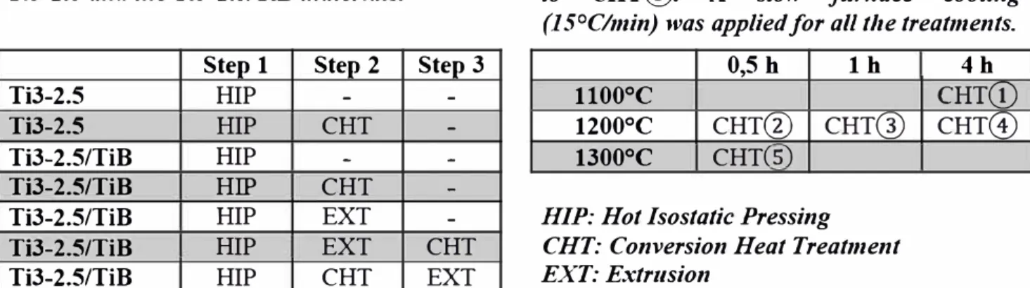
Table 1: Combination of the various thermomechanical steps used to produce the Ti3-2.5 and the Ti3-2.5/TiB materials.
Step 1 Step 2 Step 3
Ti3-2.5 HIP
-
-Ti3-2.5 HIP CHT
-Ti3-2.5/TiB HIP
-
-Ti3-2.5/TiB HIP CHT
-Ti3-2.5/TiB HIP EXT
-Ti3-2.5/TiB HIP EXT CHT
Ti3-2.5/TiB HIP CHT EXT
Table 2: Temperature and duration of the conversion heat treatments labelled CHT(D to CHT@. A slow furnace cooling (J 5°Clmin) was applied for ail the treatments.
0,5 h lh 1100°c
1200°c CHT@ CHT@
1300°C CHT(S)
HIP: Hot Isostatic Pressing
CHT: Conversion Heat Treatment EXT: Extrusion
4h
CHT(D CHTG)
The microstr11cture of the materials was investigated using Optical Microscopy (OM) and Scanning Electron Microscopy (SEM). The mechanical properties were evaluated using standard tensile tests, in order to get the Young's modulus E, the Yield Str·ength (YS), the Ultimate Tensile Str·ength
(UTS) and the plastic strain to failure (Ap). Turned test specimens with a gauge diameter of 6 mm and a gauge length of 34 mm (HIP and L extrusion) - or respectively 4 mm and 22 mm (LT extrusions) - were used. The values given are mean values, from 2 to 4 tensile test samples.
Results
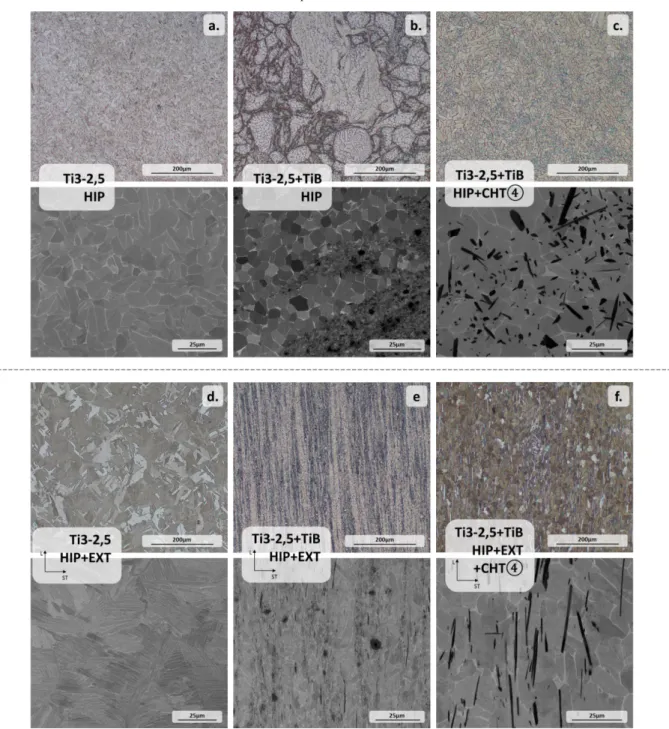
Microstructure. The microstructures of the unreinforced and the reinforced Ti3-2.5 at various steps of the processing route are illustrated Figure 2. For the unreinforced Ti3-2.5 alloy, the morphology of the α phase is nearly lamellar, with coarser lamellae in the as-HIP'ed condition (thickness ≈ 6 µm, Figure 2a), as compared to the as-extruded condition (thickness ≈ 1.5 µm Figure 2d). This difference is associated with the higher cooling rate after extrusion.
After HIPing the MA'ed composite powders, a heterogeneous microstructure is obtained (Figure 2b). Unreinforced regions are surrounded by regions with a high concentration of TiB2 particles, that have partially transformed into nanosized TiB needles (Length (L) ≈ 1 µm, Width (W) ≈ 100 nm), identified as the TiB-Bf phase [2][6][7]. Some remaining TiB2, surrounded by a reaction
TiB zone can also be identified. The unreinforced regions, made of agglomerated Ti3-2.5 powders, generally display a globular microstructure, although some isolated grains remained unaffected by the MA process and still display their initial coarse lamellar structure. The grain size in the unreinforced regions (up to 10 µm) is much larger compared to the reinforced regions (<1 µm). After the extrusion step, the microstructure is more homogeneous (Figure 2e). The previous unreinforced regions are present as highly elongated bands, some of them still retaining the initial coarse lamellar structure. The transformation of TiB2 particles into TiB needles proceeds further and some microscale TiB needles (L>10 µm, W>2 µm), identified as the TiB-B27 phase [2][6][7], were formed.
If a CHT is performed on the HIP'ed MMC (Figure 2c), the transformation of the TiB2 particles into TiB-B27 needles appears to be complete. The needles grow across the previous unreinforced regions, leading to a homogenisation of the microstructure. If a CHT is performed on the extruded MMC (Figure 2f), the same TiB-B27 needles are observed, but aligned in the extrusion direction, very likely as a consequence of the alignment of the precursor TiB-Bf needles during extrusion [2].
Only the micrographs for CHT④ are shown here. The five CHT conditions were studied. An increase of the needle size has been observed with the severity of the CTH (higher temperature and/or longer duration). These results will be published elsewhere [8].
The microstructure of the MMC in which the CHT was performed before extrusion has not yet been studied, but a similar evaluation of Ti-6242 matrix composites [9] indicates that the needles are shorter (as they were broken during extrusion) and that the matrix displays a full lamellar structure (due to the rapid air cooling after extrusion).
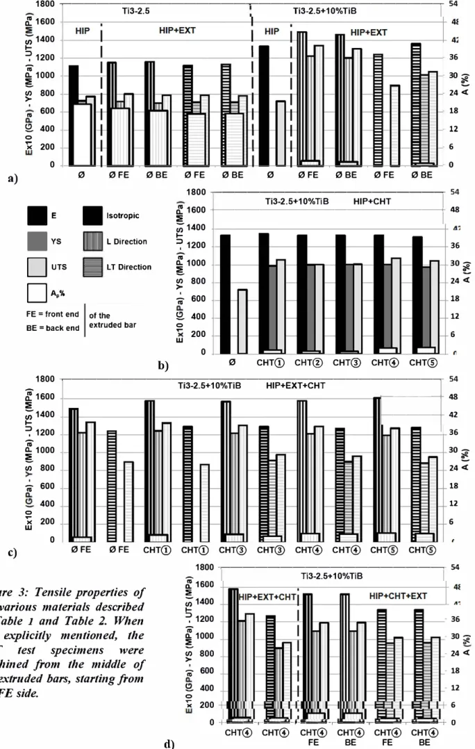
Mechanical Properties. The mechanical properties of the various materials are given in Figure 3. For the Ti-3-2.5 alloy (Figure 3a left), the properties are relatively homogeneous. Whatever the condition (as HIP'ed or extruded) and the location within the extruded bar (L or LT direction, back or front end), the variation is within 4%.
In the as HIP'ed condition, the increase in stiffness is important when adding the ceramic reinforcement (+20%), but the rupture occurs prematurely in the elastic domain (Figure 3a right). With a subsequent extrusion step, the stiffness further increases in the L direction (+33%) and the ductility in L direction is also improved (Ap between 1 and 2% for all test specimens). The results in the LT direction are more dispersed with lower values at the front end of the extrusion (and even premature failures in the elastic domain) compared to the back end.
Figure 3b shows the impact of the CHT conditions on the mechanical properties of the as-HIP’ed MMC. The CHT has limited impact on the stiffness, and the main impact is seen on the ductility, with values ranging from 0% (no CHT) up to 2.2% (CHT⑤). A good compromise between stiffness, strength and ductility can be found with the CHT④ (E=133 GPa, YS=1003 MPa, UTS=1015 MPa and Ap=2.0%).
For the extruded composite (Figure 3c), the application of a CHT increases the stiffness (+6-8 % whatever the CHT) in the L direction. The CHT has also a positive effect on the ductility, for both the L and LT direction: Ap increases respectively from 1.7 and 0% (no CHT) up to 3.1 and 2.9 (CHT⑤), but the YS and UTS values tend to be slightly lower for the most severe CHTs. A good balance of properties is again reached with CHT④ (E=158/127 GPa, YS=1212/899 MPa, UTS=1292/961 MPa, Ap=2.9/2.8% for respectively the L and LT directions).
Finally, Figure 3d compares the tensile properties of the MMC subjected to CHT④ before and after extrusion. The application of the CHT before extrusion leads to opposite consequences in L and LT directions. In the L direction, both the Young’s modulus, the YS and UTS are lower (4%, -10% and -8% respectively) and the ductility higher, whereas the contrary is observed in LT direction (+6% for the E, YS and UTS). The bar with CHT④ before extrusion displays more homogeneous properties (no difference between back end and front end), and limited differences between L and LT), reaching also a good balance of properties (E=152/134 GPa, YS=1094/958 MPa, UTS=1192/1020 MPa, Ap=4.4/2.6% for respectively the L and LT directions).
Figure 2: OM micrographs (on top) and SEM micrographs (on the bottom) of the various produced specimens described in Table 2.
1800 �---�---� 54 a) Ti3-2.5 � 1600 ;;; 1400 1-=? 1200
f
1000 � en >-' 800 "' 600 � 400 0...
)( 200 0 0 0 FE 0 BE■
E■
Isotropie■
YS L Direction□
UTS L T Direction□�•;,
FE = front end of the BE= back end extruded bar
b) 0 FE 1800 � 1600 :::!l: ;;;-1400 1-� 1200 � 1000 � en >-' 800 <i 600 � 400 0
...
200 w 0 0BE 0 Ti3-2.5+10%TiB0FE 0BE 0FE 0BE
36 30� e... 24 <C 18 12 6 0 �---� 54 Ti3-2. 5+10% Ti B HIP+CHT +---+48 0 CHT© CHT@ CHT@ CHT@ CHT@ 36 30� e... 24 <( 18 12 6 1800 �---� 54
f
1600 Ti3-2.5+10%TiB :::!l: ;;; 1400 1-=? 1200f
1000 � en 800 ' <i 600 400 0...
)( 200 w 0 HIP+EXT+CHT ---+ 48 ---+- 42 36 30� e... 24 <C 18 12 6 c) 0FE 0 FE CHT© CHT© CHT@ CHT@ CHT@ CHT@ CHT@ CHT@Figure 3: Tensile properties of the various materials described in Table I and Table 2. When not explicitly mentioned, the EXT test specimens were machined /rom the middle of the extruded bars, starting /rom the FE side. 1800 �---� 54 'i_ 1soo :::!l: ;;;-1400 � 1200 { 1000 en 800 >--;- 600 � 400 0 Ti3-2.5+10%TiB 36 30 � 24 <( 18 12
x
200 6 0+a_...._.,.._...._.,_. __ ,.. __ ,.. ___ ,..._--+O CHT@ CHT@ CHT@ CHT@ CHT@ CHT@ d) FE BE FE BEDiscussion and Conclusion
The impact of the processing route on the microstructure can be seen from a matrix and a reinforcement perspective. Regarding the matrix, the morphology of the α grains in the non-reinforced material changes from a near lamellar microstructure in the as-HIP’ed material, to a fully lamellar microstructure in the extruded material, with a limited impact on the mechanical properties. In the matrix of the composites, the α grains have a similar shape going from a globular morphology (as HIP'ed condition) to a globular/nearly lamellar one (after extrusion and/or CHT). However, the α grains size varies from <1 µm up to >10 µm, and the mechanical properties are more diverse.
From a reinforcement perspective (very likely the predominant one), their presence leads in all cases to an increase of the Young modulus. The HIP’ed composite has a brittle behaviour due to the remaining TiB2 particles and the poor distribution of the reinforcement. After extrusion or CHT, the ductility is increasing, thanks to the further transformation of TiB2, the homogenisation of the reinforcement distribution and the resulting bigger and fewer TiB needles. The extrusion process also induces an anisotropic behaviour of the composite (all properties are lower in the LT direction), due to the alignment of the TiB needles during extrusion (CHT before extrusion) or their growth in the extrusion direction (CHT after extrusion) [10]. The position of the extrusion process with regard to the heat treatment is also of importance. Applying the extrusion after the CHT is believed to result in shorter TiB needles, leading to a better ductility for the final material, though the Young’s modulus and the strength are both slightly lower in the L direction. Complementary quantitative analysis of the α and TiB grains sizes, the crystallographic texture, fracture surfaces and metallographic cross-sections of test specimens are under way to consolidate our understanding on the relationships between the matrix and reinforcement morphologies, the rupture mode and the tensile properties [8].
Finally, from a more industrial perspective, it has to be noted that some differences can be observed between the front end and the back end of the extruded bars, differences that will need further investigations for a complete understanding.
Additional investigation is required to further improve the properties and the robustness of the processing route. However, this study clearly demonstrates the possibility to produce, at an industrial scale, a ductile version of a highly reinforced titanium matrix composite, showing important application potential.
References
[1] T.W. Clyne, P.J. Withers, An Introduction to Metal Matrix Composites, Cambridge University Press, 1995. http://books.google.fr/books?id=8Yv8Mf1UkR0C.
[2] L. Ropars, PhD thesis, Composites à matrice titane et renforts TiB élaborés par métallurgie des poudres : cinétique de transformations des phases, formation des microstructures et propriétés mécaniques, Université de Lorraine (2016).
[3] J.-B. Fruhauf, J. Roger, O. Dezellus, S. Gourdet, N. Karnatak, N. Peillon, S. Saunier, F. Montheillet, C. Desrayaud, Materials Science and Engineering: A 554 (2012), pp. 22-32.
[4] T. Saito, JOM Journal of the Minerals, Metals and Materials Society. 56 (2004), pp. 33–36. [5] S. Gorsse, PhD thesis, De nouvelles approches sur les matériaux composites à matrice titane, Université de Bordeaux I, 1999.
[6] L. Ropars, M. Dehmas, S. Gourdet, J. Delfosse, D. Tricker, E. Aeby-Gautier, Journal of Alloys and Compounds 624 (2015), pp. 179-188.
[7] L. Ropars, M. Dehmas, S. Gourdet, J. Delfosse, D. Tricker, E. Aeby-Gautier, in: Proceedings of the 13th World Conference on Titanium, San Diego, USA, 2016: pp. 1211–1216.
[8] Phase Transformation kinetics, microstructure formation and mechanical properties of TiB reinforced titanium matrix composites, Paper in preparation.
[9] Unpublished results.