an author's https://oatao.univ-toulouse.fr/21351
https://doi.org/10.1109/CAMA.2018.8530601
Laquerbe, Vincent and Pascaud, Romain and Callegari, Thierry and Liard, Laurent and Pascal, Olivier Experimental study of a tunable sub-wavelength plasma-based VHF-UHF resonator. (2018) In: 2018 IEEE Conference on Antenna Measurements & Applications (CAMA), 3 September 2018 - 6 September 2018 (Västerås, Sweden).
Experimental study of a tunable sub-wavelength
plasma-based VHF-UHF resonator
Vincent Laquerbe and Romain Pascaud
Thierry Callegari, Laurent Liard, and Olivier Pascal
ISAE-Supaéro LAPLACE, CNRS, UPS, INP Université dé Toulouse Université dé Toulouse
31055 Toulouse, France 31400 Toulouse, France
Email: [email protected]
Abstract—In this paper, a tunable sub-wavelength resonator using a hemispherical plasma discharge is investigated at VHF- UHF frequencies. The overall setup is detailed. The resonance is experimentally investigated with an indirect method which consists in studying the influence of the plasma hemisphere on the transmission between two near-field monopole probes. The design presented here opens new perspectives for the realisation of plasma-based electrically small antennas thanks to a non-intrusive and adequate integration of the whole plasma control system below a ground plane.
Index Terms—Electrostatic resonator, Plasma devices. I. In t r o d u c t i o n
S
UB-WAVELENGTH particles are known to exhibit very peculiar resonant phenomena at optical frequencies [1]. For example, the quasi-static analysis of an electrically small sphere of dielectric constant e imersed in vacuum shows that its polarisability a, which represents its response to an incident static electric field E 0, is given by [2] :6 e — 1
a = 4 n a 6 (1)
e + 2 w
where a is the radius of the considered sphere. When e = - 2 , the polarisability a becomes theoretically infinite and reveals the electrostatic dipole resonance, also known as the localized surface plasmon resonance (LSPR). At microwave frequencies, it has been suggested to use this property for the realisation of efficient electrically small antennas by coupling such an ENG (for Epsilon NeGative) resonator to a feeding dipole or monopole-like probe [3], [4]. Practical implementations are based on metamaterials that exhibit negative permittivity in the microwave range [5], [6]. However, it was also suggested in [3], [4] to use plasma discharges to obtain ENG properties at microwave frequencies.
In this paper, a plasma-based electrostatic resonator is pre-sented. Its experimental characterisation is proposed by mea-suring its effect on the transmission between two monopole probes. Radiation enhancement and frequency tuning are ex-perimentally demonstrated.
(thereafter plasma) is ignited inside a hemispherical bell jar. The plasma relative permittivity follows the Drude model [7]:
£p (w ) = 1 - W
W (w + iv ) ’ with wp =
2 e2 n e
£o me (2)
where v, u p, e, n e, m e, and e0 are the electron collision frequency, the plasma angular frequency, the Coulomb charge, the electron density, the electron mass, and the vacuum per-mittivity, respectively. For a given operating angular frequency u , it is clear from (2) that within a dense plasma (i.e., when u p > u ), the dielectric constant becomes negative and a so- called ENG medium is created.
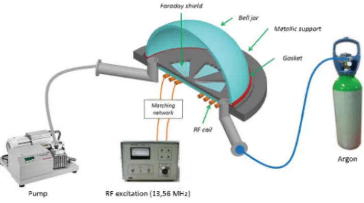
In our study, as shown in Fig. 1, the spherical resonator is replaced by a hemisphere above a ground plane. The jar is composed of a pyrex-like glass whose dielectric constant is equal to 5.5. Its outer diameter 2a is 215 mm (A/4.65 at 300 MHz) and it has a thickness of 5.5 mm. The inner gas composition and its pressure are controlled by a vacuum- sealed system, comprising a two stage pump and a gas bottle with controllable flow rate. Ignition power is then brought to the discharge through a Faraday shield thanks to a 4-turns inductive coil. The coil, placed below the Faraday shield and outside the sealed volume, is connected to a matching system and driven by a RF current at 13.56 MHz. The RF matching
Faraday shield Bell ja r Gasket Matching network RF coil Argon Metallic support Pump RF excitation (13,56 MHz) II. De v i c e a n d e x p e r i m e n t a l s e t u p
The experimental setup is presented in Fig. 1. A low pressure non-equilibrium non-magnetized plasma discharge
Fig. 1. Schematic of the experimental setup comprising gas management and RF plasma ignition systems. Except for gas inlet and outlet, only half of the structure is represented for clarity.
■40
Fig. 2. Photography of (a) the inductively coupled plasma discharge in the vacuum-sealed hemisphere and (b) the two monopole probes placed on an extended ground plane.
system is composed of two capacitors, mounted in parallel, that can be tuned to maximize the power transfer between the coil and the Inductively Coupled Plasma (ICP) discharge [8]. The Faraday shield has been designed numerically with Ansys HFSS and allows an efficient inductive energy coupling be-tween the coil and the discharge by suppressing the capacitive part, which generates more losses in the discharge [9].
The main advantage of the proposed design is that the vacuum generation system and the plasma ignition source are placed below the ground plane. Therefore, no other element is protruding above the ground plane except the resonator itself.
As can be seen from Fig. 2a, the resulting ICP dis-charges fills the entire hemispherical volume. It is also clear from Fig. 2a that the plasma is inhomogeneous, which is in fact the case for any discharge. Although homogeneous ENG structure has been considered in [3], [4], it has been recently shown analytically in [10] that a radially inhomogeneous spherical medium with a continuous profile might also excite the desired electrostatic resonance. In this case, the electron density at the center of the structure must be larger to balance its fall at outer interfaces.
III. Ex p e r i m e n t a l St u d y
The resonance of the plasma hemisphere is experimen-tally investigated with two identical monopole probes, placed symmetrically at a distance of 40 mm of the bell jar (see Fig. 2b). In order to minimize side effects, the ground plane has been extended beyond the probes and forms a metallic disk with an outer diameter of approximately 2 m. The probes radius is 1 mm and their length is 4 cm. They are soldered to N-type flange connectors that are directly connected to a Vector Network Analyser. The whole setup without plasma has been simulated with Ansys HFSS. The transmission coefficient between the two probes is presented in Fig. 3 and is in good agreement with measurements. At these frequencies, the transmission is low because the probes are inefficient, since their nominal operating band is rather expected around 1.875 GHz.
When a plasma discharge is ignited with the appropriate electron density, the transmission coefficient is strongly af-fected in the VHF-uHF, where its permittivity is negative. To quantify the influence of the plasma and its transmission enhancement, it is more interesting to consider the relative
Frequency (MHz)
Fig. 3. Simulated and measured transmission coefficients | | between the two probes when no plasma is ignited.
transmission coefficient A S 21, simply calculated as the differ-ence, in decibels, between the amplitude of the transmission coefficients with and without plasma, and defined by :
A S2i S21(p0
dB S. dB (3)
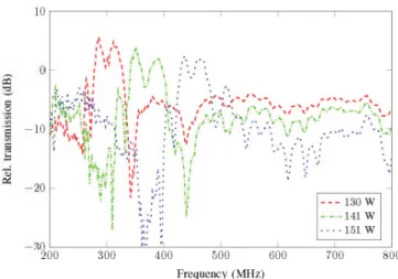
In this study, an argon plasma is considered at the pressure P = 5 mTorr (approximately 0.67 Pa). Fig. 4 represents A S 2i as a function of the frequency for various RF input power Pin injected to the coil. For each value of P in, A S 2i becomes locally positive. This transmission enhancement can be explained by the electromagnetic coupling occuring be-tween the two probes and the plasma discharge, which behaves as a resonator at these frequencies. At this pressure, the largest measured transmission enhancement reaches 5 dB and broadens over 50 MHz. The resonant frequency can now be tuned by simply adjusting the RF power. Indeed, as predicted by theoretical approaches, tuning the RF input power modifies the electron density inside the discharge. This modification of the electron density changes the dielectric constant, which in turn, tunes the resonant frequency. From Fig. 4, it can be seen that a large tuning capability is achieved through a RF power range of 20 W. The measured frequency agility varies roughly linearly with P in . At this pressure, it has been observed that the current device could not be operated for lower values of P in , since the discharge would simply extinguish.
In addition, the influence of the inner pressure is now investigated. The RF input power is set equal to P in = 138 W and the pressure P varies. The corresponding relative trans-mission coefficients are shown in Fig. 5. In this case, the transmission between the two probes is again amplified and reflects the excitation of the electrostatic resonance. Varia-tions of inner pressure also provide frequency agility of the resonance. Indeed, when P varies, the number of particles that can be ionized to create electron changes, which allows to control n e. However, this method might not be desired for frequency tuning because the pressure directly affects the
10
-10
200 300 400 500
Frequency (MHz)
600 700 800
Fig. 4. Relative transmission coefficients A S 2i measured at P = 5 mTorr for various RF input power Pi n .
pq ’S ö _o I s "03 OS 10 10 20 30 o IV t v 'M 1 » . f •' ,i! . j ! 1 ' i .i > y ; :
ÿjjJh.i
, ! ' i f U U- it! : !I, jil
. . . i V . ' ¿ V Y ; / V . . . . - v . - v A - ■ A • : ■ V / V i / v ' \ i \ : v I l ; ' p • j . ? : !. iÜ i Ü Ü If, j: 4 mTorr i 1 1 5 mTorr 6 mTorr ; t i 7 mTorr 200 300 400 500 Frequency (MHz) 600 700 800 0The ENG resonance has been demonstrated using a two probes system that measures the influence of the discharge on the transmission coefficient. Despite the non-negligible electrical size (ka at least equal to 0.58) of the structure, transmission amplifications were measured up to 10 dB, which suggests very large amplification can be obtained for smaller ka. The main limitation of the current prototype remains its reliability in the VHF band. So far, no resonance was observed below 260 MHz as no stable discharge could be sustained at both low input power and low inner pressure. Further work is needed to overcome this limitation and create highly miniature resonator at VHF frequencies and beyond.
This original implementation of the LSPR using plasma discharge can be further extended to other frequency band as long as the plasma electron density follows accordingly, as stated by (2) and the value of the ratio wp/w. By coupling a simple probe to this resonator, one may create a miniature ENG structure that radiates efficiently, as initially suggested in [3], [4]. The prototype developed in this paper might be well suited for this application, thanks to its placement above a ground plane. A hermetically-sealed coaxial probe, placed at the center of the sphere and terminated by a monopole, could bring the microwave power to be radiated. The symmetry of the structure may ease its mechanical integration and isolate the RF power (used to sustain the discharge) from the signal of interest feeding the monopole itself. Such an electrically small antenna will exhibit interesting electrical properties like furtivity (when no discharge is ignited) and frequency agility (with the plasma on).
V. A C K N O W LED G EM EN T
The authors would like to thank the French Defence Agency (DGA) for its financial support.
Fig. 5. Relative transmission coefficients A S 2i measured at Pin = 138 W for various gas pressure P .
electron collision frequency v [7], and so the ohmic losses in the discharge. Thus, larger values of P increase losses. As long as the discharge can be sustained for relatively low value of input power Pin, an inner pressure P as low as possible shall be preferred. Similarly, the pressure plays a significant role in the amplitude of the resonance. Fig. 5 indeed highlights a stronger transmission enhancement for the lowest values of pressure (up to 10 dB enhancement at P = 4 mTorr), due to lower ohmic losses in the discharge. The same extinction issue has been observed as before and the inner pressure could not be lowered as the discharge would also shut down.
IV. Co n c l u s i o n a n d Di s c u s s i o n s
In this paper, a novel hemispherical electrostatic resonator has been developed in the VHF-uHF band using a plasma discharge. The plasma here acts as an ENG medium and its parameters (RF input power P in and discharge pressure P ) can be adjusted to achieve frequency tuning.
Re f e r e n c e s
[1] C. F. Bohren and D. R. Huffman, Absorption and Scattering o f Light
by Small Particles. John Wiley & Sons, 1983.
[2] A. Sihvola, “Character of surface plasmons in layered spherical struc-tures,” Prog. Electromagn. Res., vol. 62, pp. 317-331, 2006.
[3] R. Ziolkowski and A. Erentok, “Metamaterial-based efficient electrically small antennas,” IEEE Trans. Antennas Propag., vol. 54, no. 7, pp. 2113-2130, Jul. 2006.
[4] H. R. Stuart and A. Pidwerbetsky, “Electrically small antenna elements using negative permittivity resonators,” IEEE Trans. Antennas Propag., vol. 54, no. 6, pp. 1644-1653, Jun. 2006.
[5] D. Smith, D. Vier, S. N.-N. W. Padilla, and S. Schultz, “Loop-wire medium for investigating plasmons at microwave frequencies,” Appl.
Phys. Lett., vol. 75, no. 10, pp. 1425-1427, 1999.
[6] H. Stuart and C. Tran, “Subwavelength microwave resonators exhibiting strong coupling to radiation modes,” Appl. Phys. Lett., vol. 87, p. 151108, 2005.
[7] M. A. Lieberman and A. J. Lichtenberg, Principles o f Plasma
Dis-charges and Materials Processing. John Wiley & Sons, 2005. [8] F. F. Chen, “Capacitor tuning circuits for inductive loads,” UCLA Report,
no. PPG-1401, 1992.
[9] L. J. Mahoney, A. E. Wendt, E. Barrios, C. J. Richards, and J. L. Shohet, “Electron-density and energy distributions in a planar inductively cou-pled discharge,” J. Appl. Phys., vol. 76, no. 4, pp. 2041-2047, Aug. 1994.
[10] V. Laquerbe, R. Pascaud, T. Callegari, L. Liard, and O. Pascal, “Analyti-cal model to study the electrostatic resonance of subwavelength radially inhomogeneous negative permittivity spheres,” IEEE Antennas Wireless