HAL Id: hal-01649396
https://hal.archives-ouvertes.fr/hal-01649396
Submitted on 27 Nov 2017HAL is a multi-disciplinary open access
archive for the deposit and dissemination of sci-entific research documents, whether they are pub-lished or not. The documents may come from teaching and research institutions in France or abroad, or from public or private research centers.
L’archive ouverte pluridisciplinaire HAL, est destinée au dépôt et à la diffusion de documents scientifiques de niveau recherche, publiés ou non, émanant des établissements d’enseignement et de recherche français ou étrangers, des laboratoires publics ou privés.
Lumped Parameter Thermal Model of Permanent
Magnet Synchronous Machines
Sarah Touhami, Yves Bertin, Yvan Lefèvre, Jean-François Llibre, Carole
Hénaux, Matthieu Fénot
To cite this version:
Sarah Touhami, Yves Bertin, Yvan Lefèvre, Jean-François Llibre, Carole Hénaux, et al.. Lumped Parameter Thermal Model of Permanent Magnet Synchronous Machines. Electrimacs 2017, Jul 2017, Toulouse, France. pp. 1-6. �hal-01649396�
This is an author-deposited version published in:
http://oatao.univ-toulouse.fr/
Eprints ID: 18499
O
pen
A
rchive
T
oulouse
A
rchive
O
uverte (
OATAO
)
OATAO is an open access repository that collects the work of Toulouse
researchers and makes it freely available over the web where possible.
To cite this version: Touhami, Sarah and Bertin, Yves and Lefèvre, Yvan
and Llibre, Jean-Francois and Henaux, Carole and Fenot, Matthieu
Lumped Parameter Thermal Model of Permanent Magnet Synchronous
Machines. (2017) In: Electrimacs 2017, 4 July 2017 - 6 July 2017
(Toulouse, France)
Any correspondence concerning this service should be sent to the repository administrator:
[email protected]
L
UMPED PARAMETER THERMAL MODEL OF PERMANENT MAGNET
SYNCHRONOUS MACHINES
S. Touhami
1,Y. Bertin
2,Y. Lefèvre
1, J. F. Llibre
1, C. Henaux
1, M. Fénot
21. LAPLACE, CNRS, University of Toulouse, Toulouse 31000, France.
2. P’ Institute, CNRS, ENSMA, University of Poitiers, UPR 3346, 1 Avenue Clément Ader, BP 40109, 86961 Futuroscope Chasseneuil, France.
e-mail: {stouhami, lefevre, jean-francois.llibre, henaux}@laplace.univ-tlse.fr
{yves.bertin, matthieu.fenot}@ensma.fr
Abstract – This paper describes a thermal equivalent circuit of Liquid Cooling
Totally Enclosed Permanent Magnet Synchronous Machines (LCTE-PMSMs). Conductive heat transfer in all directions is taken into account. Specific care has been taken to represent them by equivalent circuit. The conductive heat transfer in heterogeneous media like slots and the convective heat transfer in the airgap and the end-winding are studied.
Keywords – Permanent magnet synchronous machines, thermal equivalent circuit,
convection heat transfer, conduction heat transfer, lumped parameter, homogenization, heat sources, thermal conductivity.
1. INTRODUCTION
It is known that excessive temperatures decrease the motor life expectancy. Therefore thermal modeling is very important in the design of electrical machines. According to [1], radiative heat transfer induces in most cases negligible consequences inside the rotating electrical machines. For practical convenience and structural reasons, lumped parameter thermal models are commonly used [1][2]. Theses models are very suitable for conduction phenomena. In radial flux machines where many parts of the machine have cylindrical forms, T-block can be used to model different parts of the machine such as yokes [2]. Nevertheless conduction phenomena are not easily modeled when heteregenous media are involved. For instance, the thermal modeling of slots in electrical machines are still under investigations: according to the purpose of the models several types of thermal models for slot are available [3]-[5]. Lumped parameter models are also used for the modeling of convective heat transfer exchanges in electrical machines. Convection in airgap, end-winding and at end space constitutes a very active research area. In airgap the heat transfer is due to the air flow between the rotor and the stator. Different types of air flow can be distinguished [6][7]:
- smooth airgap without axial flow: this case exists when the electric machine is closed. The flow in airgap is named Taylor-Couette flow, - smooth airgap with an axial flow combined with
rotation of the rotor: in contrast of previous case this configuration exists when the machine is
open. The flow in airgap is known as Poiseuille-Taylor-Couette flow,
- slotted airgap with or without axial flow: in this case the flow structure can be similar to Taylor-Couette flow or to Taylor Taylor-Couette-Poiseuille flow.
Convective and conductive heat transfer studies at end-winding are presented in [8] and [9] respectively. The flow fluid and the convective heat transfer between rotor surface and end-cap surface are studied in [10][11].
This paper will present a thermal model of Liquid Cooling Totally Enclosed Permanent Magnet Synchronous Machines (LCTE–PMSMs). This model takes into account convection and conduction heat transfers in all directions.
2. LUMPED PARAMETER THERMAL MODEL
OF PERMANENT MAGNET SYNCHRONOUS MACHINES
One of the methods of thermal study of electrical machines is the nodal approach. This approach is based on a model with an equivalent electrical network of thermal resistances and capacitances. It gives the mean temperatures inside the modeled structure. Fig. 1 shows a radial cut of LCTE– PMSM. In this lumped parameter thermal model, some assumptions are made:
- the structure of the motor is closed,
- bearings are not taken into account in the thermal model,
- shaft is assumed to be non-dissipative,
- motor is assumed symmetric in axial direction; the thermal model of LCTE-PMSM is carried out for middle section,
- conductors in slot are uniformly distributed, - the slot consists of a group of insulated
conductors, surrounded by a main insulation layer,
- only iron losses in stator magnetic core and Joule losses in winding are taken into account in the thermal model given that these losses are the most very important.
Fig. 1. Radial cut (middle section) of LCTE-PMSM for the thermal modeling [4].
3. HEAT TRANSFER
To study thermal behavior of an electrical machine by modeling, it is required to distinguish three elements: the heat transfer, the heat storage and the heat generation. Heat transfer is generally modeled by thermal resistances of conduction or convection according to heat transfer mechanism. The heat storage is modeled by thermal capacitance. Heat generation is related to losses such as iron and Joule losses.
3.1. CONDUCTION HEAT TRANSFER A. Heat conduction equation
By carrying an energy balance between internal heat produced, heat induced by variation of temperature and which is exchanged in boundaries, equation of heat transfer in isotropy region takes the following form: )) ( grad ( div T p t T cp (1)
Where: cp is the specific heat, is the density, p is
the heat generation density, is the thermal conductivity and T is the temperature.
B. Modeling of heterogeneous parts
In order to take into account thermal aspects of heterogeneous parts of electrical machines such as windings and iron core, one of the methods is to homogenize theses parts and to evaluate equivalent thermal conductivities req and aeq respectively in
radial and axial directions, equivalent density e and
equivalent specific heat cpe. According to [3]-[5],
homogenization formulas used for evaluated radial and axial conductivities, equivalent density and equivalent specific heat are:
- heterogeneous parts with two phases:
e p p p e i i i eq a eq r c c c v e 2 2 2 1 1 1 2 2 1 1 2 1 1 2 1 1 2 1 ) 1 ( ) 1 ( 1 1 1 (2)
- heterogeneous parts with three phases:
e p p p p e i i i eq a eq r c c c c v e 3 3 3 2 2 2 1 1 1 1 2 3 2 1 2 3 2 1 2 3 2 1 1 1 1 3 2 1 2 3 3 2 2 1 1 3 2 2 2 2 2 3 2 2 2 3 3 2 2 (3)
Where 1, 2, 3 are the fill factors (with i=Si/Sslot
i=1,2,3 and 1 2=1 for two phases and 1 2 3=1 for three phases), 1, 2, 3 are the
thermal conductivities, cp1, cp2, cp3 are the specific
heats, vi is the volume proportion of constituents i
in axial direction and i is the thermal conductivity
of constituents i.
C. Thermal Resistance
For monodimensional conductive heat transfer through solid wall in rectangular geometry (see Fig. 2), thermal resistance is expressed by:
S l
Rcond (4)
Where: l is the thickness of the wall, S is the area of the wall and is the thermal conductivity of the wall. For cylindrical geometry with heat transfer, thermal resistances are calculated from equation (1) in cylindrical coordinates (see Fig. 2):
) ( 1 ln 2 2 1 ln 2 1 2 1 2 2 2 1 3 2 1 2 2 2 1 2 1 2 2 1 2 2 2 1 2 2 1 r r L R r r r r r L R r r r r r L R (5)
Where: L is the length of cylinder, is the angle of cylinder part and r1, r2 are inner and outer cylinder radius. In the case of cylindrical geometry without heat source, the thermal resistances are given by:
) ( : Axial ln 1 : Radial 2 2 2 1 2 2 1 1 r r L R r r L R (6) (a) (b) Fig. 2. (a) Lumped parameter of rectangular geometry (b) Lumped parameter of a hollow
D. Thermal capacitance
Some of the heat transferred or produced is stored in the materials of the structure in terms of their mass calorific capacity cp. The thermal capacitance
therefore depends on the type of materials. For a material of volume V, of mass calorific capacity cp
and of density , the thermal capacitance C is equal to:
V c
C p (7)
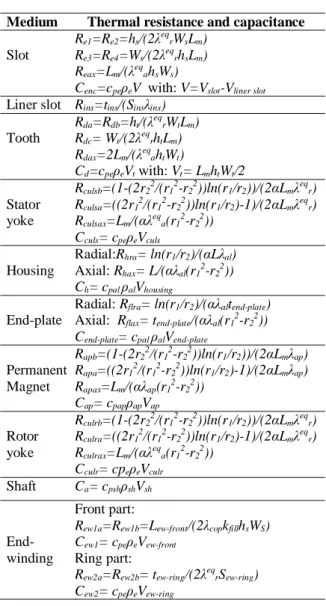
By using equations (4), (5), (6) and (7), we summarized in Table I, the lumped parameter thermal of heat conduction in the different parts of the LCTE-PMSM.
Table I. Lumped Parameter Thermal of Heat Conduction Transfer
Medium Thermal resistance and capacitance
Slot
Re1=Re2=hs/(2 eqrWsLm)
Re3=Re4=Ws/(2 eqrhsLm)
Reax=Lm/( eqahsWs)
Cenc=cpe eV with: V=Vslot-Vliner slot
Liner slot Rins=tins/(Sins ins)
Tooth Rda=Rdb=ht/( eqrWtLm) Rdc= Wt/(2 eqrhtLm) Rdax=2Lm/( eqahtWt) Cd=cpe eVt with: Vt= LmhtWt/2 Stator yoke Rculsb=(1-(2r22/(r12-r22))ln(r1/r2))/(2 Lm eqr) Rculsa=((2r12/(r12-r22))ln(r1/r2)-1)/(2 Lm eqr) Rculsax=Lm/( eqa(r12-r22)) Cculs= cpe eVculs Housing Radial:Rhra= ln(r1/r2)/( Lal) Axial: Rhax= L/( al(r12-r22)) Ch= cpal alVhousing End-plate
Radial: Rflra= ln(r1/r2)/( altend-plate)
Axial: Rflax= tend-plate/( al(r12-r22))
Cend-plate= cpal alVend-plate
Permanent Magnet Rapb=(1-(2r22/(r12-r22))ln(r1/r2))/(2 Lm ap) Rapa=((2r12/(r12-r22))ln(r1/r2)-1)/(2 Lm ap) Rapax=Lm/( ap(r12-r22)) Cap= cpap apVap Rotor yoke Rculrb=(1-(2r22/(r12-r22))ln(r1/r2))/(2 Lm eqr) Rculra=((2r12/(r12-r22))ln(r1/r2)-1)/(2 Lm eqr) Rculrax=Lm/( eqa(r12-r22)) Cculr= cpe eVculr Shaft Ca= cpsh shVsh End-winding Front part:
Rew1a=Rew1b=Lew-front/(2 copkfillhsWS)
Cew1= cpe eVew-front
Ring part:
Rew2a=Rew2b= tew-ring/(2 eqrSew-ring)
Cew2= cpe eVew-ring
3.2. CONVECTION HEAT TRANSFER A. Convection heat transfer in airgap
For an airgap without axial flow, convective resistance is from the rotor to the stator.The nature of airgap flow depends on modified Taylor number
Tam, which characterizes the rotation influence. It is
evaluated by the following equations [6][7]:
g a am F T (8) With: 2 3 2Re m a (9) 2 4 2 / 1 1697 1 m g R e P F (10) x x P 625 . 0 1 00056 . 0 625 . 0 1 0571 . 0 (11) m m R e R e x 2 / 1 / (12) Where: is the rotational speed, Rm isthe mean
radius, e is the airgap thickness, is the kinematic viscosity.
Taking the case where airgap is smooth without axial flow, the flow is [6][7]:
Stable and laminar when Tam < 1700,
Laminar with the appearance of Taylor vortices for 1700 < Tam <104,
Laminar with Taylor vortices, but the space of evolution changes slightly for Tam > 104.
The flow in airgap is also modeled by the convective heat transfer coefficient h (W.m-2.K-1):
h
D Nu
h (13)
Where: is the thermal conductivity. For flow between concentric cylinders such as in the airgap:
Dh=2e. The nusselt number Nu proposed by
“Bercker et Kaye 1962” and used by most authors [1], [2] and [7] are: 7 4 241 . 0 4 367 . 0 10 0 1 for 409 . 0 10 1700 for 128 . 0 1700 0 for 2 am am am am am T T Nu T T Nu T Nu (14)
B. Convection heat transfer in end-windings
The general empiric formulation of convective heat transfer coefficient given in literature [2][8] is:
3 2 11 k v k k h (15)
Where: v is the speed of air around end-windings,
k1 characterizes natural convection, k2 and k3 characterize forced convection and h is the average convective heat transfer coefficient.
Table II. Correlation of Convective Heat Transfer Coefficient Around End-winding
Correlations k1 k2 k3 [2] 41.4 0.15 1 [3] 15.5 0.29 1 [8] 15.5 0.39 1
C. Convection heat in end cap of rotor
According to [11], the intensity of the air convection heat transfer within the end-space
between the rotor and frame is affected by the speed rotation of the rotor. Due to the high-speed, the flow state of air near the rotor can be turbulent. The flow on the frame surface is laminar. According to [10], the convective heat transfer coefficient on rotor lateral surfaces is calculated by:
h D Nu h . . Re Re Nu . . Re Re Nu / 10 6 3 10 5 2 for 0196 . 0 10 5 3 10 8 1 for 3286 . 0 5 5 8 . 0 5 5 5 . 0 (16)
Where: Re is the Reynolds number (Re=r² ), r is the rotor radius and Dh is the hydraulic diameter.
D. Thermal resistance
The convective thermal resistance is defined as:
hS Rconv
1 (17)
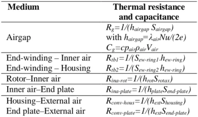
Where: S is the surface of convective heat transfer. Table III summarizes the lumped parameter of convection heat transfer.
Table III. Lumped Parameter Thermal of Convection Heat Transfer
Medium Thermal resistance and capacitance
Airgap
Rg=1/(hairgap Sairgap)
with hairgap airNu/(2e)
Cg=cpair airVair
End-winding – Inner air End-winding – Housing
Rtb1=1/(Sew-ring1-hew-ring)
Rtb2=1/(Sew-ring2 hew-ring)
Rotor–Inner air Rina-rot=1/(hrotSrotax)
Inner air–End plate Rina-plate=1/(hplateSend-plate)
Housing–External air End plate–External air
Rconv-hous=1/(hextShousing)
Rconv-plate=1/(hextSend-plate)
Fig. 3 shows the sketch of thermal model of a portion of an angle of representation of LCTE-PMSM. The heat sources come from Joule losses and iron losses of this portion.
Fig. 3. Sketch of lumped parameter thermal model of LCTE-PMSM.
3.3. HEAT SOURCES
Losses in PMSM constitute the heat sources which contribute to the increase in temperature.The main losses in the PMSMs are the Joule losses in winding and the iron losses in stator magnetic core. They are expressed by the following equations : - Joule losses rms rms rot hw joule k S A J P (18)
Where: khw is the head winding coefficient (ratio
between the length of half turn and the active length), is the electric resistivity, Srot is the
external rotor surface, Arms is the linear current
density and Jrms is the current density.
- Iron loss (Bertotti’s model) [10]
5 . 1 2 2 ( ) ( ) m e m c m h Iron k fB k fB k fB P (19)
Where: kh is the hysteresis loss coefficient, kc is the
eddy current coefficient, ke is the excess loss
coefficient, f is the frequency and Bm is the
maximum magnetic induction.
3.4. LUMPED PARAMTER THERMAL MODEL RESULTION
The lumped parameter thermal model (Fig. 3) presented with N Nodal temperatures, can be expressed with energy balance for each node:
P T R dt T d C 1 (20) Where: [T] is the temperature vector, [C] is the thermal capacitance matrix, [R] is the thermal resistance matrix, and [P] is the heat source vector. Using Kirchhoff’s circuit laws, the resolution of lumped parameter thermal model can be simplified by equation (21). ext t tT P I R V T I R I dt T d C 1 1 (21)
Where: [I] is the incidence matrix and [V] is the incidence vector for reference node which represented by the ambient air temperature Text.
4. APPL CAT ON
The report of T. A. Burress in [11] publishes detailed data of hybrid electric vehicle (HEV) in 2011. In this report, the Lexus LS600h has the highest specific power of 2.46kW/kg. Taking this example, a PMSM with a specific power of 3kW/kg with the same rated power and speed as the Lexus LS 600h has been sized using Slemon’s model [12]. Tables IV, V and VI give the sizes of the motor, the heat sources of the thermal model and the material thermal properties. Table VII shows heat transfer coefficients that must be imposed in order to have the winding temperature within acceptable range: 120°C-130°C.
This result shows that for a PMSM with 3kW/kg the heat transfer coefficients are already large compared to those found in literature [2] and [13] for indusrial motors.
A second PMSM with a specific power of 5kW/kg and the same rated power has been also sized. In order to reach this last specific power, the speed, the tangential stress and some other assumptions must be changed (see Table IV). Table V shows the new values of heat sources. Necessary heat transfer coefficients to have winding temperature within acceptable range are given in Table VII. It can be noticed that the heat transfer coefficient of the housing external surface has to be increased of about 50%.
Table IV. Main Dimensions and Parameters of LCTE-PMSM Motor part PMSM 3kW/kg PMSM 5kW/kg Power P [kW] 110 110 Speed N [rpm] 4500 5500 Number of poles 2p 8 8 Number of slots Ns 48 48 Number of phases q 3 3 Tangential stress t [kPa] 85 148.5
Current density j[A/mm²] 12 12 Max airgap flux density Bgm[T] 1.02 1.02
Tooth flux density Bt [T] 1.5 1.8
Yoke flux density By [T] 1.5 1.8
Outer frame radius Rf [mm] 119.18 102.65
Outer stator yoke radiusRy[mm] 107.7 92.26
Inner stator radius Rs[mm] 59.21 45.98
Active length Lm[mm] 124.6 96.80 Frame length L[mm] 174.4 135.5 Yoke height hy[mm] 10.06 6.51 Slot height hs[mm] 38.48 39.76 Slot width Ws[mm] 4.4 3.8 Tooth width Wt [mm] 3.4 2.2 Airgap thickness e [mm] 1.18 0.92 PM thickness tpm[mm] 4.19 3.25 Shaft radius Rsh[mm] 43.77 35.3
Motor weight Wmot [kg] 35.34 21.33
Total Joule losses Pj [kW] 2.651 2.793
Total Stator Iron losses Piron[W] 541.2 475.3
Table V. Heat Sources of Lumped Parameter Thermal Model of LCTE-PMSM
Motor part PMSM
3kW/kg
PMSM 5kW/kg
Stator Slot Pjs [W] 19.73 20.79
End-winding: front part Pew1[W]
End-winding: ring part Pew2[W]
3.80 4.09 5.31 3.01 Stator yoke Psy[W] 2.89 2.32 Stator tooth Pst[W] 2.76 2.64
Permanent Magent PPM[W] Neglected Neglected
Rotor yoke Pry[W] Neglected Neglected
Table VI. Thermophysical properties of materials used in LCTE-PMSMs Material thermal conductivity [W/(m.K)] specific heat [kJ/kg.K] density [kg/m3] Vacoflux48 rad/tang : 46 axial : 0.6 0.46 8120 Copper 360 0.39 8920 Sm2Co17 10 0.35 8300 Aluminum 209 0.9 2700 Stainless 17 0.465 7900 Air 0.025 1 1.177 Epoxy 0.5 - 1500 LordSC320 3.2 - - Table VII. Convection Heat Transfer Coefficients
Convection heat transfer
[W/(m².K)] PMSM 3kW/kg PMSM 5kW/kg Housing hext 222.1 340 Airgap hairgap 66.8 74
Rotor–Inner air hrot 22.6 25
End-plates-Inner air hplate 10 10
End-winding hew-ring 130 130
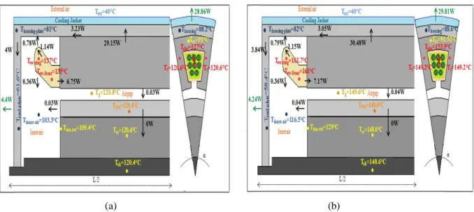
The simulation results of lumped parameter thermal model of LCTE-PMSMs are shown in Fig. 4. The temperatures of the hot media such as the slot and the end-winding remain above 130°C for LCTE-PMSM with specific power of 3kW/kg and greater than 150°C for LCTE-PMSM with specific power of 5kW/kg. A large part of the losses is evacuated through the cooling system placed on the surface housing by forced convection and a small part of losses is evacuated by natural convection through the end-plate. Therefore, for a specific power of 5kW/kg, the cooling effort must be further improved in order to have an acceptable temperature in the winding (see convection heat transfer values hext in Table VII).Results on Fig.4
can help to determine where the cooling effort must be done.
CONCLUSION
The thermal model described in this paper is an improvement of the calculation of lumped parameters for a Liquid Cooling Totally Enclosed Permanent Magnet Synchronous Machine (LCTE-PMSM). It takes into account conductive heat transfer in slots and teeth, stator and rotor yokes, end-windings and permanent magnets. It also takes into account convective heat transfer in airgap, housing, end-plates, end-windings, inside and outside of the machine. The main heat sources considered in this study are Joule and iron losses. The studied applications show one of the uses of the proposed approach: evaluation of the cooling effort to be done in order to reach a given level of specific power.
ACHNOWLEDGEMENT
This project has received funding from the [European Union’s Horizon 2020 (Cleansky 2JTI) research and innovation programme, 2014-2024] under grant agreement No 715483.
REFERENCES
[1] J. Nerg, M. Rilla, J. Pyhönen, Thermal Analysis of Radial-Flux Electrical Machines with a High Power Density, IEEE Trans. On Industrial Electronics, vol. 55, no. 10, pp. 3543-3554, October 2008.
[2] A. Boglietti, A. Cavagnino, Analysis of the End winding Cooling Effects in TEFC Induction Motors, IEEE Trans. On Industry Applications, vol. 43, no. 5, pp.1214-1222, Sept 2007. [3] A. Boglietti, A. Cavagnino, M. Lazzari, M.
Pastorlli, A simplified thermal model for variable speed self-cooled induction motor, IEEE Trans. On Industry Applications, vol. 39, no. 4, pp.945-952, July/August 2003.
[4] A. Fasquelle, Contribution à la modélisation multi-physique: électro-vibro acoustique aérothermique de machines de traction, PhD thesis, Ecole Central de Lille, 30 November 2007.
[5] M. Fénot, Y. Bertin, E. Dorignac, G. Lalizel, A review of heat transfer between concentric rotating cylinders with or without axial flow, International Journal of Thermal Sciences, Elsevier, vol. 50, issue 7. pp. 1138–1155, July 2011.
[6] D. A. Howey, Peter R.N. Childs, A. S. Holmes, ‘Air-gap convection in rotating electrical
machines’, IEEE Trans. On Industrial Electronics, vol. 59, no.3, March 2012.
[7] L. Idoughi, X. Mininger, F. Bouillault, L. Bernard and E. Hoang, Thermal Model with winding Homogenization and FIT Discretization for Stator Slot, IEEE Trans. On Magnetics, vol. 47, no. 12, pp.4822 4826, December, 2011.
[8] P. H. Mellor, D. Roberts, D.R. Turner, Lumped parameter thermal model for electrical machines of TEFC design, IEE Proceedings-B, vol. 138, no. 5, September 1991.
[9] B. Zhang, R. Qu, J. Wang, W. Xu, X. Fan, Y. Chen, Thermal model of totally enclosed water-cooled permanent magnet synchronous machines for electric vehicle application, IEEE Trans. On Industry applications, vol. 51, no. 4, pp. 3020-3028 July/August, 2015.
[10] G. Bertotti, General Properties of Power Losses in soft Ferromagnetic Materials, IEEE Trans. On Magnetics, vol. 24, no. 1, pp. 621-630, January 1988.
[11] T. A. Burress et al, Evaluation of the 2010 Toyota Prius Hybrid Synergy Drive System, Technical Report of Oak Ridge National Laboratory,March2011,https://www.osti.gov/sc itech/biblio/1007833.
[12] G. R. Slemon, On the Design of High-Performance Surface-Mounted PM Motors, IEEE Trans. On Industry Applications, vol. 30, no. 30, pp.134-140, January/February, 1994. [13] D. A. Staton, A. Cavagnino, Convection heat
transfer and flow calculations suitable for electric machines thermal models, IEEE Trans. On Industrial Electronics, vol. 55, no. 10, pp.3509-3516, October 2008.
(a) (b)
![Fig. 1. Radial cut (middle section) of LCTE-PMSM for the thermal modeling [4].](https://thumb-eu.123doks.com/thumbv2/123doknet/14380353.505892/4.892.110.416.251.494/fig-radial-middle-section-lcte-pmsm-thermal-modeling.webp)