© ASMDO 2008
DOI: xx.xxxx/ijsmdo:xxxxxxx
http://www.ijsmdo.org
Recent progress in the optimal design of composite structures:
in-dustrial solution procedures on case studies
Michael Bruyneel1,a, Benoît Colson1, Philippe Jetteur1, Caroline Raick1, Alain Remouchamps1, Stéphane Grihon2 1SAMTECH s.a., Liège Science Park, 8 Rue des chasseurs-ardennais, 4031, Angleur, Belgium
2 Airbus France, 316 Route de Bayonne, 31060, Toulouse, France
Received xx xx 20xx, Accepted xx xx 20xx
Abstract – In this paper, recent developments carried out in the SAMCEF finite element code and in the BOSS quattro optimization toolbox are presented. Those developments aim at simulating high non linear effects in laminated composite structures (post-buckling, collapse, delamination) and at optimising the composites with respect to those structural re-sponses. The use of Sequential Convex Programming and of Surrogate-Based Optimization methods is discussed on indus-trial optimization problems.
Key words: optimization methods, composite structures, industrial application, delamination
a
Corresponding author: [email protected]
1 Introduction
In order to decrease the lead time, virtual testing and numeri-cal optimization techniques are increasingly used in the dif-ferent fields of engineering. This is especially the case for composite structures, where two main issues have recently been identified. Firstly, reliable methods are required to ana-lyse post-buckling [1], collapse and delamination, which is a specific failure mode of laminated structures [2]. Secondly, designing real composite structures such as aircraft wings implies handling a large number of design variables and re-strictions, resulting in a large scale optimization problem that is difficult to both define and solve [3]. Moreover, local op-timization of aircraft components should involve advanced non linear analyses simulating delamination, post-buckling and collapse.
This paper presents an overview and a synthesis of the so-lution procedures recently developed in the SAMCEF finite element code [4] and in the BOSS Quattro multidisciplinary optimization platform [5] for solving such problems at an industrial level. The advanced buckling and collapse analysis capabilities are first presented, together with a discussion on the related sensitivity analyses, and an approach to evaluate delamination risks [6]. Then two optimization techniques used in this paper are recalled: a specific Sequential Convex Programming algorithm [7] and a Surrogate-Based Optimiza-tion method [8]. Finally, three applicaOptimiza-tions are presented. The first one tackles the optimization of laminates with re-spect to damage tolerance considerations, based on a detailed (high fidelity) analysis of delamination. The second one aims at designing composite structures to withstand buckling and collapse [9,10]. The last application presents the results ob-tained for the optimal pre-design of a wing box of the Airbus A350, in which local criteria are used in an optimization
problem including around 1000 design variables and about 100000 design restrictions [8,11].
2 Advanced structural analyses
This section, briefly describes the analyses involved in the optimization problems. The SAMCEF Finite Element code [4] is used to compute the structural responses.
2.1 Stability analysis
Structural stability analysis
Stability analysis consists in solving an eigen-value prob-lem of the form (1), where K is the structural stiffness ma-trix, L the geometric stiffness matrix (also termed the initial stress stiffness matrix), ΦΦΦΦj the jth buckling mode and λj the associated buckling load. The components of vector ΦΦΦΦj are
the structure’s degrees of freedom, usually the displace-ments (translations and rotations). The buckling load must be interpreted as the factor by which the external loads must be multiplied for the structure to become unstable.
0 =
− j j
j LΦ
KΦ λ , j=1,2,... (1)
Typically, Reserve Factors are used in the optimization problem. For example RFj =λj /1.2, where 1.2 is a safety factor.
Sensitivity analysis of the buckling loads
The analytical first order derivative of the buckling load λj is derived in [12] and its implementation in an industrial software is discussed in [9]. It is given by:
j i j i T j i j x x x Φ L K Φ ∂ ∂ − ∂ ∂ = ∂ ∂ λ λ , j=1,2,... (2)
As shown in this paper and in [9], in order to avoid excessive oscillations during the optimization process, a large number of load factors (and associated modes) must be taken into account, to ensure that the structure is sensitive to local modes everywhere. The sensitivity of RFj is easily ob-tained from (2).
2.2 Post-buckling and collapse analyses
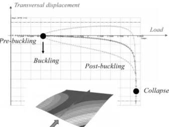
Structural non linear analysis and continuation method Although the stability analysis provides an estimation of the bifurcation points, it is based on a linear approach, and is therefore only an approximation. Moreover, once buckling has occurred, some thin walled structures can sometimes still sustain an increasing loading up to the final collapse [1]. This is illustrated in Figure 1 in the case of a stiffened com-posite panel.
Fig. 1. Illustration of the post-buckling analysis of a stiff-ened composite panel
To simulate the large displacements appearing in a struc-ture beyond its bifurcation point, a geometric non linear analysis is required, in which, contrary to (1), the stiffness matrix changes all over the loading. A non linear system of equilibrium equations (3) is therefore solved, for an imposed load factor λ or displacements q. When a limit point (e.g. collapse) must be identified, the classical Newton-Raphson method can present problems, and a continuation method (also called arc length or Riks method) must be used. In this method, q and λ are unknown and linked to an additional parameter, called the arc length [13], with equation (4). This parameter is controlled over the iterations. The complete set of equations can now be now written as:
0 ) , (qλ = F (3) 0 ) , (q λ = c (4)
The Reserve Factor associated with the collapse load is given by the load increment λ, i.e. RF = λcollapse. At the solu-tion, RF must be larger than or equal to 1, implying that col-lapse will not occur at a loading lower than the nominal one.
Sensitivity analysis of the collapse load
The goal here is to compute the value dλ/dxi, where xi is the ith design variable and λ is the load factor. Starting from the equilibrium equations and knowing that the forces de-pend on the displacement q, the load increment λ and the set of design variables x, it follows that
0 = ∂ ∂ + ∂ ∂ + ∂ ∂ λ λd d d x F x F q q F (5) The unknown vector is also constrained to be orthogonal to the load-displacement curve rather than being a simple measure based on the vertical gap ∆λ. This allows a better accuracy of the sensitivity measure. It turns out that dλ/dx can be computed from the tangent stiffness matrix; the varia-tion of the internal forces with respect to the design vari-ables is computed by finite differences. Details are given in [10,14].
2.3 Advanced damage tolerance analysis
When the fracture mechanics approach is applied to the delamination of laminated composites [2,6], the finite ele-ment method is used to model the cracked structure and to compute the energy release rates GI, GII and GIII, related to
each of the three modes (I, II and III) of inter-laminar frac-ture (crack lips opening, sliding shear and tearing, respec-tively). Once these values are computed at each node defin-ing the crack front, they are inserted in a criterion such as (5) and compared to GIC, GIIC and GIIIC, which characterize the
inter-laminar fracture toughness in the three individual modes. 1 < + + IIIC III IIC II IC I G G G G G G (5) When the value in (5) reaches unity, it is assumed that the crack will propagate in the structure. In this paper a specific Virtual Crack Extension method is used to compute GI, GII
and GIII. This computation is carried out in a linear analysis.
The method is decomposed into two steps. In the first, the variation of the total potential energy π at equilibrium is evaluated: III II I T G G G dA d G =− π = + + (6)
Considering the expression of π in linear elasticity, and taking the derivative with respect to the crack length (sur-face) A, it turns out that:
q g Kq qT − T = 2 1 π
=>
dA d dA d dA d g q q K qT − T = 2 1 πwhere q are the nodal displacements and g is the vector of applied nodal forces. In a semi-analytical approach, dK/dA can be replaced by ∆K/∆A. The total energy release rate GT in (6) is finally obtained from (7), where the index
init corresponds to the initial (actual) crack length, and pert denotes a perturbed configuration of the crack associated with a virtual (very small) advance in its local plane. Equa-tions (6) and (7) clearly show how the sensitivity analysis
International Journal for Simulation and Multidisciplinary Design Optimization for structural optimization and the calculation of the energy
release rate in a fracture mechanics problem are related.
A dA d GT pert init ∆ − − ≅ − = π (π π ) (7)
In the second step, the total energy release rate given by (7) is distributed over the three modes GI, GII and GIII,
con-sidering the relative displacements of the lips and the reac-tions to the crack opening, sliding and tearing at the crack front. The VCE method is used in SAMCEF to identify the most critical cracks in a structure, and to estimate the propa-gation load, i.e. the amplitude of the load leading to at least one crack propagation, according to criteria such as (5). This method is illustrated in Figure 2, for mode I.
Fig. 2. Principle of the VCE method illustrated on a Double Cantilever Beam (DCB)
A semi-analytical sensitivity analysis of the energy re-lease rate with respect to ply thickness and fibres orientation has not yet been developed in SAMCEF, but is somehow related to the structural stiffness. Moreover, as explained in Section 4, some uncertainties still exist concerning the for-mulation of the optimization problem.
2.4 Pre-design criteria for composite aircraft structures
Structural analysis
A wing is divided into a set of super-stiffeners, made of a portion of the skin and a T-stiffener (Figure 3). The Reserve Factors are computed at the local level, i.e. in each super-stiffener. According to [3,11,15], several criteria can appear in the formulation of the pre-design of a composite aircraft wing. In this case, Reserve Factors reflect buckling, damage tolerance, reparability and some design rules at the super-stiffener level. The values of these RFs vary with respect to design variables, which are the panel thickness, the propor-tions of fibres oriented at 0°, ±45° and 90°, and dimensions of the stiffeners (web and flange height, web thickness, etc). The RFs are also functions of internal forces, N, computed from a global finite element model of the wing as depicted in Figure 3. The RFs values at the local level (in the super-stiffeners) are calculated using analytical formulas.
Fig. 3. The bottom surface of a wing and its associated su-per-stiffeners where local computations are carried out
Sensitivity analysis
The interaction between the local and the global effects is taken into account by the sensitivity analysis, as illustrated in Figure 3, through the modification of the internal forces N with respect to a change in each design variable x. While the computation of global sensitivities are based on semi-analytical derivatives, finite differences and massive paral-lelism are used for computing the derivatives of the local values, on the set of super-stiffeners. For details, see [8,11].
3 Basic description of the optimization
methods
Several optimization methods are used in this paper, depend-ing on the application. The selection of an efficient optimi-zation method depends on the problem to be solved. When derivatives are available and when the problem includes a large number of design variables and design functions, it is recommended to use a gradient-based method, such as a Sequential Convex Programming method (SCP). On the other hand, when derivatives are not available, either be-cause the problem is non differentiable, or simply bebe-cause they have not be implemented, the use of a Genetic Algo-rithm (GA) is certainly a good choice, assuming that the computational time for a structural analysis is very low and that the problem includes few design variables. When non linear structural analyses are conducted, a Surrogate Based Optimization method (SBO) is preferred to a Genetic Algo-rithm. In this case the number of design variables must how-ever remain relatively small. To conclude therefore, it is important to note that a gradient based optimization method will not generally provide the global optimum of the prob-lem, while a Genetic Algorithm will, for a large population. Moreover, when working with discrete design variables, GA is a natural and easy choice. In the following applications, continuous design variables are considered, and SCP and SBO methods are used.
3.1 The general optimization problem
The optimization problem to be solved takes the following form: ) OB( F x min 1 ) ( F R j x ≥ j=1,...,m (8) i i i x x x ≤ ≤
i=1,...,n
where x is the set of design variables, FOB is the objec-tive function (weight or total energy release rate in the fol-lowing applications), and RFj is the j
th
Reserve Factor. Two methods are used in what follows. For a detailed presenta-tion of optimizapresenta-tion methods, the reader should refer to [7,8].
3.2 Sequential Convex Programming - SCP
In this gradient-based approach, the solution of the initial optimization problem (8) is replaced by the solution of suc-cessive explicit approximations, as illustrated in Figure 4 for an unconstrained optimisation problem. A generalization of the MMA approximation, developed in [7] and available in the BOSS Quattro optimization toolbox, is used. This method automatically generates monotonous or non mo-notonous approximations of the structural response with respect to the design variables, in order to have an accurate model of the initial optimization problem. An approximation of problem (8) is generated based on the functions value and their first order derivatives (obtained from structural and sensitivity analyses, respectively). Once the solution of an approximated problem is obtained, it is checked to see whether convergence has been reached. If this is not the case, a new approximation is built, and the process is con-tinued until convergence to a desired accuracy is achieved. The advantage of this method is that it requires a small number of iterations to reach the solution (say between 10 and 25) irrespective of the number of design variables. However, derivatives must be available, and generally only local optima can be identified. For constrained optimisation problem, a dual approach is used (see [7]).
Fig. 4. Illustration of the Sequential Convex Programming approach
3.3 Surrogate Based optimization - SBO
In this method [8], only the function values are used to build a global approximation of the design domain, as illustrated in Figure 5. A response surface is generated based on a Neu-ral Network (NN) or a Radial Basis Function (RBF). The optimum of this global approximation is obtained with a genetic algorithm. The new point is then used to build a new response surface, and the process is repeated until conver-gence. The advantage of this approach lies in the fact that it can be used when the derivatives are not available. On the other hand, it results in a prohibitively long computational time when a large number of design variables is used. How-ever, parallelism allows a reduction – to some extent – of the time needed to find a solution. For constrained optimisation problems, a penalty is used.
Fig. 5. Illustration of the Surrogate Based Optimization approach
4 case study 1: design with respect to
de-lamination
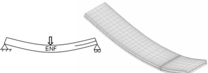
Designing a composite structure with respect to damage tolerance is becoming a challenge. Although simplified for-mulations may be used at a global level for a pre-design (e.g. a complete wing [11]), more sophisticated high fidelity ap-proaches should be selected when local detailed structural components are studied. An ENF (End Notched Flexure) specimen is considered here (Figure 6). The function to be minimized is the total energy release rate GT (6) over the
crack front, in order to design a laminate less sensitive to delamination. Since the value of GT varies along the crack
front, minimum, mean and maximum values are therefore minimized, in order to obtain a laminate less prone to crack propagation. Only one design variable is selected: it is the angle of the following lay-up: [±θ /0/- θ /0/ θ /04/ θ /0/- θ
/0/- θ / θ /d/- θ / θ /0/ θ /0/- θ /04/- θ /0/ θ /0/± θ]. The initial
value of θ is 30°.
The inter-laminar toughnesses GIC, GIIC and GIIIC used in
the criterion (5) depend on the fibre orientations across the interface [16]. Moreover, a large dispersion in the inter-laminar toughness values exists. In the simplified approach adopted here, a constant value of GC is considered. For the sake of accuracy this variation of GC should be included in the formulation of the optimization problem, and robust op-timization methods should be used [17]. The current ap-proach is therefore not rigorous and aims rather at comparing optimization methods. The results must therefore be inter-preted with care.
Fig. 6. The ENF test case, and its finite element model
First the SCP method presented in [7] is used, and the sensitivities are up-to-now computed by finite differences. The results of the iterative optimization process are presented in Figure 7a. The optimal value of θ (0-deg) is obtained after 8 iterations, and 15 structural analyses.
International Journal for Simulation and Multidisciplinary Design Optimization
Fig. 7. The ENF test case, on its finite element model
Surrogate Based Optimization methods [8] – where Neu-ral Networks or other response surfacesare used to generate a global approximation of the design problem – may be effi-cient for treating the damage tolerance problem, as was the case in [1] for post-buckling optimization of composite structures. In this case, their main advantage is that analyses are run on parallel processors, which is not possible with a sequential gradient-based approach such as SCP. Applying such a method to the problem depicted in Figure 6 provides the solution after 63 structural analyses, which is competi-tive with the SCP method since 4 processors were used for the parallel solution (Figure 7b). The formulation of this kind of problems should be further investigated.
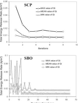
5 case study 2: design of a stiffened panel
A hat-stiffened curved composite panel subjected to shear and compression is considered (Figure 8).Fig. 8. Curved composite panel and its super-stiffeners In each super-stiffener (Figure 8b), three design variables are related to the thickness of the plies oriented at 0°, ±45° and 90° to the skin, and three other design variables are
de-fined for the corresponding values in the stiffener. Since seven panels are used to form the structure, 42 design vari-ables are defined in the problem.
5.1 Optimization with respect to buckling
The goal is to find the values of the ply thickness that mini-mize the weight while satisfying RF ≥ 1, according to (1). It can be seen in Figure 9 that when only the first 12 load fac-tors are considered in the design problem, large oscillations appear. Given the local character of the associated buckling modes, some structural parts may become insensitive to buckling, and the modes start to move all over the structure during the iterative optimization process, leading to oscilla-tions. In contrast, when a large number of buckling loads are taken into account, the whole structure remains sensitive to buckling and, insofar as a reliable optimization method is used, the solution can be obtained in a small number of iterations (Figure 9). More details can be found in [9].
Fig. 9. Convergence history for 12 and 100 buckling modes
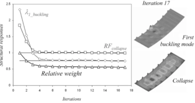
5.2 Optimization with respect to buckling and col-lapse
This problem can be solved when post-buckling behaviour is considered as well. In this case, post-buckling is allowed to develop in the structure, and the buckling loads are pre-scribed to be larger than 0.76. The collapse must appear for λcollapse ≥ 1. The results are presented in Figure 10, where 100
buckling modes are taken into account. The solution is ob-tained after 17 iterations. As in the previous section, conver-gence problems (oscillations) are observed when a small number of buckling modes is used.
Fig. 10. Convergence history for buckling and collapse opti-mization
6 case study 3: large scale optimization of
a composite aircraft component
Only a part of the composite box structure of a wing is con-sidered in this optimization problem. Based on Section 2.4, the mass is to be minimized, while 71552 restrictions on buckling, damage tolerance and reparability are defined on the several super-stiffeners composing the wing box. The problem includes 630 design variables (panel thickness, and size of the stiffeners). As illustrated in Figure 11, the solu-tion is found after 10 iterasolu-tions. More details on a full wing optimization are available in [9,11].
Fig. 11. Convergence history for the optimization of the composite wing
7 Conclusions
The use of advanced structural analyses and optimization methods has become challenging in the design of composite structures. This paper presented three main kinds of recent applications. Depending on the problem, either a gradient based or a surrogate-based optimization method can be used. This comparison should be further investigated, especially when local non linear analyses, such as delamination, post-buckling and collapse, are considered. Indeed, in such cases, few design variables are used, and both methods could be-come competitive.
Acknowledgement
The support of the European Commission (VIVACE Project) and of the Walloon Region of Belgium (OPTISTACK Pro-ject) is gratefully acknowledged.
References
1. L. Lanzi, V. Giavotto, Post-buckling optimization of composite stiffened panels: computations and experi-ments, Compos. Struct. 73, 208-230 (2006).
2. R. Krueger, Computational fracture mechanics for com-posites – State of the art and challenges, In NAFEMS Seminar – Prediction and Modelling of Failure Using FEA (2006).
3. F. Huttner, M. Grosspietsch, Solving very large scale structural optimization problems, AIAA J 45(11), 2729-2736 (2007).
4 SAMCEF. Système d’Analyse des Milieux Continus par Eléments Finis. www.samcef.com
5. Y. Radovcic, A. Remouchamps, BOSS quattro: an open system for parametric design, Struct. Multidiscipl. Op-tim. 23, 140-152 (2002).
6. M. Bruyneel, J.P. Delsemme, F. Germain, Ph. Jetteur, A study of complex delaminations in laminated composite structures with SAMCEF, In Fourth International Con-ference on Advanced Computational Methods in Engi-neering (2008).
7. M. Bruyneel A general and effective approach for the optimal design of fibers reinforced composite structures, Compos. Sci. Technol. 66, 1303-1314 (2006).
8. A. Remouchamps, S. Grihon, B. Colson, C. Raick, M. Bruyneel, Numerical optimization: a design space odys-sey, In 1st International Conference on Advancements in Design Optimization of Materials, Structures and Me-chanical Systems (2007).
9. M. Bruyneel, B. Colson, A. Remouchamps. Discussion on some convergence problems in buckling optimiza-tion, Struct. Multidiscipl. Optim. 35, 181-186 (2008). 10. B. Colson, M. Bruyneel, Ph. Jetteur, P. Morelle, A.
Re-mouchamps, Composite panel optimization with non linear finite element analysis and semi-analytical sensi-tivities, In NAFEMS Seminar – Simulating Composite Materials and Structures (2007).
11. L. Krog., M. Bruyneel, A. Remouchamps, C. Fleury, COMBOX: a distributed computing process for opti-mum pre-sizing of composite aircraft box structures, In 10th SAMTECH Users Conference (2007).
12. H. Adelman, R.T. Haftka, A discourse on sensitivity analysis for discretely-modelled structures, NASA Technical Memorandum 104065.
13. E. Riks, C. Rankin, F. Brogan, On the solution of mode jumping phenomena in thin walled shell structures, Comp. Meth. Appl. Mech. Engng. 136, 59-92 (1996). 14. M. Bruyneel, B. Coslon, J.P. Delsemme., Ph. Jetteur, A.
Remouchamps, S. Grihon, Exploiting semi-analytical sensitivities from linear and non-linear finite element analyses for composite panel optimization, to appear in Int. J. Struct. Stability & Dynamics (2009).
15. D. Weiss, Optimization in aircraft pre-design with siz-ing criteria, Diploma Thesis N° IMES-ST 06-019, Swiss Federal Institute of Technology Zurich (2006). 16. O. Allix, D. Lévêque, L. Perret, Identification and
fore-cast of delamination in composite laminates by an inter-laminar interface model, Compos. Sci. Technol., 58, 671-678 (1998).
17. H.G. Beyer, B. Sendhoff, Robust Optimization – A Comprehensive Survey, Comput0 Meth. Appl. Mech. Engng. 196, 3190-3218 (2007).