Université de Liège
Faculté des Sciences Appliquées
Calculation of internal forces in
axially and rotationally restrained
beams under natural fire
Travail de fin d’études présenté par François HANUS
en vue de l’obtention du diplôme d’Etudes Approfondies en Sciences Appliquées
2
Acknowledgements
Professor J. M. Franssen, promoter of this
work, is gratefully acknowledged for having
supervised this work and for his helpful advices.
I am also grateful to my colleagues who, by
the way of scientific discussions and an unfailing
friendship, help me everyday to overcome new
obstacles.
Finally, I would like to thank my family and
best friends for their indispensable support
François Hanus
3 Faculté des Sciences Appliquées 3ème cycle Année académique 2007-2008
” Determination of internal forces in axially and rotationally restrained
beams submitted to a natural fire “
When a constituent of a frame is subjected to fire, the thermal dilatation and bowing of this element is limited by the action of the surrounding frame. The reduction of steel mechanical properties and restrained thermal deformations induce a new distribution of internal forces in the frame. Generally, the stability of structures is calculated by the use of recommended temperature-time curves that do not considered the cooling phase of the fire. After being submitted to high compressive forces and experiencing significant plastic deformations, heated elements become in tension. As it was observed experimentally, the failure of bolts due to an excess of tensile forces may occur during the cooling phase of the fire.
That is the reason why a research project on the design of connections subjected to natural fire (COSSFIRE) has been funded by the Research Fund for Coal and Steel (RFCS). The objective of this project is to provide experimental data and to propose guidelines for designing the joints including both the heating and cooling phases.
This work describes a part of the contribution of the University of Liège in the project COSSFIRE. It is focused on the determination of the internal forces experienced by axially and rotationally restrained beams submitted to a natural fire. This preliminary step is essential for an optimised design of connections in similar conditions.
This work is subdivided three parts. Firstly, some experimental tests have been modelled numerically with the homemade finite element software SAFIR in order to validate it and the models used to analyse this type of problem. Secondly, a set of parametrical analyses have been performed in order to better understand the influence of several factors on the induced internal forces and provide some reference results for the last part of the work. Finally, some simplified methods, based on Wang’s method, have been defined to allow determining the internal forces in a given case without requiring any numerical simulation in finite element packages.
Promoteur : J. M. Franssen Membres du jury :
4
1 Introduction
1.1 Context
For about fifty years, scientists and engineers have been focussing on the structural behaviour of buildings submitted to fire and have been investigating on improvements that enable to fulfil demands aiming at insuring the humans’ safety and reducing material damages. These purposes can only be accomplished if the stability of constructions is guaranteed during a sufficient period of time in order to make possible the evacuation of persons and the intervention of firemen. The expansion of fire to other parts of the devastated building has also to be avoided.
Steel constructions lose rather quickly their stability when submitted to elevated temperatures. The main explanations to this are the relative thinness of individual elements and the high conductibility of steel. The fast heating of structural elements induces an important reduction of their mechanical properties. Consequently, it is often necessary to protect steel structures thermally with sheets of insulating materials or intumescent paintings.
The evolution of the mechanical behaviour of beams and columns at elevated temperatures is quite widely known. However, the joints behaviour under fire loading has not been studied so extensively.
In the first European design codes, it was considered as unnecessary to focus on the behaviour of joints under fire conditions because of the less severe exposition to fire and the presence of more material in the joint zone. The large amount of joints typologies, the large number of parameters influencing their behaviour and the difficulty to realize some tests are other explanations to the lack of sufficient knowledge of joints behaviour under fire conditions.
As the response of joints is very important in global frames analyses, some investigations were conducted during the last few years, mainly in Europe. The first design rules have been stated from the Component Method developed initially for joints at room temperature. This method has been adapted later to accommodate with the design of joints under fire loading. More recently, some real-scale tests performed in Cardington and Vernon have shown that the failure of steel or steel-concrete composite structures may occur in connection components during the cooling phase due to the tensile forces created in steel beams after significant plastic deformations have been undergone during the heating phase.
5 A research project, supported by the Research Fund for Coal and Steel (RFCS), is aiming at enhancing the scientific findings and to develop efficient, practical and economic design rules on steel connections when exposed to real fire conditions as a result of experimental, numerical and analytical investigations. The present work reports a part of the numerical and analytical developments carried out at the University of Liège as a partner of this research project still in progress. The objectives and the content of this study are briefly described in the following paragraph.
1.2 Objectives
The failure of steel and steel-concrete composite structures may happen during the cooling phase of a natural fire owing to the incapacity of joints to resist applied tensile forces. The evaluation of the axial load applied to joints depends on a range of parameters: fire loading, mechanical loading, axial and rotational restraints provided by the surrounding structure, beam stiffness and resistance. The main objective of this work consists in analysing the structural behaviour of steel and composite structures and quantifying the axial thrusts created during both the heating and cooling phases in function of the above-mentioned parameters. The work is divided in the following steps:
Chapter 2 is a large overview of the available knowledge in the behaviour and the design of connections at room and elevated temperature. The classification of joints and the design method proposed in the recent European standards are reported. The experimental and analytical works undertaken in the scope of determining internal forces in restrained elements are shortly described.
Chapter 3 is a more detailed description of experimental tests that have been simulated numerically in order to validate the homemade software SAFIR and the type of model used later in the parametrical analysis.
SAFIR and CoP programs are presented in Chapter 4. A special attention is given to the new material laws defined in SAFIR in order to improve the modelling of the behaviour of connections in structural analyses.
In Chapter 5, numerical analyses of experimental tests performed in SAFIR program are presented.
Chapter 6 is dedicated to the description of the parametrical analyses. One-dimensional and two-dimensional are successively considered. In both cases, reference cases are chosen and
6 analysed accurately and then, the influence of several parameters is studied.
Chapter 7, based on the Wang’s method and the results provided by the parametrical analyses, consists in the definition of a simplified method to calculate the internal forces and evaluate the displacements of a restrained beam submitted to natural fire. Some improvements to the Wang’s method and an extension to cooling phase are proposed.
Conclusions and output of the present work are presented in Chapter 8. Perspectives for future studies are also listed in this section.
7
2 State-of-the-art
2.1 Introduction
The present paragraph aims at producing a state-of-the-art about the fire safety engineering and natural fire concept, the design and the behaviour of steel and composite steel-concrete connections at room temperature and elevated temperatures and the evaluation of internal forces in restrained elements submitted to fire.
2.2 Fire Safety Engineering and Natural Fire Concept
The overall purpose of fire safety is to reduce the risk of life and property losses, the main concern being the safety of lives. Fire Safety Engineering is a global discipline aiming at determining safety strategy for buildings submitted to fire conditions, in which structural stability and control of fire spread are achieved by providing adequate active and/or passive fire protection.
Structural Fire Engineering is the part of that discipline dealing with the thermo-mechanical analyses of structures submitted to fire and the design of members that ensures a sufficient load bearing resistance and controls the fire spread. A fire analysis consists of four successive steps:
Selection of the design fire scenarios Modelling of the fire
Thermal Analysis Structural analysis
The starting point of a fire is the presence of three elements simultaneously: oxygen, fuel and a heat source. The evolution of temperature during a real fire can be divided in five phases:
i. Smouldering phase: ignition and smouldering fire at very low temperature (not considered in calculations and tests) ;
8 iii. Flashover: formation of a generalised fire (very short period of time) ;
iv. Post-flashover: combustion of the combustible materials (variable duration) ; v. Decreasing phase: combustible materials have completely burnt and temperature
decreases.
The duration of the post-flashover phase depends on the fire loading (total energy released by the complete combustion of materials situated in the compartment divided by the floor area), the surface of openings and the characteristics of walls.
Many experimental and theoretical investigations undertaken more than 25 years ago have lead to the definition of a unique ISO standard temperature-time curve:
T – Tini = 345 log10 (8 t + 1)
o t is expressed in minutes ;
o Tini is the initial temperature in the room or the furnace ; o T is the ambient temperature.
This ISO-834 curve is considered as quite severe for fires in buildings and is one of the numerous standard temperature-time curves (ASTM-E.119 [ASTM, 1998], JIS A 1304 [JIS, 1982]). However, these curves do not describe natural fires realistically. A more rational approach to fire engineering design of buildings requires methods based on actual fire exposure conditions. By example, Annex A of EN 1991-1-2 [CEN, 2002] proposes some parametrical temperature-time curves.
2.3 Thermal analysis of steel elements
2.3.1 Steel thermal properties at elevated temperatures
The specific heat c is the measure of the heat energy required to increase the temperature of a material during a certain temperature interval.
9
Figure 2-1 : Specific heat of carbon steel as a function of temperature (EN 1993-1-2)
The thermal conductivity λ of a material characterizes its ability to conduct heat. It is defined as the quantity of heat transmitted during a period of time per unit of length.
Figure 2-2 : Thermal conductivity of carbon steel as a function of temperature (EN 1993-1-2)
The emissivity of a given material is the ratio between the radiative heat absorbed by a surface made of this material and that of a black body surface. In general, the emissivity of structural materials may be taken as equal to 0.8 according to EN 1991-1-2 [CEN, 2002] recommendations but the EN 1993-1-2 [CEN, 2005] allows to consider a value equal to 0.8.
The relative thermal elongation is the ratio between the variation of length ΔL undergone by a steel element owing to thermal variation and the length L of the element at room temperature. This parameter is approximately linear until 750°C, remains constant in the range [750°C ; 860°C] and increases linearly after this plateau (Figure 2-3).
10
Figure 2-3 : Relative thermal elongation of carbon steel as a function of temperature
2.4 Joints calculation at room temperature
2.4.1 Definitions
The two different English words “joints” and “connections” are distinguished in the Eurocode 3-1-8 [CEN, 2003]. A connection is a location where two or more elements meet. The most common types of connections are double angle web cleats connections, flange cleats connections, flush and extended end plate connections, fin plate connections and welded connections. For design purposes, the connection is the assembly of the basic components required to represent the behaviour during the transfer of the relevant internal forces and moment at the connection. The joint is the zone where the members are interconnected (Figure 2-4). The most common joint configurations are single-sided and double-sided beam-to-column joints, beam and columns splices and column bases (Figure 2-5). For design purposes, the joint is the assembly of all the basic components required to represent the behaviour during the transfer of the relevant internal forces and moments between the connected members. For example, a beam-to-column joint consists of a web panel and one connection or two connections.
11
Figure 2-4 : Parts of a beam-to-column configuration
Figure 2-5 : Joint configurations 2.4.2 Classification of joints
Joints may be classified by their stiffness and by their strength.
2.4.2.1 Classification of joints by stiffness
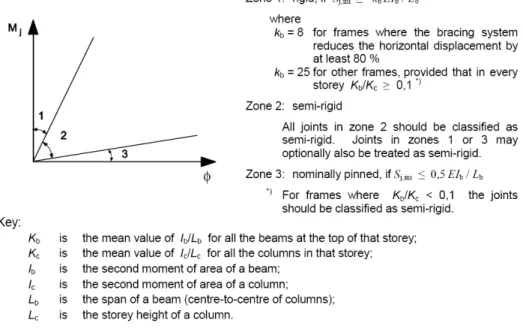
A joint may be classified as rigid, nominally pinned or semi-rigid according to its rotational stiffness by comparing its initial rotational stiffness Sj,ini with the classification boundaries defined in Figure 2-6. The rotational stiffness of a joint is the moment required to produce a unit rotation in that joint.
12
Figure 2-6 : Classification of joints by stiffness according to prEN 1993-1-8 : 2003
2 3 6 5 4 7 1 Rigid Semi-rigid Flexible Φ
M 2 Extended end plate 1 Fully welded 3 Top and bottom flange splices
4 Flush end plate 5 Flange cleats and web angles
6 Flange cleats 7 Double web angle
Figure 2-7 : Typical beam-to-column joints and a diagrammatic stiffness classification (S. Spyrou, 2002)
A nominally pinned joint shall be capable of transmitting the internal forces, without developing significant moments which might adversely affect the members or the structure as
13 a whole and shall be capable of accepting the resulting rotations under the design loads. Joints classified as rigid may be assumed to have sufficient rotational stiffness to justify analysis based on full continuity. A joint which does not meet the criteria for a rigid joint or a nominally pinned joint should be classified as a semi-rigid joint. It should be capable of transmitting the internal forces and moments.
2.4.2.2 Classification of joints by strength
A joint may be classified as full-strength, nominally pinned or partial strength by comparing its design moment resistance Mj,Rd with the design moment resistances of the members that it connects. When classifying joints, the design resistance of a member should be taken as that member adjacent to the joint.
The design resistance of a full-strength joint shall not be less than that of the connected members. A joint may be classified as full-strength if it meets the criteria given in Figure 2-8. A nominally pinned joint shall be capable of transmitting the internal forces, without developing significant moments which might adversely affect the members or the structure as a whole. It shall be classified as nominally pinned if its design moment resistance Mj,Rd is not greater than 0,25 times the design moment resistance required for a full-strength joint, provided that it also has sufficient rotation capacity to accept the resulting rotations under the design loads. A joint which does not meet the criteria for a full-strength joint or a nominally pinned joint should be classified as a partial-strength joint.
Figure 2-8 : Criteria for full-strength joints M Φ Full-Strength Partial-Strength Pinned Mp 0.25Mp
14
2.4.3 Global analysis
To identify whether the effects of joint behaviour on the analysis need to be taken into account, a distinction may be made between three simplified models as follows:
- simple, in which the joint may be assumed not to transmit bending moments;
- continuous, in which the behaviour of the joint may be assumed to have no effects on the analysis;
- semi-continuous, in which the behaviour of the joint needs to be taken into account in the analysis.
Table 2-1 : Types of joint models
2.4.3.1 Elastic global analysis
In an elastic global analysis, the joints are classified according to their rotational stiffness and shall have sufficient strength to transmit the forces and moments acting at the joints resulting from the analysis.
In the case of a semi-rigid joint, the rotational stiffness Sj corresponding to the bending moment Mj,Ed should generally be used in the analysis. If Mj,Ed does not exceed 2/3 Mj,Ed, the initial rotational stiffness Sj,ini may be taken in the global analysis (Figure 2-10a). As a simplification to this, the rotational stiffness may be taken as Sj,ini/η in the analysis, for all values of the moment Mj,Ed (Figure 2-10b) where η is the stiffness modification coefficient shown in Table 2-2.
15
Figure 2-10 : Rotational stiffness to be used in elastic global analysis according to prEN 1993-1-8:2003
Table 2-2 : Stiffness modification coefficient η
2.4.3.2 Rigid-plastic global analysis
In a rigid-plastic analysis, the joints should be classified according to their strength and the rotation capacity of a joint shall be sufficient to accommodate the rotations resulting from the analysis.
2.4.3.3 Elastic-plastic global analysis
The joints should be classified according to both stiffness and strength. The moment-rotation characteristic of the joints should be used to determine the distribution of internal forces and moments. As a simplification, the bi-linear design moment-rotation characteristic shown in Figure 2-10 may be adopted, where η is the stiffness modification coefficient.
2.4.4 Component method
The Component Method is a versatile approach for calculating rotational stiffness, axial stiffness and the capacity of joints. The original feature of this method is to consider any joint as a set of individual basic spring-like components (Figure 2-11). For each component, the non-linear stiffness and maximum force is computed and assembled to form a spring model,
16 which represent the global behaviour of the joint.
Figure 2-11 : Spring model of an extended end-plate joint for moment and axial force (Cerfontaine, 2004)
The application of this method requires the following three steps:
- Identification of the active components in the considered joint;
- Evaluation of the stiffness and/or resistance characteristics for each individual basic component;
- Assembly of all components and evaluation of the whole joint stiffness and/or resistance characteristic.
2.4.5 Analytical characterisation of joints under bending moment
As shown on Figure 2-7, the actual moment-rotation response of a joint is usually non-linear. Based on the Eurocode prEN 1993-1-8 recommendations [CEN, 2003], COST C1 [J.-P. Jaspart, 1994] suggests three different M-φ relationships to characterize the semi-rigid behaviour of connection at room temperature.
17
φ Cd φ Cd
Sj,ini Sj,ini
Sj,ini/η
BI-LINEAR TRI-LINEAR NON-LINEAR
MRd
MRd
MRd
φ Cd : Real Joint Behaviour
: Idealized Joint Behaviour
In the bi-linear law, the stiffness of the joint Sj is assumed to remain constant until the applied bending moment Mj,Ed is equal to the resisting bending moment Mj,Rd. In beam-to-column connections, Sj =Sj,ini/2 ;
In the tri-linear law, the stiffness of the joint is equal to the initial stiffness Sj,ini until Mj,Ed = 2/3 Mj,Rd. For Mj,Ed ∈ [2/3 Mj,Rd ; Mj,Rd], Sj =Sj,ini/7 ;
In the non-linear law, the stiffness of the joint is equal to the initial stiffness Sj,ini until Mj,Ed = 2/3 Mj,Rd. A non-linear function of the stiffness is defined for Mj,Ed ∈ [2/3 Mj,Rd ; Mj,Rd] :
(
1,5 , , ,)
j ini j j Ed j Rd S S M M ψ= whereΨ =2,7 in end-plate and welded connections.
Considering one of these elastic-plastic curves, it is necessary to check if the joint rotation does not exceed its rotation capacity φCd. Eurocode 3 does not mention any calculation method to evaluate the rotation capacity. Jaspart has proposed a method to evaluate a post-critical stiffness of a joint and to deduce the rotation reached at the ultimate bending moment [Jaspart, 1991].
2.5 Joints calculation at elevated temperature
The summarization of the previous researches and experimental programmes carried out in the field of connections under fire loading is partially based on an article of Al-Jabri published recently [K.S. Al-Jabri and al., 2008]. The design of connections under natural fire necessitates the assessment of internal forces in the joint taking into account the evolution of stiffness during the fire and the verification that the resistance of the joint is sufficient. The evaluation of axial thrusts created by fire in restrained elements during both heating and
18 cooling phase still needs to be investigated experimentally because few results are currently available. However, several numerical tools predict quite accurately the internal forces produced by fire.
2.5.1 Mechanical behaviour of joints submitted to fire
The first experimental tests on connections under standard fire conditions have been undertaken at CTICM [J. Kruppa, 1976]. This study was not focused on the global behaviour of joints but it showed that the failure of bolts was preceded by important deformations in the other elements. A couple of years later, INSA of Rennes performed some tests on bolts at elevated temperatures to investigate on their behaviour both under tension and shear loading [H. Riaux, 1980]. The creep influence was particularly analysed.
British Steel conducted two fire tests on rigid joints [British Steel, 1982]. These results showed that significant deformations are undergone in the joint during the fire and that the assumption of a rigid behaviour at high temperatures is consequently not valid.
The first tests realized to investigate on the global behaviour of joints have been performed by Lawson on three common types of connections: extended end-plate, flush end-plate and double web-cleats connections [Lawson and al., 1990]. Both bare-steel and steel-concrete composite connections were studied. Lawson observed that significant bending moments are transferred during the fire test. He suggested that composite action in fire contributes to an enhanced moment capacity of joints, which could be estimated by adding the moment capacities of the bare steel joint and the reinforced concrete slab In addition, he proposed a simple method to design simply supported beams submitted to fire and adapted it in order to integrate the effect of moments transferred by joints.
Leston-Jones tests [L. C. Leston-Jones, 1997] was aimed at deriving a set of moment-rotation curves of a unique joint configuration (flush end-plate connections) submitted to five different load ratios at elevated temperature. A modified form of the Ramberg-Osgood equation has been used to define some simplified connection models, based on mathematical curve-fittings procedures. Some numerical simulations made with a software integrating these moment-rotations curves have shown that the fire performance of sub-structures may be significantly enhanced when the real behaviour of common connections, usually considered as pinned, is integrated.
Kirby investigated widely on the behaviour of high-strength 8.8 bolts in fire. He realized series of tests in tension and double shear at temperatures up to 800°C [B.R. Kirby, 1995]. Tests in tensions have highlighted the possible premature failure by thread stripping. The comparison between the performances of high-strength bolts with Eurocodes recommendations for hot rolled structural steel showed that the bolts are far more sensitive
19 due to the heat treatment methods used in their manufacture. A strength reduction factor was defined for bolts acting in shear and tension.
Al-Jabri conducted series of anisothermal tests to analyse the influence of several parameters on the behaviour of typical joint typologies [K.S. Al-Jabri and al, 1998]: the test series included two full end-plate and one flexible end-plate bare steel connections, and two flexible end-plate composite connections. Moment-rotation temperature curves were derived for each type of connection [K.S. Al-Jabri and al, 2005].
In 2001, an adaptation of the Component Method was proposed in order to extend its applicability to steel joints submitted to fire loading [L. Simões da Silva and al., 2001]. The resistance and the stiffness of each component are multiplied by reduction factors and isothermal moment-rotation diagrams can be obtained at any temperature. That method showed a good agreement with experimental tests already available in literature. A procedure for the evaluation of ductility in steel joints has also been presented [L. Simões da Silva and al., 2002] for end-plate connections.
Spyrou investigated successively on the tension zone and compression zone component within a steel joint at elevated temperature [Spyrou, 2002]. Based on the work previously done by Jaspart [J.P. Jaspart, 1994] at room temperature on T-stubs, he proposed a simplified method to calculate the three failure modes in tension. Concerning the compression zone, Spyrou developed a new method less conservative than those given in BS5950 [BSI, 2000] and ENV 1993: Annex J [CEN, 1994]. The work accomplished on the compression zone was continued by Block: experimental tests at elevated temperatures lead to an improvement of the analytical model [F.M. Block and al., 2005].
2.5.2 Internal forces in restrained elements
The performance of isolated elements in fire is strongly dependent on the boundary conditions. Axial and rotational restraints induce stresses when thermal elongation and thermal bowing are prevented. However, some experiments have shown that the presence of restraints enhance the fire resistance of steel beams. In a study on extended and flush end-plate connections, Liu has shown that the enhancement of the load capacity of an unprotected beam at fire limit state may reach two-thirds of the moment capacity of the beam [T.C.H. Liu, 1999].
In a structure exposed to a real fire, heated elements are successively loaded in compression during the whole heating phase, unloaded during the first part of the cooling phase and loaded in tension until a uniform temperature of 20°C in the structural elements. The first researches were mainly concentrated on the heating phase. Liu conducted an experimental programme, consisting of 16 fire tests on flush end-plate and web-cleat connections, to study the large
20 deflection behaviour of restrained beams [T.C.H. Liu and al.]. It confirmed that connections can enhance the fire resistance of a beam by reducing some of the mid-span moment during most of the time when temperature is rising, despite the possibility of local buckling in the beam. In web-cleat connections, the transfer of moment is low but a noticeable advantage may be derived from the effect of catenary action.
Wang proposed a simple method to analyse catenary action in steel beams submitted to elevated temperatures [Y.C. Wang and al., 2005a and 2005b]. This method necessitates making an assumption on the beam deflection profile and consists in satisfying the geometric boundary conditions. Uniform and non-uniform temperature distributions have been considered separately but it has been observed that different non-uniform temperature profiles do not have much effect on beam catenary force.
Some full-scale tests have been realised in Cardington in order to reflect the behaviour of a complete building under fire conditions, taking the interaction between structural members into consideration [L. Simões da Silva, 2006]. These tests have shown that the fire resistance predicted by norms is often underestimated. During the tests, it has been observed that the bolts may fail during the cooling phase.
Some tests, based on the results and observations of Cardington tests, have been realised in Coimbra on restrained sub-structures under natural fire [A. Santiago, 2007]. Six different typologies of joints have been tested. The goal of these tests was to deduce some rules for the design of connections that would avoid collapse of structures.
21
3 Experimental tests
3.1 Tests realized at the University of Manchester
The University of Manchester has carried an experimental programme aimed at examining in detail the role of the connections and axial restraints in the fire resistance of a steel beam when subjected to fire. Twenty fire tests were performed on steel ‘Rugby goalpost’ frames.
Figure 3-1 : Schematics of the test arrangement of Liu [T.C.H. Liu., 1999]
The beams, with a section 178x102x19UB (S275), were mainly unprotected but top flanges were wrapped with 15 mm thick ceramic fibre blanket in order to simulate the heat-sink effect due to the concrete slab. The columns, with a section 152x152x30UC (S275), together with the connections were generally fire-protected by the use of a 50 mm thickness of ceramic fibre blanket.
Two types of connections were selected as being typical of those commonly used in practice, namely double web-cleats and flush end-plates. The web-cleat connection, which is assumed to have no significant moment capacity, was designed for shear only using angle sections 75x75x8 and M16 Grade 8.8 bolts. A 10 mm thick flush-end plate with M16 Grade 8.8 bolts was used as an alternative connection.
22
Figure 3-2 : (a) Flush end-plate connection and (b) Web-cleats connection [T.C.H. Liu., 1999]
The beam specimen was subjected to a constant vertical load and the furnace was programmed to follow the ISO834 standard temperature-time curve [CEN, 2002]. Three main level of loading (load ratios of 0.3, 0.5 and 0.7) were tested. The Load Ratio is defined as the ratio of the applied load under fire conditions to the design load-carrying capacity at room temperature of the beam considered as simply-supported.
The 3 meter 152x152x30UC (S275) fire-protected test column alone provided an axial restraint equivalent to a stiffness of 8 kN/mm to the test beam. The possible in-plane restraint imposed by its neighbouring sub-frames has been estimated by Liu and al. to have a range between 10 and about 70 kN/mm. With the use of additional struts spanning between the column of the test frame and the column of the reaction frame (Figure 3-1), two other overall stiffnesses of 35 and 62 kN/mm were achieved.
In the majority of tests performed on flush end-plate connections, Liu observed formation of plastic hinges in the sections where the loading is applied. An exception is the test FUR17, where the Load Ratio is equal to 0.9 and the axial restraint is 8 kN/mm: the excessive material degradation near the connection probably led to local flange buckling causing an almost immediate failure of the specimen.
In tests with web cleat connections, critical temperatures of the beams are 20°C smaller than those obtained with flush end-plate connections. No local buckling was observed closed near to the extremities of the lower flanges. Although usually considered as pinned, web-cleat connections resisted a minimal amount of moment (around 7 kN.m) and the transferred moment still increased after the 8-mm thick gap between the bottom flange of the beam and the column flange was closed.
23
3.2 Tests realized in the scope of COSSFIRE project
COSSFIRE Project is a European project funded by the Research Fund for Coal and Steel in which the University of Liège is involved. Its main objectives are to enhance the scientific findings and to develop efficient, practical and economic design rules on steel and composite connections when exposed to real fire conditions, including cooling phase. The experimental packages are expected to provide four fire tests on steel structures and four tests on steel and concrete composite structures. In both groups of tests, it was planned to choose one of the three mostly used types of connections (web-cleats, fin-plate and end-plate connections) for a first test under heating up fire exposure condition and a constant applied load to get the critical temperature of this connection. Then, three other fire tests (one with each type of the mostly used connections) are to be carried out under natural fire conditions.
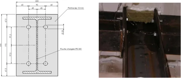
The first two tests have been performed by EFECTIS France. The two used test set-up were identical and are described at (Figure 3-3). The double-sided beam-to-column joint (see blue ring) is composed of two flush end-plate connections whose geometrical characteristics are given in (Figure 3-4). The loaded beam is 5.5 meter-long IPE 300 profile and a portion of 1.7 meter is situated outside the furnace. The HEA 220 column is thermally protected.
The axial restraining system is due to a sub-structure situated outside the furnace and composed of a column and a transversal beam that bends according to its weak axis (Figure 3-3). The mid-span section of the simply-supported transversal beam is connected to the higher extremity of the column that rotates rigidly around its lower pinned support. In order to get an accurate value of the restrained effect, a specific test was carried out. A restrained effect of about 2 kN/mm (1 % of the beam axial stiffness) has been derived.
Figure 3-3 : Schematic representation of the test set-up (left) and view of the restraining sub-structure (right)
24
Figure 3-4 : Geometry of the tested double-sided joint with flush end-plate connections
As these tests are used to investigate on the behaviour of connections including both heating and cooling phases, it is not necessary that the temperature rise of the furnace follows a specific fire curve. It was decided to adopt a temperature rise speed of 10°C/min. During the first test, the specimen was heated increasingly until the steel beam can no longer bear the applied load. For the second test, the specimen was heated up to about 85% of the critical heating obtained with the first test followed by a plateau lasting for about 20 minutes. In both cases, the cooling phase corresponds to the natural cooling condition of the furnace.
25
4 Tools and software
The numerical simulations of tests and parametrical analyses described in chapters 5 & 6 have been realized with the use of SAFIR program. The analytical calculation of the joints according to the Component Method have been realised with CoP program at room temperature and adapted at elevated temperatures in Excel sheets by assigning time-dependant reduction coefficients on mechanical properties of steel.
4.1 Presentation of SAFIR and description of models
SAFIR is a program based on the Finite Element Method and developed at the University of Liège [J.-M. Franssen, 2007] to analyse the behaviour of two and three-dimensional structures under ambient and elevated temperatures. The available elements are 2-D solid elements, 3-D solid elements, beam elements, shell elements and truss elements.
The analysis procedure is subdivided in a thermal analysis and a structural analysis. A torsional analysis is necessary for beam elements acting in 3-D structures. In the thermal analysis of beam and truss elements, the cross-section is meshed and a non-uniform distribution of temperature is calculated; longitudinal heat transfers are not taken into account. Beam and truss elements are constituted of individual fibres that result from the extrusion of the 2-D finite elements defined in the thermal analysis of the corresponding cross-section. Similarly to this approach, shell elements are constituted of layers and the temperature through the thickness is calculated in a one-dimensional thermal analysis. Both static and dynamic structural analyses are proposed and large displacements are taken into consideration in truss, beam and shell elements.
4.1.1 Joint models
The detailed modelling of joints often requires some 3-D solid and contact elements that have not been developed in SAFIR and necessitates time-consuming calculations. Three proposed models used to substitute the joint behaviour are described below. In a first approach, they are described for 2-D structural applications but the transition to 3-D structural problems would not cause any problem.
26
4.1.1.1 Three-fibre beam elements
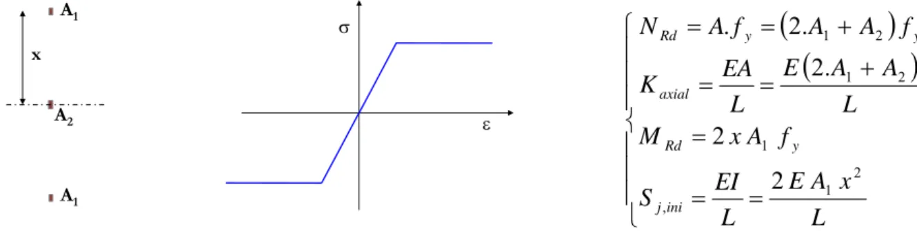
In the first model proposed, not based on the Component Method, the joint is modelled by a unique beam element whose cross-section is composed of three finite elements. The material law is bi-linear for every finite element. The geometry of the cross-section and the material properties are adapted in order to get a mechanical behaviour at room temperature similar to the one calculated analytically. The parameters are the cross-section areas A1 and A2, the distance x, the Young’s modulus and the elastic limit of the bi-linear material law (Figure 5-1). The equations that have to be filled are the axial stiffness, the resistance to normal forces, the rotational stiffness, the resisting bending moment and the element length.
A1 A1 A2 x ε σ
Figure 4-1 : Cross-section geometry (left), material law (right) of the three-fibre beam element and equations of compatibility (joint model n°1)
The main advantages of this model are its relative simplicity to evaluate the parameters and the lightness of the numerical calculations. However, the behaviour of this fictitious element differs from the real joint behaviour in many aspects:
- The behaviour is identical in tension and compression so that it is impossible to model accurately and simultaneously the joint response during the heating and the cooling phases ;
- The interaction between bending and normal forces is not accurate ;
- Despite the fact that the bolts resistance and stiffness decrease more rapidly than mechanical characteristics of carbon steel at elevated temperatures, it is impossible to consider different reduction factors under tensile and compression stresses in that model ;
- It is difficult to take account of the thermal gradient present in the joint zone during the fire ;
(
)
(
)
⎪ ⎪ ⎪ ⎩ ⎪ ⎪ ⎪ ⎨ ⎧ = = = + = = + = = L x A E L EI S f A x M L A A E L EA K f A A f A N ini j y Rd axial y y Rd 2 1 , 1 2 1 2 1 2 2 . 2 . 2 .27
4.1.1.2 Multi-fibre beam elements
The multi-fibre beam elements are constituted of a number of fibres equal to the number of rows identified by the “Component Method”. The resistance and the stiffness of each row are calculated “manually” or with the use of CoP program [J.-P. Jaspart, K. Weynand and al., 1995-2000]. For example, Figure 4-2 shows the cross-section of an extended end-plate connection; the two largest fibres represent the resistance and the stiffness of beam flanges in compression and the three other fibres represent the resistance and the stiffness of bolts rows in tension. The element length and the elastic limit are usually chosen arbitrarily. The cross-section area and the Young modulus are calculated in order to provide the right resistance and stiffness.
Figure 4-2 : Cross-section of the beam element representing an extended end-plate connection
Some new material laws have been defined in the scope of following the non-symmetric mechanical behaviour of connection rows in the simulations: ‘BILIN_TENS’ and ‘BILIN_COMP’ only work in tension or compression respectively. Figure 4-3 shows the mechanical behaviour of the first version of the ‘BILIN_TENS’ material law when submitted to tensile and compressive stresses. In tension, the law is linearly elastic until the yield limit. A linear hardening branch is defined for tensile stresses higher than the yield limit and the unloading is completely elastic. After a loading-unloading cycle in tension, the σ−ε diagram is translated to the right (yellow axis) to account for plastic deformations εpl. The proportionality coefficient of the σ−ε diagram in the compression domain is equal to the hardening modulus. It is necessary to give a minimal stiffness to the elements to avoid buckling. Some improvements will be proposed later (see paragraph 4.1.3).
28
ε
plε
σ
« BILIN_TENS » in tension « BILIN_TENS » in compression
ε
σ
Ε
hardeningΕ
hardeningΕ
0Ε
hardeningΕ
hardeningΕ
0Figure 4-3 : Stress-strain law of BILIN_TENS (Version n°1)
The effect of elevated temperatures on the joint resistance is taken into consideration according to the following approach:
i. Temperature in the joint components is obtained experimentally or numerically ;
ii. Some reduction factors are calculated at each time step for every component ;
iii. The resistances of the components are calculated ;
iv. A fictitious temperature is evaluated in each component to get the right decrease of resistance.
The length of the beam element that represents the effect of the joint is sufficiently short to neglect the thermal elongation in that zone. The necessity to define a fictitious temperature comes from the fact that the reduction of resistance in the component “Bolts in tension” is different from the reduction of resistance in the other components that follow the material law of carbon steel. The bolts resistance decreases quicker than carbon steel due to the thermal treatment they undergo during their fabrication.
The main advantage of the present model is the possibility to follow the individual behaviour of each component, by taking into account the rows activation/deactivation and the presence of plasticity in components. The thermal effect on joint resistance can be accurately considered. This model does not allow getting a realistic evolution of the joint stiffness at elevated temperatures because the “fictitious temperature” defined in a component is evaluated in function of its resistance decrease. The interaction between individual components (group effects) and the resistance in shear can not be considered in that model.
29
4.1.1.3 Multi-elements joint model
Instead of considering an element composed of one fibre per component, the joint may be represented by one truss or beam element per component or row of components (Figure 4-4).
T2
C2
C1
T1 S1
Figure 4-4 : Modelling of a flush end-plate connection
This model allows to define a TRUSS element (S1) that transfers shear forces from beam to columns and to define two elements of a same row in series, allowing the assignment of different material laws in elements of a same row (especially in rows working in tension where end-plate, column and bolts components are put together). However, in comparison with the multi-fibre beam elements, this model necessitates more time for the definition of nodes and elements. Another aspect to investigate is the effect of large displacements: because of the presence of significant deformations during the fire, normal forces create stresses in the shear component and shear forces induce forces in the tension/compression components.
4.1.2 Validation of the BILIN_TENS and BILIN_COMP material laws (Version n°1)
These two new material laws have been inserted in the finite element software SAFIR. In a first approach, BILIN_TENS and BILIN_COMP material laws are defined by four different parameters: Young’s modulus, Poisson’s ratio, yield limit and hardening coefficient. At elevated temperatures, no thermal elongation is considered but the evolution of mechanical properties is similar to carbon steel as defined in the EN 1993-1-2 [CEN, 2005].
In order to check the validity of the BILIN_TENS and BILIN_COMP material laws and their capacity to model the behaviour of joints components, some simple simulations have been run and compared with the expected results.
4.1.2.1 Test n°1: single beam in tension (BILIN_TENS) at ambient temperature.
A one-meter long simply-supported beam has a cross section area equal to 100 cm² and is made of a material that only works in tension. The Young modulus is 210,000 MPa, the
30 hardening modulus is 1,000 MPa and the elastic limit is 26.72 MPa. This section yields under a load equal to 267.2 kN. The beam is gradually loaded in tension until 300 kN, unloaded, progressively reloaded until 350 kN and unloaded again.
During the first loading cycle of the simulation, the beam elongates elastically until the load is equal to the normal plastic load and the hardening branch is reached. The unloading is completely elastic. The second loading phase is elastic until the load reaches the maximal normal force applied during the first cycle (300 kN) and moves on the hardening branch until N = 350 kN. 0 100 200 300 400 500 600 700 800 900 Time N o rm a l For ce - D is p lacem ent Normal Load (kN) Horizontal Displacement (.E-5 m)
Figure 4-5 : Normal force and horizontal displacement in a BILIN_TENS beam in tension
The same test has been realized with the BILIN_COMP material law that only works in compression. The results are identical and will not be presented here.
4.1.2.2 Test n°2: single beam in tension (BILIN_TENS) at high temperature.
At elevated temperatures, no thermal elongation is considered but resistance and stiffness are reduced. Considering the same geometrical and mechanical data as in Test n°1 at several temperatures, the yield force is proportional to the reduction factor for effective yield strength ky,θ defined in the Eurocode for carbon steel.
0 50 100 150 200 250 300 0 200 400 600 800 1000 Temperature (°C) Y iel d F o rce (kN )
Figure 4-6 : Effect of temperature on yield force
N
31 The horizontal displacement at the end of the first loading phase (N = 300 kN) is inversely proportional to the reduction factor for the slope of the elastic range kE,θ defined for carbon steel until 400°C. For temperatures higher than 400°C, the yielding force is reduced and the hardening branch is reached at a lower load level.
Temperature δ δ 20°C / δ kE,θ (°C) (.10-6 m) ( - ) ( - ) 20 340.7 1 1 100 340.7 1 1 200 378.6 0.9 0.9 300 425.9 0.8 0.8 400 486.7 0.7 0.7 500 1542.9 0.22 0.6 600 5645.6 0.06 0.31 700 18372.0 0.02 0.13 800 30083.1 0.01 0.09
Table 4-1 : Horizontal displacement at the rolled support (N = 300 kN)
4.1.2.3 Test n°3: three rows in tension-compression at ambient temperature
Three beams are connected rigidly and submitted successively to tensile and compressive forces. All the beams have the same geometry as in Tests n°1 and 2. External beams work in tension (BILIN_TENS) and the middle one works in compression (BILIN_COMP).
N
δ BILIN_TENS
BILIN_COMP Stiff elements
Figure 4-7 : Static scheme of test n°3
Three consecutive loading-unloading cycles are applied to the structure: a first cycle in tension with a peak value equal to 600 kN, a second cycle in compression reaching -600 kN and a third cycle where the maximal load is 1000 kN.
32 -800 -600 -400 -200 0 200 400 600 800 1000 1200 Tim e A x ia l L o a d ( k N ) Applied Load External Beam (TENS) Middle Beam (COMP)
Figure 4-8 : Applied Load and axial forces in the beams
Figure 4-8 shows the branch of the σ−ε diagram on which each beam is situated during the test and gives the axial forces in the beams at relevant moments. When “BILIN_TENS” elements are loaded in compression and “BILIN_COMP” elements are loaded in tension, it is specified that they are not activated. However, it does not mean that the axial force is equal to 0 because the slope of the σ−ε diagram is equal to the hardening modulus.
33 Load (kN) TENS COMP
1 0 --> 536 Elastic Not activated
536 268 0
2 536 --> 600 Hardening Not activated
600 289 22
3 600 --> 21 Elastic Not activated
21 0 21
4 22 --> 0 Not activated Not activated
0 -7 14
5 0 --> -42 Not activated Not activated
-42 -21 0
6 -42 --> -312 Not activated Elastic
-312 -22 -268
7 -312 --> -600 Not activated Hardening
-600 -118 -364
8 -600 --> -232 Not activated Elastic
-232 -116 0
9 -232 --> 0 Not activated Not activated
0 -39 78
10 0 --> 696 Elastic Not activated
696 289 118
11 696 --> 1000 Hardening Not activated
1000 390.5 219
12 1000 --> 217 Elastic Not activated
217 0 217
13 217 --> 0 Not activated Not activated
0 -72.5 145
Table 4-2 : Axial forces in BILIN_TENS and BILIN_COMP elements
Due to that assessment, elements are submitted to significant normal loads in the domain they are not expected to work. Table 4-2 shows that, when the applied load comes back to 0 at the end of a loading-unloading cycle, there is simultaneously significant compressive stresses in “BILIN_TENS” elements and significant tensile stresses in “BILIN_TENS” elements.
4.1.3 Validation of the BILIN_TENS* and BILIN_COMP* material laws (Version 2)
In cross-sections where every finite element is constituted of a unique material law, it is not allowable to assign a zero or very low slope to the “inactivated” domain of the σ−ε diagram. However, assigning a too high value to that slope leads to wrong stresses distributions. In order to prevent from the problems exposed in the paragraph 4.1.2, some adapted “BILIN_TENS*” and “BILIN_COMP*” material laws have been defined in SAFIR program.
34
ε
plε
σ
« BILIN_TENS* » in tension « BILIN_TENS* » in compression
ε
σ
Ε
hardeningΕ
inactiveΕ
0Ε
inactiveΕ
hardeningΕ
0Figure 4-9 : Stress-strain law of BILIN_TENS* (Version n°2)
The same three tests as those performed with the first version of new material laws have been run. The geometrical properties, the mechanical properties and the loading are kept unchanged except the hardening modulus, equal to 5,000 MPa, and the modulus of the “inactive branch”, equal to 100 MPa.
Under this assumption, Test n°1 and Test n°2 give identical results in the elastic branch and plastic deformations are five times smaller in the present case.
4.1.3.1 Test n°3: three rows in tension-compression at ambient temperature
The system of three connected beams is submitted to three loading-unloading cycles. In the present case, the ratio between the stiffness of the elements on the hardening branch of the σ−ε diagram and the stiffness of the elements loaded in their “inactive domain” is equal to 50. No more significant “parasitic loads” are observed in “BILIN_TENS*” elements under compressive loading cycles and “BILIN_COMP*” elements under tensile loading cycles (Figure 4-10). -600 -400 -200 0 200 400 600 800 1000 1200 Tim e A x ia l L o ad ( k N ) Applied Load External Beam (TENS) Middle Beam (COMP)
35
Figure 4-10 : Normal force in the components of the system
The evolution of horizontal displacement is given in Figure 4-11. At the transition between the first two cycles, the resulting displacement comes back to 0 before the BILIN_COMP* beam (middle beam) starts to adopt an elastic behaviour. After the second cycle (compression cycle) and as soon as the tensile loads are applied, the displacement recovers the plastic displacement reached at the end of the first loading cycle in tension.
-4 -3 -2 -1 0 1 2 3 H o ri z o n tal d is p lacem en t (m m ) N δ
Figure 4-11 : Horizontal displacement at the load position
This is in complete agreement with the realistic behaviour of a joint. In a flush or extended end-plate joint, the bolts rows only work in tension if the bolt nut and bolt head are in contact with the column flange and the end-plate respectively. In compression, the contact between the beam flange and the end-plate is needed to make the load transfer possible.
After successive cycles producing plastic deformations in tension and compression, the contact requested to mobilise a row in tension (respectively in compression) is obtained when the horizontal displacement reaches the maximal plastic displacements undergone during the previous tensile (respectively in compression) cycles. The results obtained with “BILIN_TENS*” and “BILIN_COMP*” material laws defined in SAFIR are in agreement with that reality.
4.2 Presentation of CoP
CoP program [J.-P. Jaspart, K. Weynand and al., 1995-2000] is a tool aimed at designing steel joints submitted to a combination of axial forces, shear forces and hogging or sagging bending moments according to Eurocode 3 recommendations. It was developed at the Universities of Aachen (Germany) and Liège. The calculation of joints resistance and stiffness is based on the analytical Component Method.
36 For a large variety of connections typologies, the software CoP can calculate:
- the plastic bending resistance MRd ; - the elastic bending resistance Me ; - the initial stiffness Sj,ini ;
- the shear resistance VRd ; - the collapse mode and ductility.
The analytical determination of these results is based on the Component Method, described in chapter 2.4.4 and recommended by the EN 1993-1-8 [CEN, 2003].
37
5 Numerical Simulations of the experimental tests
5.1 Tests realized at the University of Manchester
In his paper, Liu describes the results of 15 experimental tests [T.C.H. Liu., 1999]:
• 2 tests on simply-supported beams
• 3 tests on substructures with web-cleats connections • 10 tests on substructures with flush end-plate connections
The three tests on web-cleats connections have not been modelled in the FE software SAFIR because of the difficulty to model the action of this type of joint. As mentioned previously, the resistance of this joint is not negligible and its behaviour is completely modified when the rotation of the joint is sufficient to create a contact zone between the beam lower flange and the column.
5.1.1 Thermal Analyses
In every test, the furnace temperature is controlled to follow the ISO834 standard curve. In order to simulate the heat-sink effect due to concrete slab, the top flanges were wrapped with 15 mm thick ceramic fibre blanket. The column and the connections were fire-protected by a 50 mm thickness of this material.
The distribution of temperature in the beam has been calculated with SAFIR by considering that the upper flange frontiers are adiabatic. This assumption is not completely realistic because the insulating material avoids any heat flux during a limited period of time but the precision is sufficient to make this thermal distribution acceptable in the mechanical analysis (Figure 5-1).
38 -100 0 100 200 300 400 500 600 700 800 900 1000 0 5 10 15 20 25 30 35 40 45 Time (min) T e m p er atu re (°C )
Test - B o tto m Flange Test - Web Test - To p flange SA FIR - B o tto m Flange SA FIR - Web SA FIR - To p flange
Figure 5-1 : Comparison between numerical and measured temperatures in the mid-span cross-section 5.1.2 Mechanical Analyses
5.1.2.1 Simply-supported beams
The failure of a simply-supported beam is reached when the first plastic hinge is formed in the most critical cross-section or zone. In this case, the analytical calculation of the beam fire resistance consists in evaluating the time where the reduction of the resisting bending moment due to the elevation of temperature is equal to the load ratio. The actual load ratios are lower than the design load ratios because the actual yield strength of steel at room temperature, measured on coupon tests, is higher than 275 MPa.
Assuming that the temperature is constant on the complete beam cross-section, the critical temperature calculated analytically is given in (Table 5-1):
Design Actual Critical
Load Ratio Load Ratio Temperature
0.5 0.42 620°C
0.7 0.58 565°C
Table 5-1 : Critical temperature of tested simply-supported beams
The comparison between the experimental and numerical results is given in Figure 5-2. The failure of the beam is reached in the numerical simulations for lower temperatures than experimentally. The bottom flange temperature at the failure in the test is about 35°C higher than the one leading to the failure in the numerical model. The mid-span deflection increases more quickly in the numerical simulations.
39 0 100 200 300 400 500 600 700 800 0 50 100 150 200 250 300 350 400 Mid-span Deflection (m m ) B o tt o m f lan g e T e m p er at u re ( °C ) Test - L.R.= 0.5 Test - L.R.= 0.7 SA FIR - L.R.= 0.5 SA FIR - L.R.= 0.7
Figure 5-2 : Comparison of numerical and analytical deflections in simply-supported beams
Comparing the numerical and experimental results with the analytical solution is not simple because of the thermal protection on the upper flange and the non-uniform distribution of temperature in the beam cross-section. Figure 5-3 shows the distribution of temperature at failure time for two values of the design load ratio.
TIME: 860 s ec 679.40 640.38 601.35 562.33 523.30 484.28 445.25 406.23 367.20 TIME: 790 s ec 658.20 618.00 577.80 537.60 497.40 457.20 417.00 376.80 336.60
Figure 5-3 : Distribution of temperature in UB 178x102x19 at failure time (a) Design L. R. = 0.5 - Time = 860 sec (b) Design L. R. = 0.7 - Time = 790 sec
5.1.2.2 Substructures with flush end-plate connections – BEAM elements
The design moment capacity of the flush end-plate connections used in this series of tests has been calculated by Liu as equal to 30 kN.m. The end-plate connections were estimated to provide a rotational stiffness of 14,000 kN.m/rad. By using CoP software and considering unitary partial coefficients on the elastic limit of steel, the design resisting moment is 25.20 kN.m. The failure mode is the column web in shear and the initial rotational stiffness is 2,940 kN.m/rad.
The origin of these significant differences has not been detected because the article describing the experimental tests is the only piece of information available. No more documentation
40 could be obtained. The question about the plate thickness (10 mm mentioned in the text and 12 mm on the drawing) does not explain such an important divergence on the evaluation of the initial rotational stiffness of the joint.
The numerical simulations of the 10 tests performed on substructures with flush end-plate connections have been modelled with beam elements because no local instabilities have been observed during these tests, except for the test with the highest load ratio and the lowest axial restraints (Load Ratio = 0.9 and k = 8 kN/mm). A shell model has been run in this particular case and will be discussed later.
As the measurements have been stopped at the beginning of the cooling phase, the beam is exclusively subjected to compressive axial thrusts. The presence of group mechanisms in the connections is less likely to happen than under pure bending. The action of the connections has been represented by short beam elements where each row (working in tension or compression) is substituted by a fibre whose section area and material properties are adapted to match with the resistances and the stiffnesses calculated analytically without considering group effects.
The correlation between the vertical deflections measured during the experimentations and those calculated numerically with beam elements are very good (see Appendix B). Similarly to the simply-supported beams, the numerical results give smoother curves; during the real test, the mid-span vertical displacement does not vary much until the formation of the plastic hinges. In every simulation, beam mechanisms lead the structure to failure.
In tests with axial restraints equal to 35 kN/mm and 62 kN/mm, the difference between axial thrusts obtained numerically and experimentally is due to the fact that the restraining system is not fully effective at the beginning of the tests. Therefore, the initial low axial stiffness of the end restraint induces a slower rate of increase in the measured compression force than expected. In tests where the axial restraining system is only due to the stiffness of the column in bending (k = 8 kN/mm), a slight difference is noticed at elevated temperatures. The compression forces are more important in the tests and this is in agreement with the “more rigid” behaviour observed in the displacement curves. For every axial restraint, the influence of the load ratio on the axial thrusts is very low.
The evolution of the hogging bending moments at the junction between the beam and the column is influenced by the connection behaviour. As referred previously, the analytical calculation of the resisting moment and the initial rotational stiffness according to the Component Method lead to lower values than those mentioned by Liu.
41
5.1.2.3 Substructures with flush end-plate connections – SHELL elements
Numerical simulations using BEAM elements do not allow taking the local instabilities into account because this theory assumes that the cross-section of elements remain planary. The presence of hogging bending moments and compressive axial thrust near the connection increases much the risk of local buckling in the beam lower flanges. Moreover, top flanges are strongly exposed to fire and their stiffness decreases more quickly than the bottom flanges. Figure 5-4 shows the model and the meshing of the sub-structure used to analyze its numerical response in the case with a Load Ratio equal to 0.9 and without any additional struts (k = 8 kN/mm).
Y
Figure 5-4 : Meshing of the substructure and modelling of the joint
The end-plate connection is modelled according an “adapted version” of the Component method. The components dealing with the resistance and stiffness of the beam, the column and the plate are already taken in consideration with the SHELL finite elements. Two rows infinitely stiff and resistant in compression are defined between the beam flanges and the column for transmission of compression forces. Each row is modelled by seven TRUSS elements. The three rows working in tension are represented by six TRUSS elements whose material and geometrical properties are defined in order to get a mechanical behaviour that matches with the real behaviour of bolts.
The vertical displacements of the two nodes of a TRUSS element are imposed to be identical so that shear forces are transferred from the beam to the column. The effect of shear on the resistance of bolts is consequently not taken into account. This modelling assessment also causes an under-estimation of the joint capacity of rotation and an over-estimation of the joint stiffness because the column is assumed not to rotate at all. In the present test, the column is very stiff and is completely protected.
42 A stiffener has been added in the cross-section where the load is applied to avoid a failure due to localised stresses that has not been observed during the experimental tests. The temperature in the stiffener has been defined as equal to temperature in the beam so that no thermal stresses are created. The symmetry of the sub-structure has been considered to reduce the number of finite element and the computer calculation-time.
Figure 5-5 shows that the failure is obtained at a lower temperature than expected with the SHELL model. This is due to the model used for the joint. Imposing that the vertical displacements are equivalent at the extremities of the TRUSS elements representing the action of joint components is acceptable for low joint rotations. Under the effect of thermal gradient and vertical loading, significant rotations tend to develop in the joint. Avoiding the rotation of the TRUSS elements increases the rotational stiffness of the joint noticeably. In consequence, the joint is submitted to higher hogging bending moments and the failure is obtained prematurely. 0 100 200 300 400 500 600 700 800 0 20 40 60 80 100 120 Vertical displacement (mm) B o tt om F lan ge Te m p e rat ur e ( °C ) Test SAFIR BEAM SAFIR SHELL
Figure 5-5 : Comparison between vertical displacements with BEAM and SHELL elements
5.2 Tests realized in the scope of COSSFIRE project
5.2.1 Thermal Analyses
The thermal analyses have been realised with 3D solid elements and the shadow effect is taken into account by reducing the materials relative emissivity according to Eurocode recommendations. Three different correction factors for the shadow effect are used in the three following zones: beam and end-plate, part of the column situated below the end-plate and part of the column situated between the end-plates of the joint (Figure 5-6). The emissivity factor is not modified in the slab and the unheated part of the column, situated
43 above the slab.
Figure 5-6 : Subdivision of the joint in zones characterised by different “shadow effect” factors
The comparisons between numerical and experimental temperatures in the plate, the beam, the bolts and the column show a good agreement (see Appendix C) in both tests. It should be mentioned that the low heating speed (10°C/min) explains partially why the numerical and experimental curves fit so well on the graphs.
5.2.2 Mechanical Analyses
The geometry of the sub-structure and the 3-D numerical model are shown in Figure 5-7. The system used to provide axial restraints has been substituted by an elastic spring in the numerical simulation. The rotation and the out-of-plane displacement are the beam are fixed at the position of the loading jack.
F0 F0 F0 F0 F0 F0 F0 F0 F0 F0 F0 F0 F0 F0 F0 F0 F0 F0 F0 F0 F0 F F0 F0 F0 F0 F0 F0 F0 F0 F0 F0 F0 F0 F0 F0 F0 F0 F0 F0 F0 F0 F0 F0 F0 F0 F0 F0
Figure 5-7 : Structural model of the tests n°1&2
HEA300.tem HEA220cold.tem IPE300hot.tem IPE300cold.tem HEA220hot.tem HEB140.tem J1.tem IPE300coldbilin.te
44 The two tests have been modelled with two steel resistances of carbon steel (235 MPa & 355 MPa) because no coupon tests have been performed on the grade S235 steel used. As the real yield strength of S235 steel is usually closer to 355 MPa than 235 MPa, the two simulations have been run. The mean value of the ultimate resistance of bolts measured during the four tests realised at room temperature has been chosen as the bolts resistance in tension.
In Test n°1, the failure is reached when the furnace temperature is equal to 797 °C (t = 4185 sec = 70 min) and the comparisons between numerical and experimental values of the vertical displacement at the jack position and the horizontal displacement at the beam extremity, given in Figure 5-8, are very good. The failure mode is a plastic beam mechanism: two plastic hinges appear in the studied joint and the section where the vertical loading is applied.
-50 0 50 100 150 200 250 300 350 0 20 40 60 80 100 120 140 Tim e (m in) D isp lacem en t ( m m ) Tes t Metz n°1 SAFIR S235 SAFIR S355 -50 -40 -30 -20 -10 0 10 20 30 40 50 0 20 40 60 80 100 120 140 Tim e (m in) D isp lacem en t ( m m ) Test Metz n°1 SAFIR S235 SAFIR S355
Figure 5-8 : Test n°1 – (a) Loading jack : vertical displacement - (b) Beam extremity : horizontal displacement
In Test n°2, no failure is observed until the end of the test (12550 sec = 209 min). The horizontal displacement of the beam extremity obtained numerically follows the experimental curve with a good precision. However, the vertical displacement at the jack position given by the numerical simulation is lower than the measured displacement, mainly during the cooling phase (Figure 5-9).
45 0 50 100 150 200 250 0 50 100 150 200 250 Tim e (m in) D is p la c e me nt (m m) Test Metz n°2 SAFIR S235 SAFIR S355 -30 -20 -10 0 10 20 30 40 50 0 50 100 150 200 250 Tim e (m in) D isp la cem en t ( m m ) Test Metz n°2 SAFIR S235 SAFIR S355
Figure 5-9 : Test n°2 – (a) Loading jack : vertical displacement - (b) Beam extremity : horizontal displacement
The correlation between the results of the mechanical numerical analyses and the experimental results is good for tests n°1 & 2.