blJ SHERBROOKE
Faculte de genie
Departement de genie civil
PRESSION EXERCEE SUR LE COFFRAGE
PAR LE BETON AUTO-PLACANT
FORMWORK PRESSURE EXERTED BY
SELF-CONSOLIDATING CONCRETE
These de doctorat es sciences appliquees
Speciality : genie civil
Membres du jury :
Kamal Khayat, directeur de these Nicolas Roussel
Olafur Wallevik Emmanuel Attiogbe Joseph Assaad Brahim Benmokrane
Ahmed Fathy OMRAN
1*1
Published Heritage Branch 395 Wellington Street OttawaONK1A0N4 Canada Direction du Patrimoine de I'edition 395, rue Wellington OttawaONK1A0N4 CanadaYour file Votre reference ISBN: 978-0-494-52850-1 Our file Notre reference ISBN: 978-0-494-52850-1
NOTICE: AVIS: The author has granted a
non-exclusive license allowing Library and Archives Canada to reproduce, publish, archive, preserve, conserve, communicate to the public by
telecommunication or on the Internet, loan, distribute and sell theses
worldwide, for commercial or non-commercial purposes, in microform, paper, electronic and/or any other formats.
L'auteur a accorde une licence non exclusive permettant a la Bibliotheque et Archives Canada de reproduire, publier, archiver, sauvegarder, conserver, transmettre au public par telecommunication ou par Plnternet, preter, distribuer et vendre des theses partout dans le monde, a des fins commerciales ou autres, sur support microforme, papier, electronique et/ou autres formats.
The author retains copyright ownership and moral rights in this thesis. Neither the thesis nor substantial extracts from it may be printed or otherwise reproduced without the author's permission.
L'auteur conserve la propriete du droit d'auteur et des droits moraux qui protege cette these. Ni la these ni des extraits substantiels de celle-ci ne doivent etre imprimes ou autrement
reproduits sans son autorisation.
In compliance with the Canadian Privacy Act some supporting forms may have been removed from this thesis.
Conformement a la loi canadienne sur la protection de la vie privee, quelques formulaires secondaires ont ete enleves de cette these.
While these forms may be included in the document page count, their removal does not represent any loss of content from the thesis.
Bien que ces formulaires aient inclus dans la pagination, il n'y aura aucun contenu manquant.
1*1
Canada
Self-consolidating concrete (SCC) is an emerging technology that utilizes flowable concrete that eliminates the need for consolidation. The advantages of SCC lie in a remarkable reduction of the casting time, facilitating the casting of congested and complex structural elements, possibility to reduce labor demand, elimination of mechanical vibrations and noise, improvement of surface appearance, producing a better and premium concrete product.
While SCC has been successfully used in North America in the precast industry, a certain number of technical issues have slowed down its use in cast-in-place applications, in particular due to the lack of knowledge on the lateral pressure that such concrete can exert on formwork systems. This prompts contractors and engineers, as recommended by ACI 347R-03 (Guide to Formwork for Concrete), to design for full hydrostatic pressure, which increases drastically the cost of construction made of SCC. This adverse effect compromises profitability, due to the need to design for robust formwork construction and detailed joint sealing.
The research focussed on capturing existing knowledge and making recommendations for current practice. An experimental program was undertaken at the Universite de Sherbrooke to evaluate the lateral pressure developed by SCC mixtures. A portable devise (UofS2 pressure column) for measuring and predicting lateral pressure and its rate of decay of SCC was developed and validated. The UofS2 pressure column is cast with 0.5 m high fresh concrete and air pressure is introduced from the top to simulate casting depth up to 13 m. Then, develop and implement test method for field evaluation of relevant plastic and thixotropic properties of SCC that affect formwork pressure were done. Portable vane (PV) test based on the hand-held vane test method used to determine the undrained shear strength property of clay soil was the first setup as well as the inclined plane (IP) test. The IP device involves slumping a small concrete cylinder on a horizontal plate and then lifting up the plate at different durations of rest until the slumped sample
starts to move. Identifying role of material constituents, mix design, concrete placement characteristics (casting rate, waiting periods between lifts, and casting depth), temperature, and formwork characteristics that have major influence on formwork pressure exerted by SCC were evaluated in laboratory and validated by actual field measurements. Relating the maximum lateral pressure and its rate of decay to the plastic properties of SCC were established. In the analytical
as well as chart diagrams to predict formwork pressure that can be exerted by SCC on column and wall elements were derived and reported.
In general, the results obtained show that measured lateral pressure is lower than corresponding hydrostatic pressure. The study has shown that lateral pressure exerted by SCC is closely related to the structural build-up at rest (or thixotropy) of SCC. The latter can be controlled using different mixture proportionings, material constituents, and chemical admixtures. SCC mixture with a high rate of structural build-up at rest can develop low lateral pressure on formwork. Increased rate of structural build-up at rest can be ensured by incorporating a greater volume of coarse aggregate, lower paste volume, and/or lower sand-to-total aggregate ratio. Incorporating coarse aggregate of larger maximum size could also increase the thixotropy and hence reduce the lateral pressure. This can also be achieved by reducing the workability of SCC using less HRWRA concentration. Indeed, all mixture factors have been replaced by measuring the rate of structural build-up at rest (or thixotropy) using the developed portable vane and inclined plane field-oriented test as well as the modified Tattersall MK-III concrete rheometer. On the other hand, increasing or maintaining the concrete temperature at a certain level plays an important role to reduce the lateral pressure. The higher concrete temperature can accelerate the heat of hydration of cement with water and increase the internal friction leading to higher thixotropy.
Controlling the placement rate has a great impact on the resultant lateral pressure of SCC. The lateral pressure can be reduced by slowing down the casting rate, as concrete has more time to build-up. However, this can slow down the rate of construction. The casting rate should be optimized to yield a cost effective formwork system. Pausing the continuous casting by a waiting period can reduce the exerted lateral pressure.
The research investigation could accelerate the acceptance and implementation of SCC technology in cast-in-place applications, which is the preponderate business of the ready mixed concrete suppliers. The research findings could also contribute to the removal of some of the major barriers hindering the acceptance of SCC in cast-in-place applications and provide the industry with much needed guidelines on formwork pressure.
Le beton auto-placant (BAP) est une technologie emergente qui utilise un beton fluide qui elimine le besoin de consolidation. Les avantages du BAP sont la reduction remarquable du temps de mise en place, la facilite de mise en place dans les elements structuraux encombres et complexes, la possibility de reduire la demande de main-d'ceuvre, l'elimination des vibrations mecaniques et du bruit et 1'amelioration de l'apparence exterieure, en produisant un beton de meilleure qualite.
Tandis que le BAP a ete employe avec succes en Amerique du Nord dans l'industrie prefabriquee, un certain nombre de preoccupations techniques ont ralenti son utilisation dans les applications coulees sur place, en particulier dues au manque de connaissance sur la pression laterale qu'un tel beton peut exercer sur des systemes de coffrage. Cela incite les entrepreneurs et les ingenieurs, tel que recommande par l'ACI 347R-03 (Guide de coffrage pour le beton), a concevoir les coffrages pour une pression hydrostatique pleine, ce qui augmente radicalement le cout des constructions fait en BAP. Cet effet nuisible compromet la rentabilite, due a la necessite de concevoir des coffrages robustes et des joints d'etancheite detailles.
La recherche s'est concentree sur le rassemblement des connaissances existantes et a emis des recommandations pour la pratique actuelle. Un programme experimental a ete entrepris a l'Universite de Sherbrooke afin d'evaluer la pression laterale developpee par des melanges de BAP. Un appareil portatif (colonne de pression UdeS2) pour mesurer et prevoir la pression laterale et le taux de diminution de la pression d'un BAP a ete developpe et valide. La colonne de pression UdeS2 est coulee avec 0.5 m de haut de beton frais et de l'air est introduit sous pression a partir du dessus pour simuler une profondeur jusqu'a 13 m de beton frais. Par la suite, le developpement et l'application d'une methode d'essai pour 1'evaluation en chantier des proprietes plastiques et thixotropiques d'un BAP, qui affectent la pression de coffrage, ont ete faits. Le premier montage retenu est l'essai portatif de la palette, base sur l'essai du scissometre employe pour determiner la resistance au cisaillement non drainee d'un sol d'argile. Le deuxieme montage retenu est l'essai du plan incline (PI). Le dispositif du PI consiste a affaisser un petit cylindre de beton frais sur la surface horizontale et ensuite de soulever cette surface vers le haut pour differents temps de repos, jusqu'a ce que l'echantillon affaisse commence a s'ecouler. L'identification du role des materiaux,
coffrage, qui ont une influence majeure sur la pression de coffrage exercee par les BAP, ont ete evaluees au laboratoire et valides par des mesures reelles sur le terrain. Les relations entre la pression laterale maximum et son taux de diminution par rapport aux proprietes plastiques du BAP ont ete etablies. Dans la partie de Panalyse de la recherche, des facons efficaces de reduire la pression laterale ont ete propose en developpant une expertise dans la formulation de BAP et en dormant des directives pratiques. Diverses equations ainsi que des diagrammes pour predire la pression qui peut etre exercee par des BAP sur des elements de colonne et de mur de coffrage ont ete derivees et rapportees.
En general, les resultats obtenus demontrent que la pression laterale mesuree est inferieure a la pression hydrostatique correspondante. L'etude a demontre que de la pression laterale exercee par le BAP est etroitement liee a la restrucruration au repos (ou thixotropie) du BAP. Ce dernier peut etre controle en utilisant differentes proportions de melange, differents materiaux et des adjuvants chimiques. Un melange de BAP avec un taux eleve de restrucruration au repos peut developper une pression laterale tres faible sur le coffrage. Un plus grand taux de restrucruration au repos peut etre obtenu en incorporant un plus grand volume de gros granulats, en diminuant le volume de pate et/ou en abaissant le ratio global de sable-granulat. Incorporer des granulats de plus grande dimension permettrait aussi d'augmenter la thixotropie et done reduire la pression laterale. Ceci peut egalement etre realise en reduisant l'ouvrabilite du BAP en utilisant moins de superplastifiant (S.P.). En effet, tous les facteurs du melange ont ete remplaces en mesurant le taux de restrucruration au repos (ou thixotropie) avec les essais empiriques de palette portative et de plan incline developpes ainsi qu'avec le rheometre de beton modifie Tattersall MK-III. D'un autre cote, l'augmentation ou le maintien de la temperature du beton a un certain niveau joue un role important pour reduire la pression laterale. Une temperature du beton plus elevee peut accelerer l'hydratation du ciment avec l'eau et augmenter la friction interne, menant a une thixotropie plus elevee.
Le controle du taux de placement a un grand impact sur la pression laterale du BAP. La pression laterale peut etre reduite en reduisant le taux de mise en place, ce qui fait en sorte que le beton a plus de temps pour se structures Cependant, ceci peut ralentir le taux de construction. Le taux de mise en place devrait etre optimise pour arriver a un systeme de coffrage rentable. Faire une
La presente recherche pourrait accelerer l'acceptation et 1'application de la technologie de BAP dans les applications coulees sur place, qui est une affaire encourageante des fournisseurs de beton pret a l'emploi. Les resultats de la recherche pourraient aussi contribuer a l'elimination des barrieres empechant l'acceptation des BAP dans les applications coulee en place et dormer a rindustrie des guides sur les pressions laterales.
Mots de cles
Beton auto-pla9ant (BAP), pression laterale, coffrage, pression lateral sur colonne et mur, thixotropie, restructuration au repos, et modeles de prediction
&Tj>?wckm< ^JzM!tity& a?&//?w afataifa&p <JMwtizm wA& mme/& #fe e#%Afen<^ dmifrw mp t^J^afe cmt/Aa#e made a- && a^^^e/^^seJfr m^^S.
Foremost, praise and thanks go to my Creator and Provider (Allah) for his uncounted grace undeservingly bestowed upon me. "Glory be to You, we have no knowledge except what You have taught us. Verily, it is You, the All-Knower, the All-Wise."
The author would like to express his greatest appreciation and thanks to his supervisor Prof. Kamal Khayat for offering him the opportunity to work on such a challenging subject. The author is proud to work with him. All of the guidance, insight, helpful advice, and encouragement provided throughout the course of the thesis are greatly appreciated. The author has learned a lot from his thorough knowledge and experience as well as from his nice and decent personality. Despite his busy schedule, Prof. Khayat was always available to follow up and suggest new and bright ideas for improving the final quality and impact of the work. The Author can hardly find the right words to express the extent of his gratitude and thanks.
The Author is greatly indebted to Drs. Ammar Yahia, Trimbak Pavate, Peter Billberg, and Ahmed El-Sayed for their cooperation, consulting, and friendship during the research. The author also thanks his colleague Yacine Elaguab for his cooperation and assistance. Eng. Elaguab, during his entire master program, had worked with the author in the same field of study.
The Author also thanks the professors of Civil Engineering Department and all the faculty staff he has interacted with. Special thanks to Mrs. Christine Couture, the research secretary and Mrs. Marielle Beaudry, the department secretary. Appreciation is expressed to Mr. Claude Faucher who helped in manufacturing and solving any technical problems concerning the test setups used in entire research. The kind cooperation of all the professors, research assistants, technicians, and graduate students of the Cement and Concrete Research Group at the Universite de Sherbrooke is also acknowledged. The Author cannot forget to acknowledge all friends he has gained during his study who made the stay at Sherbrooke enjoyable. Great acknowledgement is forwarded to his colleagues at University of Northwestern and the members of CTLGroup who participated in part of the study.
The Author also wishes to thank Lafarge Laboratory Research Center, France for funding part of his research. Also, thanks to Ready-Mix Concrete Research Foundation (RMC) and American Concrete Institute-Strategic Development Council (ACI-SDC) for funding part of the research.
The Author is thankful to the members of the dissertation committee; Prof. Nicolas Roussel, Prof. Olafur Wallevik, Dr. Emmanuel Attiogbe, Dr. Joseph Assaad, and Prof. Brahim Benmokrane for their valuable comments and advices.
The author wishes to express his greatest and profound gratitude to his parents, brother, sisters, and mother-in-law for their praying to him. Finally, the author wishes to thank his wife Nancy for her useful discussions, love, and happiness she brought to him. The life at Sherbrooke would not have been so full without his wife and his smiley kids Mustafa and Mariam.
ABSTRACT i RESUME iii DEDICATION vi ACKNOWLEDGMENTS vii
CONTENTS vui SYMBOLS AND NOTATIONS xiii
CHAPTER 1 INTRODUCTION 1
1.1 Introduction 1 1.2 Objectives 4 1.3 Thesis outline 5
CHAPTER 2 REVIEW ON FORMWORK PRESSURE AND FUNDAMENTALS OF
RHEOLOGY 8
2.1 Introduction 8 2.2 Review of various recommendations for formwork design 8
2.2.1 Models proposed to evaluate formwork pressure 10
A. Rodin's models [1952] 10
B. ACI models 11 C. Models of German Standard [DIN 18218, 1980] 13
D. CIRIA 108 design models [1965 - 1978] 14
E. Gardner's models [1980 -1984] 15 F. Models of French Standard [NF P93-350, 1995] 16
G. Comparison between models 16 2.2.2 Theoretical models to predict formwork pressure 17
A. Vanhove and co-authors' model [2004] 17 B. Roussel and Ovarlez's model [2005] 18 C. Graubner and Proske's model [2005A] 23 D. Khayat and Assaad's model [2005A] 27 2.3 Relationship between form pressure and rheology of SCC 32
2.3.1 Thixotropy of cement-based materials 32
2.3.2 Concrete rheometer 35 2.3.3 Dynamic yield stress and plastic viscosity 37
2.3.4 Approaches to quantify thixotropy of concrete 38
A. Hysteresis curves 39 B. Structural breakdown curves 40
C. Apparent viscosity 43 D. Static yield stress at rest 43 E. Structure build-up at rest minus irreversible structure 45
2.3.5 Relationships between lateral pressure and rheological properties 46
2.4 Parameters affecting formwork pressure and thixotropy 46
2.4.1 Material properties 47 A. Composition and content of binder 47
B. Characteristics of coarse aggregate 49
C. Water content and w/cm 51
2.4.2 Consistency level 51 2.4.3 Placement conditions 52
A. Placement rate 52 B. Placement method 54 C. Ambient and concrete temperature 55
B. Type of formwork surface material 58
2.5 Lateral pressure measuring systems 59 2.5.1 Instruments and devices to monitor lateral pressure 59
2.5.2 Pore waterpressure measurements to determine lateral pressure 62
2.6 Case studies for formwork pressure exerted by SCC 67
2.7 Concluding remarks 75
CHAPTER 3 MATERIALS AND MIX DESIGNS 76
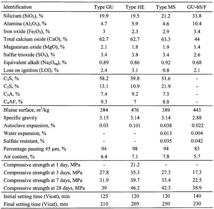
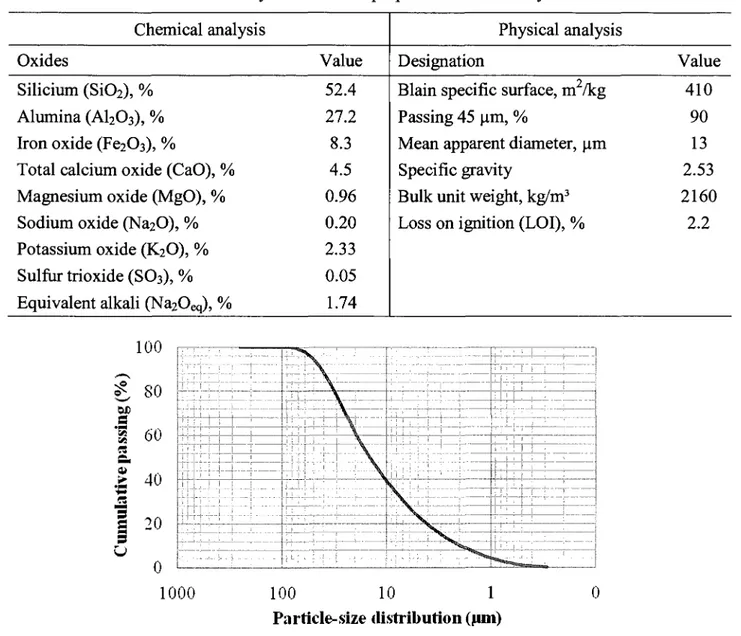
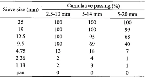
3.1 Materials 76 3.1.1 Cement 76 3.1.2 Limestone filler 77 3.1.3 Fly ash 78 3.1.4 Aggregate 79 3.1.5 Chemical admixtures 81 3.2 Mixture composition 82 3.3 Mixing and testing sequence 82
CHAPTER 4 METHODOLOGY FOR LATERAL PRESSURE MEASUREMENTS 90
4.1 Introduction 90
4.1.1 Evaluation of initial maximum formwork pressure 90
4.1.2 Evaluation of lateral pressure decay 91 4.1.3 Evaluation of formwork width on lateral pressure 91
4.2 Data acquisition 93 4.3 Measuring systems 93 4.4 Calibration of pressure sensors 94
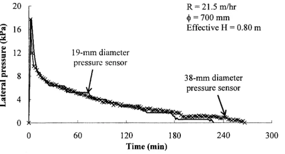
4.5 Pressure sensor configurations (19 mm vs. 38 mm) 95
CHAPTER 5 DEVELOPMENT PORTABLE DEVICE TO MEASURE SCC FORMWORK
PRESSURE 96
5.1 Introduction 96 5.2 Research significance and objectives 96
5.3 Testing program 97 5.4 Fresh concrete properties 97
5.5 Reduce concrete height in the UofSl pressure column 99
5.6 Design of new pressure device 99 5.7 Successive reduction of concrete plug in the UofS2 pressure column 101
5.8 The UofS2 pressure column vs. 3-m free standing PVC column 104
5.9 Lateral pressure decay 106 5.10 Repeatability responses of the UofS2 pressure column 108
5.11 Evaluation of key parameters affecting form pressure 109
5.11.1 Effect of casting rate 109 5.11.2 Effect of slump flow 110 5.11.3 Effect of VMA and HRWRA contents 112
5.11.4 Effect ofpaste volume 113 5.11.5 Effect of maximum-size of aggregate 115
5.12 Conclusions 116
CHAPTER 6 FIELD-ORIENTED TEST METHODS TO EVALUATE STRUCTURAL
BUILD-UP AT REST OF SCC 117
6.1 Introduction H7 6.2 Research significance and objectives 118
6.3 Testing program H8
6.4 Field-oriented test methods to evaluate structural build-up at rest of SCC 119
6.4.2 Inclined plane 123 A. Background 123 B. Development of the IP test for SCC 124
C. Calculation of static yield stress from the IP test 126 6.4.3 Evaluating repeatability of field-oriented test methods 126 6.5 Correlating field-oriented method responses to rheometric measurements 127
6.5.1 Correlation between initial responses 128 A. Correlations between initial static yield stress determined from PV and IP tests 128
B. Correlations between initial static yield stress determined from field-oriented and
rheometric test methods 129 C. Correlations between initial static yield stress determined from field-oriented tests and
initial drop in apparent viscosity at 0.7 rps determined from concrete rheometer 130 D. Correlations between initial static yield stress determined from field-oriented tests and
initial breakdown area determined from rheometric test method 131
6.5.2 Correlation between time-dependent responses 132 A. Correlating time-dependent static yield stress determined from field-oriented tests 132
B. Correlating time-dependent static yield stress determined from field-oriented tests and
rheometric test 132 C. Correlating time-dependent static yield stress determined from field-oriented tests to
time-dependent drop in apparent viscosity at 0.7 rps determined from rheometric test 133
6.6 Conclusions 135
CHAPTER 7 EFFECT OF SCC MIX DESIGN ON FORMWORK PRESSURE
CHARACTERISTICS 136
7.1 Objectives 136 7.2 Testing program 136 7.3 Test results of Phase I 139
7.3.1 Effect of<)),S/A and Vca on SCC formwork pressure 139
7.3.2 Effect of <j), S/A, and Va on thixotropy of SCC 142
7.3.3 Relationship between ICo and structural build-up at rest 142 7.3.4 Correlation between decay of lateral pressure and thixotropy of SCC 145
7.3.5 Models to simulate effect of (|), S/A, and V^ on SCC lateral pressure and thixotropy 148
A. Model derivation 148 B. Relative errors of derived models 153
C. Validation of derived models 153 D. Correlations between modeled responses 155
E. Contour diagrams for the statistical models 155
7.4 Test results of Phase II 162 7.4.1 Effect ofVp on SCC formwork pressure 162
7.4.2 Effect of Vp on thixotropy (breakdown area) 164
7.4.3 Relationships between breakdown area and Ko 164
7.5 Test results of Phase III 164
7.6 Conclusions 167
CHAPTER 8 EFFECT OF PLACEMENT CHARACTERISTICS AND FORMWORK
DIMENSIONS ON LATERAL PRESSURE OF SCC 170
8.1 Introduction 170 8.2 Testing program 171 8.3 Test results of Phase I 173
8.3.1 Effect of concrete temperature on BCo 173 8.3.2 Effect of concrete temperature on pressure cancellation time 175
8.3.3 Effect of concrete temperature on pressure decay 175
8.5 Test results of Phase III 180 8.6 Test results of Phase IV 182
8.6.1 Effect of D,,^ on KQ 182 8.6.2 Effect ofDmin on pressure decay 184
8.6.3 Establishing a correction factor for Ko as function of D^ 185
8.6.4 Establishing a correction factor for AK(t) as function of Dmin 186
8.7 Conclusions 188
CHAPTER 9 PREDICTION MODELS FOR LATERAL PRESSURE CHARACTERISTICS 190
9.1 Introduction 190 9.2 Testing program 190 9.3 Correlations between thixotropic indices 191
9.4 Prediction models for maximum lateral pressure 193 9.4.1 Models of P ^ as function of H, R, T, D,^, and thixotropy index at T=22±2°C 193
9.4.2 Models of P , ^ as function of H, R, D,^, and thixotropy index at various temperature 194
9.4.3 Introducing effect of MSA in the prediction models of P , ^ 196
9.4.4 Introducing effect of WP in the prediction models of P1Bax 196
9.4.5 Relationships between measured and predicted Pmax 196
9.4.6 Abacuses for prediction of Ko values 198 9.4.7 Maximum lateral pressure of SCC on formwork system 203
9.5 Prediction models for lateral pressure decay 206 9.5.1 Models of AK(t) as function of thixotropy index 206 9.5.2 Introducing effect of D,^ in the AK(t) prediction models 206 9.5.3 Relationships between measured and predicted AK(t) 207 9.6 Comparison between predicted lateral pressure values determined using UofS model and other
published guidelines 209
9.7 Conclusions 212
CHAPTER 10 FIELD MEASUREMENTS AND VALIDATION OF LATERAL PRESSURE
MODELS 215
10.1 Objectives 215 10.2 Field testing of wall and column elements 215
10.3 Test results of casting wall elements and discussion 224
10.3.1 Typical results 224 10.3.2 Effect of casting rate 224 10.3.3 Effect of casting depth 225 10.3.4 Effect of mix design approach 226 10.4 Test results of casting column elements and discussion 227
10.5 Validation of formwork pressure models using field measurement results 229
10.5.1 Validation of P , ^ and Ko models 229 10.5.2 Validation of AK(t) models 231
10.6 Conclusions 232
CHAPTER 11 SUMMARY AND CONCLUSIONS 234
11.1 Introduction 234 11.2 Measuring formwork pressure 234
11.2.1 Portable device to measure maximum formwork pressure 234
11.2.2 Evaluation of lateral pressure decay 235 11.3 Field-oriented test methods to evaluate structural build-up at rest of SCC 236
11.3.1 Portable vane test 236 11.3.2 Inclined plane test 236 11.3.3 Thixotropic indices from field-oriented test methods 237
11.4.3 Influence of parameters on lateral pressure characteristics and thixotropy of SCC 239
A. Factors affecting Ko 239 B. Factors affecting AK(t) 240 C. Factors affecting tc 241 D. Factors affecting thixotropy 241
11.4.4 Statistical models for lateral pressure characteristics and thixotropy of SCC to simulate effect of
(KV^andS/A 242 11.5 Model for lateral pressure prediction 242
11.5.1 Models for Pmax prediction 242 11.5.2 Models for the prediction of lateral pressure decay 243
11.5.3 Validation of the UofS prediction model with the published guidelines 244
11.6 Field measurements and validation of UofS models 244
11.7 Further work 245
Appendix A: CHAPTER 4 METHODOLOGY FOR LATERAL PRESSURE MEASUREMENTS 247
Appendix Al: Sensor calibration 247 A. Mechanical calibration 247 B. Hydrostatic calibration 248 C. Water calibration prior to each use 250
APPENDIX B: CHAPTER 6 FIELD-ORIENTED TEST METHODS TO EVALUATE
STRUCTURAL BUILD-UP AT REST OF SCC 252
Appendix Bl: Fresh concrete properties , 252
Appendix B2: Protocols for the field-oriented test methods 253
A. Protocol ofthePV test 253 B. Protocol of the IP test 254 C. Precautions for field-oriented test methods 255
Appendix C: CHAPTER 7 EFFECT OF SCC MLX DESIGN ON FORM PRESSURE 256
Appendix CI Fresh concrete properties 256 Appendix C2 Relationship between Ko and thixotropy 258
Appendix C3 Correlation between AK(t) and thixotropic indices 261 Appendix C4 Correlations between various modeled responses (virtual points) 264
Appendix C5 Contour diagrams for the derived statistical models 269
Appendix D: CHAPTER 8 EFFECT OF PLACEMENT CHARACTERISTICS AND
FORMWORK DIMENSIONS ON LATERAL PRESSURE OF SCC 278
Appendix Dl: Fresh concrete properties 278 Appendix D2: Effect of casting rate on Ko 282 Appendix D3: Effect of thixotropy on Ko 287
Appendix E: CHAPTER 9 PREDICTION MODELS FOR LATERAL PRESSURE
CHARACTERISTICS 289
Appendix El: Abacuses for Ko prediction 289
REFERENCES 299 LIST OF FIGURES 307 LIST OF TABLES 314
x
+
Abi Ab2 AEA Athix b CON. CC CEM CH cm r c /"Dmin /^Dmin FA fk ./MSA fwp g H h HRWRA IP i P W t ) IPx, 0rest@15minMean value of number of observations Slump flow diameter of SCC (mm)
Initial breakdown area carried out between time of 0 and 30 min from end of casting (J/m3.sec)
Initial breakdown area carried out between time of 120 and 150 min from end of casting (J/m3.sec)
Air-entraining agent
Thixotropy factor [Roussel and Ovarlez, 2005] (Pa/sec) Binder
Coefficient of variation Conventional concrete Concrete-equivalent mortar
Coefficient of hydrostatic calibration Cementitious material
Coefficient of mechanical calibration Coefficient of water calibration
Minimum cross-sectional dimension of formwork/ formwork width (mm)
Correction factor for initial maximum lateral pressure or relative initial maximum lateral
pressure (Pmax or Ko) accounting for the effect of different minimum formwork
dimension (Dmin) (dimensionless)
Correction factor for lateral pressure decay indices [AK(t)(0-60 min) or AK(t)(0-tc) ]
accounting for the effect of different minimum formwork dimension (Dmin)
(dimensionless) Fly ash
Frictional force [Oremus and Richard, 2006]
Correction factor for initial maximum lateral pressure or relative initial maximum lateral pressure (Pmax or Ko) accounting for the effect of different maximum-size of aggregate
(MSA) (dimensionless)
Correction factor for initial maximum lateral pressure or relative initial maximum lateral pressure (Pmax or Ko) accounting for the effect of waiting period between lifts
(dimensionless)
Gravitational acceleration (= 9.806 m/ses2)
Concrete depth / concrete height / casting depth / casting height (m) Filling height of the concrete sample in the portable vane test High-range water-reducing agent
Inclined plane field-oriented test method
Time-dependant change of static yield stress, obtained using inclined plane field-oriented test method (Pa/min)
Static yield stress determined at 15 min time of rest, obtained using inclined plane field-oriented test method (Pa)
KOB Koi m.g.sin MSA n N/A P £ 1 raw data * ^corr.M P3COrr.H P4Corr.W Phyd Phyd@Hi P 1 max "max@Hi PV PVTorest(t) 0rest@15min PVT, R r R2 RE RheometerTorest(t) 5min R;@ 15-60 min Ri@15min S/A
sec
%)Initial relative maximum lateral pressure determined from the pressure sensors fixed in the short lateral dimension, width, (A sensor) of the plywood formwork (dimensionless or %)
Initial relative maximum lateral pressure determined from the pressure sensors fixed in the long lateral dimension, length, (B sensor) of the plywood formwork (dimensionless or %)
Initial relative maximum lateral pressure at given concrete depth, H; (dimensionless or %)
Gravitational force [Oremus and Richard, 2006] Maximum-size of aggregate (mm)
Number of observations Not applicable
powder
Output milli-volt signal from the pressure transducer
Output kPa-pressure values corrected by the mechanical coefficient (Cm)
Output kPa-pressure values corrected by the mechanical and hydrostatic coefficients (Cm
and CH, respectively)
Output kPa-pressure values corrected by the mechanical, hydrostatic, and water coefficients (Cm, CH, and Cw, respectively)
Equivalent hydrostatic pressure (kPa)
Equivalent hydrostatic pressure at a given concrete depth, Hj (kPa) Initial maximum lateral pressure (kPa)
Initial maximum lateral pressure at a given concrete depth, Hj (kPa) Portable vane field-oriented test method
Time-dependant change of static yield stress, obtained using portable vane field-oriented test method (Pa/min)
Static yield stress determined at 15 min time of rest, obtained using portable vane field-oriented test method (Pa)
Casting rate (m/hr)
Radius of the vane used in the portable vane test Coefficient of correlation
Relative error
Time-dependant change of static yield stress, obtained using modified Tattersall MK-III concrete rheometer (Pa/min)
Static yield stress determined at 15 min time of rest, obtained using modified Tattersall MK-III concrete rheometer (Pa)
Initial response determined between 15 and 60 min time of rest, obtained using the concrete rheometer or the field-oriented test method
Initial response determined at 15 min time of rest, obtained using the concrete rheometer or the field-oriented test method
Sand-to-total aggregate Self-Consolidating concrete
SSD T T T.I. T.I. T.I. •(t) @15min T.I.@T=22±2°C T.I.@Ti T50 tc
UofSl pressure column UofS2 pressure column UofS3 pressure column US V VMA VP w/b w/cm w/p WAT WP a Tc AK(t) AK(t)(0-60 min) AK(t)(0-te) AT|app@N=0.7rps ATI; !app@N=0.7ips' ;(0 An, app@N=0.7rps@15min e p T0(t) T00 ^Orest
Saturated-surface dry unit weight (dimensionless) Measured torque (N.m)
Concrete temperature (°C) Thixotropy index
Time-dependant change of the thixotropy index
Initial thixotropy index determined at 15 min time of rest
Thixotropy index determined at laboratory temperature (T) of 22 ± 2 °C Thixotropy index determined at various concrete temperature (T;)
Time corresponding to 50 mm spread of SCC (sec) Time to pressure cancellation (min)
Pressure column version 1, developed at University of Sherbrooke Pressure column version 2, developed at University of Sherbrooke Pressure column version 3, developed at University of Sherbrooke Undisturbed spread field-oriented test method
Volume of coarse aggregate (1/m3)
Viscosity-modifying agent Paste volume (1/m3)
Water-to-binder
Water-to-cementitious material Water-to-powder
Water-adding time of cement and water Waiting period between successive lifts (min)
Critical angle of inclination in the inclined plane test (degree) Unit weight (dimensionless)
Relative lateral pressure decay (%/min)
Relative lateral pressure decay during the first 60 min after the end of casting (%/min) Relative lateral pressure decay during the entire time to pressure cancellation (%/min) Drop in apparent viscosity at rotational frequency of 0.7 rps, obtained using the modified Tattersall MK-III concrete rheometer (Pa.s)
Time-dependant change of drop in apparent viscosity at rotational frequency of 0.7 rps, obtained using the modified Tattersall MK-III concrete rheometer (Pa.s/min)
Initial drop in apparent viscosity at rotational frequency of 0.7 rps, determined at 15 min time of rest, obtained using the modified Tattersall MK-III concrete rheometer (Pa.s) Critical angle of inclination in the inclined plane test (degree)
Density of material (kg/m3)
Apparent static yield stress [Roussel and Cossigh, 2008] (Pa/sec) Initial static yield stress [Roussel and Cossigh, 2008] (Pa)
Static yield stress, obtained using modified Tattersall MK-III concrete rheometer or PV and IP field-oriented test methods (Pa)
1.1 Introduction
Over the years, concrete technology has advanced at a relatively slow pace that has been associated with a labor-intensive industry and tedious placing in the formwork. The two milestones that have probably had the greatest impact on propelling this low-skill industry to a technology-driven one are the introduction of superplasticizer and the development of self-consolidating concrete (SCC). The SCC is a new class of high-performance concrete (HPC) that flows readily under its own weight and consolidates without the use of mechanical vibrations and with minimum risk of segregation. The SCC is a complex system that is usually proportioned with a number of chemical admixtures and supplementary cementitious materials. Such concrete exhibits low resistance to flow and moderate plastic viscosity necessary to maintain homogeneous deformation during placement and thereafter until the onset of hardening. The first SCC prototype was successfully produced by Ozawa et al. [1989] in the late 1980s. Since then, the market share of SCC has rapidly increased in precast applications or for ready-mix concrete applications, due to a number of economic opportunities and the improvement in the work environment associated with its use. SCC has been successfully used in North America in the precast industry. A recent overview on SCC types, test methods, and properties are given by Khayat [1999], Khayat et al., [1999], and Bonen and Shah [2004, 2005].
The benefits obtained from using SCC can be summarized as follows: •a Decrease in construction cost due to labor reduction;
<9 Reduction in construction time;
3 Simplification of the casting process as no vibration is needed;
% Improvement of working conditions through less noise hazards;
3 Ability to cast congested and complex structural elements in various shapes and dimensions that are not achievable by any other conventional techniques;
# Ability to cast hard-to-reach areas for placement, and consolidation;
4» Improving appearance and quality of the finished surfaces and reduction in the occurrence of bug holes, honeycombing, and other surface imperfections;
# Producing a better and premium concrete product;
# Larger variety of architectural shapes by using any form shape. This is one of the major advantages of SCC where it is possible to cast heavily reinforced elements and structures with a complicated geometry that otherwise are not attainable by any other conventional techniques [Khayat et al., 2001, Walraven, 2002, Okamura and Ouchi, 2003, Mullarky and Vaniker, 2002];
# Higher durability of concrete structures;
® Lowering pumping pressures, and as a consequence, reducing wear and tear on pumps, i.e. extends their service life; and
® Lowering the need for cranes to deliver concrete in buckets at the job site by facilitating concrete delivery through pumping.
Despite the various benefits that can be gained by using SCC, there are some limitations that should be taken into consideration when using such new material, including:
# Raw materials cost of SCC can be 13% to 30% higher than the cost of conventional mixtures with similar mechanical properties [Schlagbaum, 2002, Martin, 2002]. Nonetheless, cost analysis shows that even if the selling cost of SCC is reduced by only a few percent because of the decrease in labor and construction time, the profitability can be increased by about 10% [Szecsy et al., 2002];
*§ SCC requires greater quality control and quality assurance measures to ensure proper workability, including high resistance to segregation and stability of entrained air voids; # SCC has greater potential for shrinkage and creep, and care should be considered in
designing the concrete elements. Greater risk of shrinkage and creep arise from the large volume of fine materials in use, particularly in the case of SCC without any VMA, and the lower content of coarse aggregate; and
« Lack of knowledge on the relative lateral pressure that SCC could exert on formwork systems. This adverse effect may compromise profitability, due to the need to design for robust formwork construction and detailed joint sealing.
Of the benefits listed above, the greatest incentives for the industry to adopt this technology are related to the potential profitability brought about by shortening of the casting time, reduced labor, minimized logistics due to elimination of the need for vibrations, and production of esthetic surfaces with high quality. In turn, a rapid rate of casting of concrete in a formwork system leads to
an increase in lateral pressure exerted by the concrete, which could reach full hydrostatic pressure. Such high pressure is attributed to two factors:
d The low initial shear stress of the plastic SCC; and
® The rate of vertical placing in the formwork that exceeds the rate of stiffening of the concrete in the formwork.
Formwork systems for wall and column elements can contribute up to 40% of the overall cost of construction projects [Rodin, 1952]. This was recently reported to be up to 60% of the total cost of completed concrete structures in place in the USA [ACI Guide to Formwork for Concrete, 2004]. Any savings in the cost of formwork, for example by reducing the design loads affecting lateral pressure exerted by plastic concrete, would be of great interest. The relatively high lateral pressure exerted by SCC is considered the main technical hindrance that slows down the widespread use of SCC in cast-in-place applications. Lateral pressure exerted by concrete is of concern to construction engineers because its overestimation results in expensive formwork, while its underestimation can lead to bulging of the formwork or, in extreme cases, failure of the formwork system. Additionally, high formwork pressure presents a major safety issue. As the lateral pressure of the concrete increases, so does the potential risk for liability in the event of a failure. According to the current provisions, responsibility for the safe construction of formwork rests on the contractor or the engineer hired by the contractor to design the formwork. Provisions in ACI 347R-7 document stipulate that when working with mixtures with high slump characteristics, such as SCC, the presumed lateral pressure should be equal to the hydrostatic pressure of the fresh concrete "until the effect on formwork pressure is understood." Similarly, the European Federation of Producers and Contractors of Specialist Products for Structures (EFNARC) recommends that forms higher than 3 m are designed for full hydrostatic head, [EFNARC, 2002]. In that case, either the total cost of the formwork has to be increased or the rate of placing should be decreased.
To date, limited information exists regarding the magnitude of the lateral pressure that can be developed by SCC on vertical wall or column elements. Contractors and engineers recognize design recommendations elaborated with the use of normal-consistency concrete, which cannot be fully applied to SCC due to the higher fluidity level of the SCC that could result in the lateral pressure reaching full fluid pressure. Therefore, existing equations for estimating lateral pressure that are necessary for the design of formwork need to be modified to account for the high flowability of SCC. So far, formwork is designed prudently by assuming that the SCC exerts full
hydrostatic pressure until setting time. Such pressure is expressed as: Pmax = p x g x H where: p, g,
and H correspond to the concrete unit weight, gravity, and head of concrete, respectively. This approach can result in increased construction costs and can limit the rate of rise of the concrete in the formwork. Designing for high values of hydrostatic pressure requires a robust formwork construction and detailed joint sealing, which could adversely affect profitability.
A comprehensive research program was undertaken at "Universite de Sherbrooke" to evaluate the formwork lateral pressure exerted by SCC. The proposed research program aimed at developing a portable devise to measure and predict the lateral pressure of SCC, in addition to developing field-oriented test methods to evaluate the plastic properties of concrete. The program also aimed at evaluating the role of the major influencing parameters on formwork pressure, proposing design equations to predict formwork pressure that could be exerted by SCC on column and wall elements, and finding effective ways to reduce lateral pressure by developing formulation expertise and practical guidelines to lower lateral pressure of SCC.
1.2 Objectives
In view of the complexity of the problem, our goal is to make a linkage between the plastic properties of SCC and lateral pressure and to find effective ways to evaluate and reduce the lateral pressure. Accordingly, the objectives of this investigation are nine-fold:
# Literature review to capture existing knowledge and make recommendations for current practice;
•a Develop portable apparatus for measuring and predicting the lateral pressure and its rate of decay of SCC;
<M Develop test methods for field evaluation of relevant plastic properties of SCC that affect
formwork pressure;
# Evaluate in laboratory the lateral pressure characteristics (the initial maximum lateral pressure measured right after casting at different heights and the variation of lateral pressure with time and up to the pressure cancellation) exerted by SCC on the formwork system as a function of the most influencing key parameters affecting lateral pressure including: material properties, mixture composition, admixtures, consistency level, placement characteristics (rate of casting rise, temperature, waiting periods between successive lefts,...), and formwork geometry and materials.
a Relate the maximum lateral pressure and its initial rate of decay to the initial rheological properties (including static yield value and thixotropy). Relate the initial lateral pressure and its variations in time to the rate of increase in shear strength properties, namely structural build-up at rest of the plastic concrete.
« Propose design equations to predict formwork pressure that could be exerted by SCC on column and wall elements.
# Carry out field measurements to validate laboratory observations.
a Propose effective ways to reduce lateral pressure by developing formulation expertise and practical guidelines to lower lateral pressure of SCC.
1.3 Thesis outline
The thesis is divided into 11 chapters that might be summarized as follows:
Chapter 1 gives an introduction about the use of SCC worldwide and North America, the advantages gained from the using SCC and limitations restricting its wide spread, objectives, and brief summary on the contents of the thesis.
Chapter 2 presents literature review on formwork pressure and fundamentals of rheology. This chapter presents the theoretical models and the existing equations proposed by many researchers and specifications to evaluate and predict lateral pressure. The relationships between SCC formwork pressure and rheological properties are also presented. The assessment of thixotropy can provide some indication of the degree of restructuring of the concrete after placement once left at rest in the formwork. So, the assessment of thixotropy for cement-based materials and SCC, the testing methods and protocols that used to evaluate the degree of thixotropy of the various SCC mixtures, are highlighted. The influence of the various parameters affecting lateral pressure developed by plastic concrete is discussed. The available measuring systems for lateral pressure and pore water pressure determination are brought to light. Case studies for lateral pressure evaluation collected from different projects worldwide are discussed. Finally, some concluding remarks are drawn.
In Chapter 3, all material properties and mixture compositions used throughout the laboratory experimental work and the field investigations are introduced. Fabrication of concrete and sequence of material mixing are also presented in this chapter.
In Chapter 4, the methodologies used for determining concrete lateral pressure are discussed. The measuring devices adopted for evaluating concrete lateral pressure resulting from the fluid
phase and up to cancellation time including: metallic pressure column, UofSl pressure device, experimental 1.2-m and 3-m high PVC columns, and instrumented 1.5-m high plywood formwork of variable minimum cross-sectional dimensions are presented in this chapter. The measurement systems (pressure sensors) adopted for evaluating concrete lateral pressure also are involved in this chapter. Mechanical and hydraulic calibrations for these sensors are elaborated. Pressure transducers of various contact areas with the concrete surface are compared.
Devise portable and field test method for lateral pressure determination is focused on in Chapter 5. The devising started with trials to reduce the free concrete head in the UofSl pressure column to fit the field application. Second version (UofS2 pressure column) was proposed. Further reduction of the free concrete head in the UofS2 pressure column was attempted. The pressure characteristics resulted from the UofS2 pressure column were compared to the equivalent responses determined using 3-m and 1.2-m high PVC columns. The repetition of the UofS2 pressure column was evaluated. Validation of the UofS2 pressure column with various mixture compositions and casting characteristics was evaluated.
Chapter 6 presents development of two field-oriented test methods to measure structure build-up at rest of SCC. The repetitions of the two tests are performed using SCC mixtures of low and high thixotropy levels. Using various SCC mixtures, the two field-oriented tests are validated using the modified Tattersall MK-III concrete rheometer.
Throughout Chapters 7 and 8, several parameters that are likely to affect lateral pressure development of SCC are evaluated. The parameters include:
# Effect of mixture compositions of SCC on formwork pressure is evaluated in Chapter 7. The work achieved in this chapter are classified under three main Phases. Phase I consists of experimental design to investigate effect of slump flow ((j)), volume of coarse aggregate (Vca), and sand-to-total aggregate ratio (S/A). Phase II is parametric
study to investigate effect of paste volume (Vp). Phase III is proposed to investigate
effect of maximum-size of aggregates (MSA).
a Effect of concrete temperature (T), casting rate (R), waiting period between lifts (WP), and minimum formwork lateral dimensions are presented in Chapter 8.
In Chapter 9, all tested mixtures are grouped together and analyzed to establish prediction models for various lateral pressure characteristics. These models are function of thixotropic properties and several key parameters affecting SCC lateral pressure.
In order to validate the results obtained in the laboratory investigation obtained using the developed devices in Chapters 5 and 6, field measurements for lateral pressure and rheological properties are conducted through two main projects. The first project consists of casting wall panels measuring 3.6 and 4.4 m in height during the construction of new material laboratory at Universite de Sherbrooke, Canada. The second project is casting instrumented reinforced concrete columns having 3.6 m in height and 600 mm in diameter at CTLGroup, Chicago, USA. Different SCC mixtures prepared with various mixture compositions are tested in the two projects and reported in Chapter 10. Validations of the developed models using the obtained field results are discussed in the same chapter.
In the final chapter (Chapter 11), an overview of the major findings obtained throughout the thesis is presented. Summary and conclusions are also presented. Structure of the thesis is presented in Fig. 1.1.
Structure of the thesis
Guidelines for lateral pressure estimation ' -itfaJJItfflJisi»l~
ML
Conclusionsand future work
2.1 Introduction
An extensive literature review was undertaken to capture existing knowledge of formwork pressure exerted by flowable concrete and SCC. The literature survey addressed five major topics. In the first part of this review, the design recommendations and theoretical models proposed by various code regulations and researchers to predict formwork pressure, including recent recommendations for SCC were addressed. Relationship between form pressure and rheology of SCC was reviewed in the second part. The parameters affecting thixotropy and structural build-up of cement-based materials, evaluation methods of thixotropy, and relationship to the initial development of lateral pressure and its variation in time were the most topics discussed in the second part. The third part of the literature review focused on the influence of various parameters affecting formwork pressure and thixotropy. These parameters were divided according to material properties, consistency level, placement conditions, and formwork characteristics. Lateral pressure measurement systems were surveyed in the following part. Instruments and devices that have been used to monitor lateral pressure, including pressure transducers and pore-water pressure sensors were discussed. Well-documented case studies highlighting observations of formwork pressure measurements exerted by SCC were reviewed in the last part.
2.2 Review of various recommendations for formwork design
In conventional construction practice, concrete is cast into wall or column forms in lifts, which are vibrated to be consolidated. The concrete is usually consolidated using poker-type vibrators, which are immersed into the concrete at the top layer (about 1.0 m). The vibration causes the development of full fluid pressure at the top layer.
In considering formwork pressure, two main items should be considered to ensure safely designed and cost-effective formwork systems. The first item is the initial maximum lateral pressure developed by the plastic concrete immediately after casting. The relative lateral pressure (Ko) is defined as the maximum lateral pressure divided by the hydrostatic liquid head at the same level (Ko = Pmax. / Phydrostatic)- Such value is the most critical because it directly
Chapter 2: Review on formwork pressure and fundamentals ofrheology Literatur e revie w discusse s th e followin g topics : Variou s recommendation s fo r formwor k desig n Model s propose d t o evaluat e formwor k pressur e Theoretica l model s t o predic t formwor k pressur e Relationshi p betwee n for m pressur e an d rheologyofSC C Rodin' s model s [1952 ] Schojdt' s model s [1955 ] AC I model s Ada m e t al.' s model s [1963 ] Model s o f Germa n Standar d [DI N 18218 , 1980 ] CIRI A model s [1965 -1978 ] Gardner' s model s [1980-1984 ] Model s o f Frenc h Standar d [NF P 93-350 , 1995 ] > Vanhov e an d co -authors ' mode l [2004 ] > Rousse l an d Ovarlez' s mode l [2005 ] > Graubne r andProske' s mode l [2005A ] > Khaya t an d Assaad' s mode l [2005A ] > Thixotropyo f cement-base d material s > Approache s t o quantif y thixotrop y o f concret e > Relationship s betwee n latera l pressur e an d rheologica l propertie s Parameter s affectin g formwor k pressur e an d thixotrop y Latera l pressur e measurin g system s ;Th e mai n [parameter s ca n b e [classifie d unde r th e jfollowin g mai n [categories : > Materia l propertie s > Consistenc y leve l > Placemen t condition s > Formwor k characteristic s Instrument s and ; device s t o monito r latera l pressur e !> Pore-wate r pressur e measurement s to determin e latera l pressur e Cas e studie formwor pressur e exerte b y SC C > Reviewin g existin g fiel result s o f SC latera l pressur 9
affect the design of formwork systems. The rate of pressure drop with time [AK0(t)] is also of
special interest in designing formwork systems. In most lateral pressure investigations carried out using normal-consistency concrete, the pressure can be found to decrease slowly before dropping to zero approximately 3 hr after casting. However, this is not always applicable for cast-in-place SCC where the set can be delayed. Better knowledge of the rate of pressure drop enables better scheduling of the placement of subsequent concrete lifts. This is particularly true in case of casting into deep and large elements requiring considerable volume of concrete. The elapsed time before pressure cancellation is also important for better schedule of the re-use of formwork.
2.2.1 Models proposed to evaluate formwork pressure
Several equations were proposed in the literature to evaluate the magnitude and shape of the lateral pressure envelope. Some of these models elaborated to estimate formwork pressure for conventional concrete and few recent studies targeting formwork pressure of SCC are summarizes below.
A. Rodin's models [1952]
Rodin [1952] reviewed published experimental data on lateral pressure of fresh concrete against formwork. Rodin concluded that the major factors influencing lateral pressure are rate of pour, vibration, mixture consistency and mixture proportion, concrete temperature, concrete setting time, size and shape of the form. Rodin reported that the formwork should be designed according to two cases: externally vibrated and non-externally vibrated concrete. The latter case was consequently divided into two categories: internally vibrated concrete and hand-placed concrete. The details of the two cases can be expressed as follows:
For externally vibrated concrete
The formwork should be designed for full hydrostatic pressure of a liquid having the same density as concrete.
For non-externally vibrated concrete
For internally vibrated concrete Pmax = 23.4 Hmax Eq. 2.1
For hand-placed concrete Pmax= 17.2 Hmax Eq. 2.2
where, Hmax : head at which the maximum pressure occurs,
Hmax=1.63R1/3 Eq.2.3
R : rate of placing, m/hr
These equations are for concrete having 1:2:4 cement:sand:coarse aggregate mass fractions, a unit weight of 2,400 kg/m3, a slump consistency of 150 mm, and a temperature of 21 °C. The
concrete pressure distribution on the formwork as proposed by Rodin [1952] is shown in Fig. 2.1.
, Max.pressure used \J lor design of
sheathing
Simplified distribution uud v I for design Actual pressure distribution ^Hydrostatic •^ pressure „:•:• ; . . . i r '.. • t ,£-.: FORMWORK
• &->•:
ISO H . » . • S E IF ".'-• • ? •• . Vn *. • vp. f . 5 *r' ., Q' V -Pressure Intensity P™Fig. 2.1 Concrete pressure distribution on formwork [Rodin, 1952]
B. ACI models
The American Concrete Institute (ACI) Committee 622 [1958] (currently designated as ACI 347) "Formwork for Concrete" [2001 and 2004] proposed that the lateral pressure diagram is assumed to be trapezoidal in shape: the diagram is presumed to be a triangular distribution from the upper free surface of the casting down to some limiting depth, beyond which the value of pressure reached is considered constant until the bottom of the formwork. The significant variables considered in the ACI recommendations are the placement rate and method, consistency of concrete, coarse aggregate concentration, aggregate nominal size, concrete temperature, smoothness and permeability of the formwork material, size and shape of the formwork, consolidation method, pore-water pressure, content and type of cement, as well as the depth of the concrete placement, or concrete head. The ACI equations are reported along with the limitation of use, in the following paragraphs.
For wall element:
Eq. 2.4 R<2.14m/hr Pmax = 7 . 1 9 +1 7 7^? r < 95.8 or 23.5 H
244 R 2 . 1 4 < R < 3 m / h r Pm =36 + Ea 2 5 r + i 7 . 7 8 q -P =7.19+ U 5 6 + 244R < 95.8 or 23.5 H Ea 2 6 " 7+17.78 T+17.78 q R>3m/hr Pmax = 23.5H < 95.8 Eq. 2.7
For column element
/>ma* = 7 . 1 9 +1 7 7^r < 143.7or 23.5H Eq. 2.8
For wall and column elements
Pmax = 7c-H Eq. 2.9
where Pm a x: maximum lateral pressure, kPa;
R : rate of placement, m/hr; T : concrete temperature, °C; and H : head of concrete, m.
Notes: 1- The formulas are used only for normal internal vibration, immersion of vibrator in concrete < 1.2 m, any re-vibration is allowed only in plastic stage, Type GU cement, no pozzolans or admixtures, yc = 2,400 kg/m3, and slump at time of casting < 100 mm,;
2- Eq. 2.6 and term of [23.5 H] were added in 1963; 3- Eq. 2.7 was added in 1978; and
4- Eq. 2.9 was added in 1988 for all types of concrete.
In 2002, Hurd recognized that such equations are too conservative to be adopted nowadays, thus resulting in more expensive formwork. This is due to evolution in the composition of concrete mixtures, mainly with the introduction of chemical admixtures and Portland cement replacements. Consolidation and placement techniques have also undergone significant changes with the use of fluid and highly fluid concrete. Hurd [2002] proposed applying some coefficients to the ACI equations [1958] in order to take into account different unit weights that can be encountered on the job-site, as well as the chemical admixtures and supplementary cementitious materials.
For wall and column elements
S "*"
3°
C"
(m* "-
'
15°
C"
C'
^
E,.
2.10
P < y H max I c P = C C max w c 7.19+-vwhere yc : unit weight of concrete, kg/m ;
max 3 .
H : head of concrete, m;
Pmax : maximum lateral pressure, kPa;
R : rate of casting, m/hr T : concrete temperature, °C;
Cw : Unit weight coefficient calculated as follows:
Cw = 0.5(l + ^ — but>0.$ for yc< 2240 kglm1
Cw = 1.0 for 2240 kg I m1 < yc< 2400 kg IV
Cw= J ^ j for yc> 2400 kg Im'
Cc : chemistry coefficient calculated as follows:
Cc = 1.0 for cement Type GU or HE without retarder
Cc = 1.2 for blended cement without retarder (blended means: Type GU cement
with < 70% slag or < 40 % fly ash replacements).
Cc = 1.4 for blended cement with retarder (retarder refers to set retarder,
water-reducing agent, or superplasticizer).
C. Models of German Standard [DIN 18218,1980]
DIN 18218 presented a series of equations to calculate the limiting lateral pressures of internally vibrated concrete made with various consistency levels and temperature of 15 °C [Eq. 2.11 or Eq. 2.12]. In order to adjust for variable concrete temperatures, it is recommended to decrease the limiting pressure (developed for concrete at 15 °C) by 3% for every degree above
15 °C and to increase it by 3% for every degree below 15 °C. For concrete cast at T = 15 °C:
Pmax = rc C2Kt (0.48 R + 0.74) Eq. 2.11
^ = 21 + 5 R for stiff mixtures ^ Pm = 19 + 10 R for soft mixtures
v. p™» = 18 + 14 R f o r fluid mixtures
\. max • For concrete cast at T<15 °C: 3 % increase in Pmax for each degree below 15 °C.
For concrete cast at T>15 °C: 3 % decrease in Pmax for each degree above 15 °C.
where Pm a x: maximum lateral pressure, kPa;
yc: unit weight of concrete, kg/m :
C2: added coefficient;
Kt: temperature coefficient = (145 - 3 T)/l 00 R : rate of placement, m/hr; and
T : concrete temperature, °C.
D. CIRIA 108 design models [1965 - 1978]
The Construction Industry Research and Information Association (CIRIA) sponsored a large-scale field investigation of formwork pressures carried out by the Cement and Concrete Association and published in 1965. The CIRIA study proposed a lateral pressure design method that involved consideration of the rate of placement, concrete temperature, slump, concrete constituent materials, concrete unit weight, formwork dimensions and shape, and continuity of vibration. The CIRIA design procedure considered that lateral pressure envelope is hydrostatic up to a maximum value (Pmax) limited by the lesser of concrete stiffening and arching effects, as given by the two equations below. In narrow sections, it was found that the wall friction can significantly limit the maximum exerted pressure [CIRIA, 1965]. In 1978, CIRIA published a two-page design chart to replace these equations.
For arching criterion
Pmax =14.37 + 0.094 d + 3.14 R Pmax < 24 H or 143.7 Eq.2.13
For stiffening criterion or concrete hardening
ycRT General formula />°« = i . - V l / , , 4+(4-6-L 8 9 i ?) Pmax < 24 H or 143.7 Eq. 2.14 P =y max / c
C
X4R+C
2K^H-C
X4R
?yc.h (kPa) Eq.2.15where, Pmax : maximum lateral pressure, kPa;
d : minimum formwork dimension, mm; R : rate of placing, m/hr;
T : fresh concrete temperature, °C; t : time after start of placing, hr;
tmax : stiffening or hardening time, hr; c : vibrating time;
yc : unit weight of concrete, kg/m3; H : vertical formwork height, m;
h : height of fresh concrete above the point considered, m;
Ci : coefficient depends on size and shape of formwork (= 1.0 for wall); C2 : coefficient depends on constituents of concrete (= 0.3 - 0.6);
K : temperature coefficient taken as (36/T+16))2; and
(c and tmax are defined in empirically derived charts).
E. Gardner's models [1980 - 1984]
Gardner [1980] carried out series of laboratory studies using a large instrumented form. The variables considered by Gardner [1980] were the depth of vibration, power of vibrator, casting rate, concrete temperature, member dimension, and concrete slump. For formwork design purposes, Gardner [1980] considered that the lateral pressure envelope is bilinear. The envelope is hydrostatic from the free surface to a maximum value and becomes constant thereafter until the bottom. The proposed equations are as follows:
. . . 3000HP d 400JR S-75 „A T T „ . . ,
Pn**=Hh+ + — + + <2AH Eq.2.16
" ' d 40 18 + 7 10 where Pmax : maximum lateral pressure, kPa;
H : total height of formwork, m;
hi : immersed depth of vibrator not to be less than 1 meter, m; d : minimum formwork dimension, mm;
HP : horsepower of vibrator; R : rate of placement, m/hr; T : concrete temperature, °C; and
S : slump after application of superplasticizer, mm.
A subsequent investigation using the same apparatus, Gardner [1982, 1984] investigated the effect of incorporating superplasticizers and supplementary cementitious materials; Class F fly ash, and blast furnace slag on lateral pressure. It was found that partial replacement of Portland cement by fly ash or blast furnace slag can increase the mobility of the concrete and decreases the rate of strength gain at early age, thus resulting in an increase in formwork pressure. An additional factor was introduced in Eq. 2.16 to account for fly ash and slag substitutions.
3000HP d 400y[R f if\r\ \
P =24/z.+ + — +
d 40 18 + 77
100
where; F: percent substitution of cement by Class F fly ash or blast furnace slag. The equation was shown to give conservative design values for fly ash concrete.
F. Models of French Standard [NF P93-350,1995]
The French Standard [NF P93-350, 1995] reported that the formwork must be designed to withstand forces in the elastic domain due to the placing of ordinary concrete with a density of 2,400 kg/m3. The exerted maximum lateral pressure is given by the following equation:
Pmax = 2.400 g H < 72 kPa at the bottom of a 3 m high form Eq. 2.18
where, g: gravitational acceleration; and H: formwork height in m.
G. Comparison between models
A comparison of the lateral pressure envelopes that can be obtained from design equations offered by DIN 18218, CIRIA 108, and NF P93-350 models for conventional vibrated concrete with flowable consistency is made in Fig. 2.2. These results are plotted for fresh concrete having a unit weight (yc) of 2,500 kg/m3, temperature (T) of 15 °C, and an end of solidification time (tE)
of 5 hr cast at placement rates of 1 to 25 m/hr in a wall element measuring 20 m in height. The data show the influence of the casting rate on the pressure envelope. According to the DIN 18218 model, the increase in casting rate from 1 to 12.5 and 25 m/hr would lead to linear design pressure envelope equal to hydrostatic pressure in the upper 1.5, 9, and 18 m portions of the wall, respectively. These values were approximately 1.5, 6, and 8 m, respectively, for the CIRIA 108 design model. u a VI VI a u Q. E u
£
C3 500 400 200 100 • DIN 18218; v = 1 m/h -DIN 18218; v= 12.5 m/h -DIN 18218; v = 25 m/h -CIRIA 108; v=1nVh -CIRIA 108; v= 12,5 m * -CIRIA 108; v = 25 m/h . NFP 93-350/ hydrostatic 0 1 —~-ffi>^fc.' • • • 0.0 5,0 10.0 15.0 20,0 Height (m)Fig. 2.2 Formwork pressure - DIN 18218 (D), CIRIA 108 (GB), and NF P93-350 (F) [Proske and Graubner, 2002]
2.2.2 Theoretical models to predict formwork pressure A. Vanhove and co-authors' model [2004]
Vanhove et al. [2004B] selected the silo geometry from Janssen models [Janssen, 1885] for soil mechanics and applied it in a model aimed at predicting formwork pressure of fresh concrete. The approach treats the granular medium as a continuous and assumes perfect frictional contact to the wall. The lateral pressure P'(h) (Fig. 2.3) is proportioned to the vertical pressure P (h), as follows:
P'(h)=K.P(h) Eq.2.19
where K is a phenomenological coefficient, which depends on the internal friction angle (p of the material [Ritchie, 1962]. As lateral pressure is measured on site at the end of casting, the at-rest state can be applied. In this case, the phenomenological coefficient K may be expressed by:
K = 1 - sin <p Eq. 2.20
p' MMM ptmtum r BcfcnsSesa
ft twi^tf
A. a r e a « x i
Fig. 2.3 Schematic representation of stress in a formwork system [Vanhove et al., 2001]
Triaxial tests established that <p for SCC was equal to approximately 5°. The wall friction, according to Janssen's models, can be expressed as follows:
T(K) = M-P'(h) Eq. 2.21
Janssen assumes that, at all points, pressure is at the slip threshold, which is taken in its Coulomb form, and for a general approach, Eq. 2.21 should be rewritten as follows:
T(h)= jU.P'(h) + ro Eq.2.22
where x is the friction stress (or tangential stress), x0 is the threshold friction stress, and JU is the
friction coefficient, which is assumed to be constant in Janssen's model. A tribometer was designed to find /*, [Djelal, 2001; Vanhove et al., 2004A]. It is therefore possible to write the equilibrium equation between forces exerted by material on walls and vertical forces as follows:
![Fig. 2.9 Pressure ratio X and friction coefficient |j, for the calculation of formwork pressure [Graubner and Proske, 2005A]](https://thumb-eu.123doks.com/thumbv2/123doknet/4966443.122655/42.896.201.704.392.647/pressure-friction-coefficient-calculation-formwork-pressure-graubner-proske.webp)
![Fig. 2.15 Effect of concrete head on variations of Ko values for mixtures having various degrees of breakdown areas [Khayat and Assaad, 2005 A]](https://thumb-eu.123doks.com/thumbv2/123doknet/4966443.122655/47.897.213.673.746.1022/effect-concrete-variations-mixtures-various-degrees-breakdown-khayat.webp)
![Fig. 2.18 Variation of viscosity with time for VMA concrete following 2 and 4 min of rest, [Assaad, 2004]](https://thumb-eu.123doks.com/thumbv2/123doknet/4966443.122655/51.894.236.666.478.750/fig-variation-viscosity-time-vma-concrete-following-assaad.webp)
![Fig. 2.50 Variations of pore water pressure in cement paste with time [Radocea, 1994]](https://thumb-eu.123doks.com/thumbv2/123doknet/4966443.122655/81.893.245.667.505.808/fig-variations-pore-water-pressure-cement-paste-radocea.webp)
![Fig. 2.52 Variations of pore water and lateral pressures and concrete temperature with time for the 0.50-10-SCC mixture [Assaad and Khayat, 2004]](https://thumb-eu.123doks.com/thumbv2/123doknet/4966443.122655/82.893.195.719.608.927/variations-lateral-pressures-concrete-temperature-mixture-assaad-khayat.webp)