1
Low Pressure Chemical Vapour Deposition of BN: relationship between gas
phase chemistry and coating microstructure
P. Carminati
1, T. Buffeteau
2, N. Daugey
2, G. Chollon
1, F. Rebillat
1, S. Jacques
1,*1 1 LCTS UMR 5801, CNRS, University of Bordeaux, Safran Ceramics, CEA, 3 allée de la Boétie, Pessac, France
2 ISM UMR 5255, Bâtiment A12, 351 Cours de la Libération, Talence, France * Corresponding author
Key words: Boron nitride; Boron trichloride; Aminodichloroborane; Dichloroborane; Effective precursor; Crystallization degree; Structural homogeneity; Fourier-transform Infrared spectroscopy
ABSTRACT
The structural and morphological characteristics of flat BN coatings processed by chemical vapour deposition, using BCl3−NH3−H2 gas mixtures at low pressure (P < 1 kPa), have been investigated as a function of the deposition temperature (ranging from 900 °C to 1400 °C) and the total gas flow rate. The resulting BN coatings are mainly turbostratic but with heterogeneous microstructures, i.e. mixtures of poorly and highly organized domains. The structural homogeneity and the degree of crystallization depend notably on the nature of the dilution gas (either H2 or Ar) and the depletion of gas species. The decrease of the apparent activation energy from 80 kJ.mol-1 below 1200 °C to 40 kJ.mol-1 above 1200 °C reflects a change in the deposition regime. Ex situ Fourier transform infrared analysis of the residual gas mixture allowed intermediate species leading to poorly or highly organized BN to be tracked and then connected with the main reaction paths leading to the different BN coatings.
1. Introduction
Because of its attractive properties, hexagonal BN is a useful material for a wide range of applications [1]. Being isoelectronic with carbon and having a similar structure while exhibiting a better oxidation resistance, BN is considered for improving the performance of carbon/carbon composites [2] [3]. Boron nitride is also a promising alternative to pyrocarbon as an interphase in ceramic matrix composites (CMCs) aimed at the next generation of aircraft engines. Indeed, the use of BN interphase could improve the mechanical properties and lifetime of SiC-based CMCs under oxidative environment at high temperature [4] [5] [6] [7]. The method and the parameters used to process BN are key points affecting the degree of crystallization and therefore the properties of the resulting material [2]. When the as prepared BN is poorly organized, an additional heat treatment is sometimes needed to achieve better performance [8] [9].
The main way to produce a BN interphase coating of uniform thickness around ceramic fibres is chemical vapour deposition (CVD) or alternatively chemical vapour infiltration, in case of a porous fibrous substrate as in composites. Different gas mixtures have been employed to deposit BN by CVD
2
such as BF3−NH3 [10] [11] [12], borazine-based or borane-based precursors [9] [13] [14] [15] [16] [17] and BCl3−NH3 [18] [19] [20] [21]. Generally, BN coatings can be well organized when the deposition temperature exceeds 1000 °C. When using the first system, however, the main gaseous reaction product, HF, causes serious damages to the SiC fibres during BN deposition. Borazine/borane-based precursors are not corrosive and do not cause any substrate damage, but these species are expensive and sensitive to moisture. The use of BCl3 as the initial boron source leads to HCl as a gaseous by-product, which is less aggressive than HF towards SiC-based substrates. For these reasons, BCl3−NH3 has been widely used for more than twenty years for the CVD of BN. The gas-phase reactions occurring from this system are complex. Thermodynamic calculations and plug-flow predictions have shown that BCl3 and NH3 can react from 500 °C to form intermediate species containing boron and nitrogen, some of which being possible effective precursors of BN [22] [23]. Intermediate gas species could be detected at the outlet of a CVD reactor using the technique of modulated molecular-beam mass spectrometry [24]. Their concentrations were correlated with changes in the deposition rate and the nature of homogenous and heterogeneous reactions that are responsible for the BN growth
The aim of the present study is to establish the relationship between the nature of the different intermediate gas species involved in the low pressure CVD (LPCVD) of BN from BCl3−NH3 gas mixtures and the type of regime controlling the growth and the coating microstructures. Fourier-transform infrared (FTIR) spectroscopy has been successfully used in previous CVD studies with other chemical systems [25] [26] [27]. This technique has been used here to detect, identify and follow the concentration of the species present in the gas phase at the reactor outlet. The growth rates have been measured and the local chemical environment and crystalline structures of the BN coatings have been characterized. By studying the influence of the temperature, the nature of the carrier gas and the gas flow rate, this work aims at a better understanding of the reaction mechanism involved in the growth of BN.
2. Experimental
2.1 Deposition
The apparatus used to deposit the BN coatings was a LPCVD hot-wall tubular reactor (Fig. 1). This reactor was a 110 cm long graphite tube having a central portion heated by an induction coil. BCl3 (purity 99.99%) and NH3 (purity 99.99%) gases were used as BN precursors and H2 (purity 99.99%) or Ar (purity 99.99%) for dilution. The total pressure P (in the reactor) was set below 1 kPa, the gas phase composition ratio α = PNH3/PBCl3 above 1, and the dilution ratio, β = Pdiluent gas / (PBCl3 + PNH3) at 10. The total gas flow rate Qtot and the deposition temperature T were varied whereas other parameters were kept constant. Since BCl3 readily reacts with NH3 at room temperature to form a white powder of Cl3BNH3, these gases were introduced separately into the CVD reactor. BN coatings were deposited on the rough side of 5 mm x 5 mm silicon wafers to promote a better coating adhesion. All the deposited coatings are thicker than 1 µm.
3
2.2 Coating characterization
Coating thicknesses were measured from fractured surfaces by Scanning Electron Microscopy (SEM, QUANTA 400 FEG). The average growth rates were obtained at the end of the experiment from the deposition durations. The outer surface morphology of as processed coatings was also observed by SEM.
The coating microstructure was characterized through Transmission Electron Microscopy (TEM) (Philips CM30ST) and X-Ray Diffraction (XRD) (θ/θ diffractometer Brucker D8 Advance λCuKα1 = 0.15419 nm). TEM images were obtained using the dark field or high resolution mode. XRD patterns were acquired on a 2θ range of 20-30°, in order to focus analysis on the peak related to the diffraction from adjacent basal planes of sp2-hybridized BN (sp2-BN) corresponding either to (002) for hexagonal BN (2θ = 26,765°, JCPDS n° 00-034-0421) or to (003) for rhombohedral BN [28]. The degree of crystallization of the coatings was estimated from Lc (coherence length) and d (interreticular distance between the sp2-BN basal planes). Lc was calculated from the Scherrer equation: Lc = kλ / Γcos(θ), where the constant k was taken equal to 0.9, Γ is the full width at half maximum of the XRD peak, λ is the wavelength of CuKα1 line and θ is the diffraction angle. d was deduced from Bragg’s law: 2d sin(θ) = nλ, where n is the diffraction order taken equal to 1.
The XRD peaks of BN coatings are often asymmetric (Fig. 2). This asymmetry was attributed to the coexistence of poorly and highly organized domains in the coatings. This results in a larger half width at half maximum for 2θ < 2θImax (left red segment in Fig. 2) than the half width at half maximum for 2θ > 2θImax (right blue segment in Fig. 2). In order to quantify this asymmetry, a factor (η) was defined as the half width at half maximum for 2θ > 2θImax divided by the half width at half maximum for 2θ < 2θImax. When the peak is symmetric, η is 1.
Finally, X-Ray Photoelectron Spectrometry (XPS) measurements have been carried out in order to control the purity of coatings and identify the chemical environments of boron atoms (ThermoFisher Scientific spectrometer, Al source 1486.6 eV). The B1s XPS spectra were fitted using Avantage SoftwareTM.
2.3 Gas phase characterization
The reactor outlet was connected to a FTIR spectrometer (Thermoscientific IS50) (Fig. 1). The cooled down gas mixture, evacuated from the reactor outlet, passed through a 60 cm long analysis column. The IR beam was directed towards the entrance window (ZnSe) with a mirror. The incident parallel beam passed axially through the gas column at room temperature, integrating the transmission signal (all the precursors and gas products are thermally stable). The output IR beam was focused by mirrors on an HgCdTe MCT-A detector cooled by liquid nitrogen. The detectors and the whole IR beam path were purged with a nitrogen flow to prevent H2O and CO2 absorption.
FTIR spectra were collected from 650 to 4000 cm-1. A background spectrum was collected just before sample analysis by replacing the reactive gas mixture with pure H2 or Ar. It is well known that the concentration of a given species depends linearly on the total area of a characteristic absorption peak (Beer Lambert law).
4
3. Theoretical calculations of IR spectra
The geometry optimizations, vibrational frequencies and absorption intensities were calculated with Gaussian 09 program [29] on the Gaudi cluster of the “Pôle Modélisation” computer centre of the Institute of Molecular Sciences (University of Bordeaux). The calculation of the optimized geometries of Cl3BNH3, Cl2BNH2, BCl(NH2)2, B(NH2)3 and Cl-B=N-H [23] was performed at the density functional theory level using the B3LYP functional [30] [31] and cc-pVTZ basis set. The vibrational frequencies and IR intensities were calculated at the same level of theory. To obtain a detailed assignment of each compound, the potential energy distribution (PED) for each mode has been determined with the VEDA 4 software [32].
4. Results
4.1 Coating analysis
4.1.1. Growth rate from BCl3−NH3−H2 gas mixtures
At 1200 °C and for Qtot < 300 sccm, the growth rate increases with the total flow rate (Tab. 1), indicating a mass transport limited regime. In contrast for Qtot > 300 sccm, the coating growth rate becomes independent of the gas flow rate, in agreement with a surface reaction-limited regime.
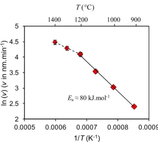
For Qtot = 360 sccm, the growth rate increases with the temperature in the range of 900-1400 °C (Tab. 1). Two slopes are visible on the Arrhenius plot shown in Fig. 3, with a transition occurring at about 1200 °C. This feature can be attributed to a change in the global deposition mechanism.
The first domain below 1200 °C should correspond to a reaction-limited regime, with an apparent activation energy Ea equal to 80 kJ.mol-1. As a comparison, Cheng et al. [33] found a value of 125 kJ.mol-1 in the range of 650-1000 °C, whereas Ye et al. [34] obtained 113 kJ.mol-1 in the range of 650-800 °C using the same gas system (BCl3−NH3−H2). The lower apparent activation energy may arise from the different deposition parameters used here, such as the pressure and dilution ratio. Indeed, the pressure chosen in the present work was lower than the pressure of 1 kPa used by Cheng et al. and β was five times higher. In the study of Ye et al. the pressure was lower than 1 kPa but the dilution ratio was not given, making the comparison difficult. Given that these parameters can have a significant effect on CVD kinetics, such differences could account for the discrepancies in Ea values.
The decrease of Ea to 40 kJ.mol-1 observed above 1200 °C should correspond to a mass transport-limited regime, at least in part, because the effect of temperature on the growth rate becomes less important. The influence of the total gas flow rate at 1200 °C evidences that this temperature corresponds to a transition between both regimes. The activation energy of 11 kJ.mol-1 measured by Ye et al. [34] in the range of 800-1000 °C was attributed to a mass transport limited regime. These authors also reported that the growth rate decreases because of gas phase nucleation occurring above 1000 °C. In the present work, the decrease of Ea is obtained only in the range of 1200-1400 °C. This suggests that the possible gas phase nucleation and the resulting precursor depletion are expected to occur at much higher temperature than for the study of Ye et al.
5
4.1.2. Surface morphology of the coatings from BCl3−NH3−H2 gas mixtures
With Qtot = 360 sccm, the surface roughness of the coatings increases for deposition temperatures above 1200 °C (Fig. 4). This change in surface morphology is in line with the change in deposition regime identified above. At 900 °C, white nodules appear on the coating surface in the SEM images after a 24-h exposure to ambient air. The poor chemical stability of BN films deposited from BCl3 and NH3 at low temperature in the presence of moisture has been reported by several authors [35] [36]. The hydrolysis of BN by moisture leads to the formation of ammonium borate hydrate crystals whose appearance corresponds to the particles observed here. This instability may originate from unreacted BN gaseous precursors (NH3 and BCl3) that are trapped within the coating and react with H2O. For deposition temperatures above 900 °C, these nodules are no more detected indicating a better coating stability.
4.1.3. Chemical and crystal structure of the coatings from BCl3−NH3−H2 gas mixtures
At a deposition temperature of 1200 °C, the degree of crystallization and η both decrease as the total gas flow rate increases (Fig. 5.a) (Tab. 1). Keeping in mind that when the η ratio is well below 1 the asymmetry of the BN XRD peak is high, these results show not only that the coating exhibits a poor structural homogeneity, but that it becomes even worse as the gas residence time is decreased.
With Qtot = 360 sccm, the degree of crystallization increases with the deposition temperature (Fig. 5.b). At high temperature (T > 1200 °C), the coatings exhibit an interreticular distance d as low as 0.336 (± 0.001) nm and a coherence length Lc as high as 12.0 (± 0.1) nm. These values approximate d = 0.334 (± 0.001) nm and Lc = 11.8 (± 0.1) nm, obtained from a commercial boron nitride supplied by Advanced Ceramics, also processed by CVD from BCl3−NH3−H2 gas mixtures but at a temperature of about 2000 °C. Conversely, the structural homogeneity decreases when the deposition temperature increases (Tab. 1). At high temperature, the coatings are clearly made of a mixture of highly and poorly crystallized sp2-BN. A similar feature has already been observed by Matsuda et al. [37] and Chubarov et al. [38]; it was likely enhanced by the use of cold-wall CVD reactors restricting the gas phase maturation and by higher substrate temperatures. Several other authors have also mentioned XRD BN asymmetric peaks in their papers, but this feature is not further discussed [33] [35].
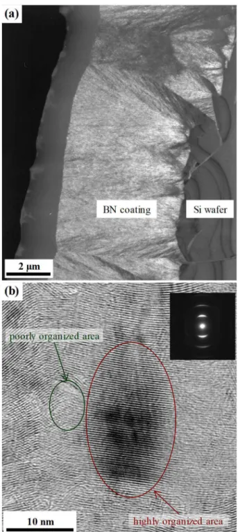
The dark field TEM images reveal only little contrast and show small cones that regenerate all along the growth and do not develop across the entire thickness of the coating deposited at 1200 °C and with Qtot = 360 sccm (Fig. 6.a). The SAD patterns are typical, with their arcs, of a turbostratic material with overall structural anisotropy. HRTEM observations show a mixture of small and large coherent domains into the coating. In the smaller domains the fringes are disordered and poorly developed, while the larger domains contain well-developed parallel fringes corresponding to the basal planes of sp2-BN (Fig. 6.b). These HRTEM observations evidence that the structural inhomogeneity occurs on a very local scale.
The average binding energies and proportions of the various B1s components evidenced by XPS, for BN films processed with the same deposition parameters, mainly show the presence of sp2 B-N bonds for the most part as well as a few B-NO bonds, while the presence of B-C and B-B bonds is
6
respectively hardly and not detected (Tab. 2). Chlorine is never evidenced (< 1%at.). This indicates that nearly pure BN was deposited, even though a slight reaction between the coating surface and moisture has occurred during the air exposure of the samples.
In order to better understand the influence of the precursor gas mixture on the crystal structure of the coatings, an experiment has been carried out by switching the gas entry points in the reactor. NH3 was fed into the reactor with H2 at room temperature, far upstream from the deposition reactor area, whereas BCl3 was injected on its own, closer to the deposition area, at about 700 °C. The coating deposited with switched gas entries exhibits a higher crystallization degree (d = 0.338 (± 0.001) nm and Lc = 8.7 (± 0.1) nm) and a better structural homogeneity (η = 0.6) than the sample obtained in standard configuration (d = 0.339 (± 0.001) nm, Lc = 5.9 (± 0.1) nm and η = 0.5) (Fig. 7). Hence, when H2 is used as the diluent gas, the degree of crystallization and the structural homogeneity of the coatings both vary significantly with the gas entry configuration.
4.1.4. Comparison with deposition from BCl3−NH3−Ar gas mixtures
A coating was deposited using argon as the diluent (or carrier) gas instead of hydrogen, all the other parameters remaining unchanged (α, β, Qtot and T). As shown in Fig. 8, the diffraction peak is a little narrower and more symmetrical. The coating deposited with Ar exhibits a higher degree of crystallization and a better structural homogeneity (d = 0.336 (± 0.001) nm, Lc = 11.5 (± 0.1) nm and η = 0.8) than the specimen deposited with H2. One should note besides that the growth rate is slightly reduced (3.2 (± 0.1) µm/h with Ar instead of 3.5 (±0.1) µm/h with H2).
Similar crystallographic parameters are obtained using argon dilution deposition when Qtot is reduced by half. Thus, the total flow rate has no significant effect on the degree of the crystallization and the structural homogeneity of the coatings deposited from BCl3−NH3−Ar gas mixtures.
4.2. Gas phase analysis
As the analysis was carried out ex situ at room temperature, the detected molecules are necessarily stable and some of them may result from the recombination of unstable intermediates (e.g. BCl2 and BCl radicals). However, the consumption of BCl3 and NH3, the apparition of new species at the reactor outlet and their possible consumption due to homogeneous or heterogeneous reactions as a function of conditions provide useful information for a better understanding of the CVD process.
From preliminary tests carried out using the BCl3-free system, it has been found that the ammonia proportion detected by FTIR at the reactor outlet decreases with T, it is of 65% after passage through the reactor heated at T = 1200°C with respect to the quantity of introduced NH3. For each temperature studied in this work, the proportion of NH3 at the reactor outlet is the same either with hydrogen or argon dilution. Thus, the kinetic of the thermal decomposition of ammonia can be considered as independent of the nature of these diluent gases.
7 4.2.1. NH3-free system
To better understand the possible reactions between BCl3 and hydrogen, ex situ FTIR analyses have been first performed with the BCl3−H2 and BCl3−Ar systems.
An experiment has been carried out without ammonia and with a reduced gas flow rate (Qtot = 200 sccm), in order to replicate the reactor inlet conditions encountered upstream from the NH3 injection point (at about 700 °C), when the reactor is run in BN deposition conditions.
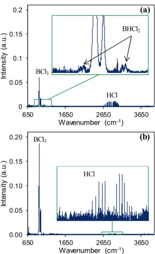
BHCl2 was previously detected by FTIR by Reinisch et al. in a similar experiment using the BCl3−H2 system at a temperature of 500 °C and a pressure of 1 kPa [25]. Here, from the same BCl3−H2 gas mixture, BHCl2 is only detected above 650 °C, i.e. only 50 °C below the NH3 injection temperature (Fig. 9.a). However, as shown in Fig. 9.b, HCl bands are visible on the spectrum obtained at a temperature as low as 500 °C, while boron deposition is unlikely to occur below 750 °C [39]. The only homogeneous reaction that is likely to produce hydrogen chloride is BCl3 (g) + H2 (g) BHCl2 (g) + HCl (g). Therefore, in the conditions used in this experiment, the BHCl2 formation is expected to start at a temperature as low as 500 °C. Thus, this reaction must be considered for the boron nitride deposition from the full gas system. It should be noted that as expected, HCl is not detected from BCl3−Ar gas mixtures.
4.2.2. Full gas system
With the full gas system, i.e. under the experimental conditions previously used for BN deposition (Qtot = 360 sccm and T = 1200 °C), several new peaks are observed on the FTIR spectrum. In addition to unreacted BCl3, CO2 and HCl are detected as well as an NH4Cl condensate deposited on the cold surfaces at temperatures below 300 °C, including the ZnSe windows of the analysis cell. The presence of CO2 can be explained by the presence of residual air along the IR beam path, despite the nitrogen purge. The calculations of the IR relative intensities and vibrational frequencies of species took from literature [31] led to the assignment of aminodichloroborane (Cl2BNH2) (Tab. 3) on the experimental FTIR spectrum (Fig. 10). Cl2BNH2 was already detected by mass spectroscopy by Pavlovic et al. [18] and McDaniel and Allendorf [24]. An infrared spectrum of Cl2BNH2 in the condensed state produced from the reaction between BCI3 and NH3 was also published by Kwon and McGee [40]. The band positions for monomeric aminodichloroborane were then specified by calculation by Reinhardt et al. [41] and are in good agreement with ours. It is worth noting, however, that the IR spectrum of this species in the gaseous state was not available in open databases so far. No other species containing boron or nitrogen were detected from the full gas system at the outlet of our reactor. NH3 is obviously depleted by the BN deposition and NH4Cl formation. Whatever the diluent gas (H2 or Ar), similar vibrational modes are observed on the FTIR spectrum. From all the IR features, only one peak ( 1080 cm-1) could not be assigned to any known species.
According to the plot shown in Fig. 11.a, the areas of the BCl3 and Cl2BNH2 characteristic peaks decrease as the temperature increases (the reference BCl3 peak area measured at room temperature is 4.12 (± 0.01) a.u.). Meanwhile, no further species is detected, while the growth rate increases as observed previously. Cl2BNH2 can thus be considered either as an intermediate species or as an effective precursor involved in the boron nitride deposition. A change in the slope of the Cl2BNH2 concentration curve is observed at 1200 °C (Fig. 11.a). This feature is related to the change in the deposition regime,
8
as observed previously from the Arrhenius plot. The production and depletion of aminodichloroborane occurring successively as the temperature is raised, seem then to control the overall boron nitride deposition mechanism.
As can be seen in Fig. 11.b, the Cl2BNH2 concentration increases with Qtot and reaches a maximum value for a total flow rate close to 250 sccm. The BCl3 concentration increases together with the Cl2BNH2 concentration up to a total gas flow rate of 250 sccm. It then decreases above 250 sccm, no new species being detected besides. These results are consistent with the change in the BN growth rate. They can be explained by a homogeneous nucleation phenomenon starting at high gas flow rates.
As mentioned earlier, the same IR vibrational modes were detected with both H2 and Ar, indicating that similar species were formed in the reactor with either of the two diluent gases. In contrast, the relative intensities of the Cl2BNH2 and BCl3 characteristic peaks are different. Indeed, as can be noticed in Tab. 4, [BCl3]Ar > [BCl3]H2, whereas [Cl2BNH2]Ar ≤ [Cl2BNH2]H2. Such a difference in the residual concentration of BCl3 is consistent, given that the use of hydrogen instead of argon leads to a higher precursor consumption (through BCl3 reduction) and hence, a higher BN growth rate. The NH3 decomposition rate does not depend on the nature of the diluent gas. In contrast, the higher residual Cl2BNH2 concentration measured when replacing argon by hydrogen, while the deposition kinetics is still rather high, could be due to the existence of another boron bearing species (likely BHCl2) acting as effective precursor of the BN deposit.
5. Discussion
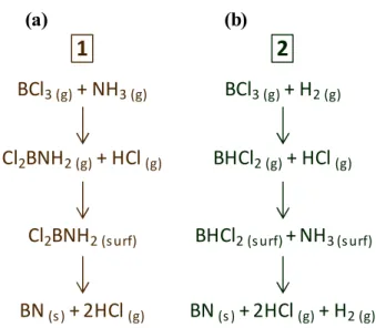
The results shown in section 4.2 and obtained from FTIR measurements confirm that Cl2BNH2 is key gas-phase precursor to BN as reported in the work of Allendorf et al. [23] and later in that of McDaniel and Allendorf [24]. As in the latter study, ClBNH was never detected at the outlet of our reactor, although its production from Cl2BNH2 (losing HCl) can be expected at high temperatures in the B−N−Cl−H system [42] or from the BCl3–NH3–H2 system [43]. The very short gas resident time in our reactor, due to the very low pressure, does not seem to allow the decomposition of Cl2BNH2 into ClBNH. Therefore, Cl2BNH2 can adsorb on the hot substrate surface and form BN after releasing two HCl molecules in the gas phase. This route seems to be involved in the deposition of boron nitride whatever the nature of the diluent or carrier gas and lead to the simplified reaction path N°1 presented in Fig. 12.a. Even if not detected from the full original BCl3−NH3−H2 system, BHCl2 is formed from the reaction between BCl3 and H2 upstream from the ammonia inlet (i.e. at temperatures in the range 500-700 °C). BHCl2 is then an additional boron containing species that can react with NH3 (or derived radical species) to form BN. The thermodynamic study conducted by Ren et al. from this system suggests that BHCl2 is a crucial intermediate with, to a lesser extent, BCl, BClNH and BH2Cl [43]. The formation of the last three species could not be detected here by FTIR because of their instability or their too low concentrations. However, when the quantity of reagents introduced at the reactor inlet is sufficient, the formation of BHCl2 can lead to the simplified reaction path N°2 presented in Fig. 12.b. BN can then be deposited according to two possible reaction paths from the BCl3−NH3−H2 system, whereas only one route is allowed from the BCl3−NH3−Ar system. In the former case, the addition of path N°2 to N°1 allows a higher growth rate.
The BN obtained using H2 is less organized and homogeneous than the ex-Ar BN. The difference in microstructure can be related to the different highlighted growth mechanisms. When both
9
paths are involved (i.e. with H2 as the diluent gas and high enough total gas flow rates), the resulting coatings are therefore made of a mixture of poorly and highly crystallized boron nitride. With a total gas flow rate that is 4 times smaller than that used in standard conditions, the crystallization degree and the structural homogeneity are both improved. This phenomenon is attributed to BHCl2 depletion between the NH3 entry point and the hot deposition area, leading to the disappearance of reaction path N°2 in favour of reaction path N°1. The absence of BHCl2 at the reactor outlet indicates that its consumption through BN deposition can be fast and total even when the high standard total gas flow rate is applied. The results obtained by switching the gas entrances confirm the role of BHCl2 in the disorganization of the material structure and the deposition rate level. Indeed, with hydrogen dilution, keeping as long as possible BCl3 separated from H2 prevents the pre-reaction leading to BHCl2. The resulting kinetics and structure are then similar to those obtained with argon dilution. The hypothesis that can be drawn is that the reaction path N°1 involving Cl2BNH2 leads to highly crystallized BN whereas reaction path N°2 with BHCl2 produces poorly organized coatings.
The reduction of the degree of crystallization observed when H2 is the diluent gas and with the CVD device in standard configuration may originate from the growth of quasi-amorphous free boron. These boron clusters could impede the growth of the highly organized domains like in the case of boron-rich pyrocarbon materials [44]. For the BN deposition from BCl3−NH3−H2 and in conditions similar to ours, the deposit was found to be a mixture of hexagonal BN and elemental boron when α ≤ 1 [22] [45]. But, as in the present work α was always greater than one and B-B bonds were not detected by XPS, BHCl2 is unlikely to lead to such boron-rich parts. Instead, the poorly crystallized domains resulting from reaction path N°2 have a boron-to-nitrogen ratio close to one. A most likely hypothesis would be the incorporation of hydrogen in the coating interfering with its structural organization. Hydrogen is indeed a by-product of the last reaction occurring at the substrate surface according to path N°2. A parallel can be drawn with laminar pyrocarbon deposition. It has been shown from elastic recoil detection analysis (ERDA) that the microtexture of pyrocarbon and the residual hydrogen trapped in the coating (which is dependent on homogeneous and heterogeneous dehydrogenations) are both correlated [46] [47] [48]. The measurement of the hydrogen content in the different BN coatings should be useful, in a further work, for verifying this hypothesis. For BN infiltration purpose, it would be also interesting to study the effects of the internal surface area using different porous substrates. This parameter was indeed found to be very influent on the deposition chemistry for other chemical systems [49]. Since BCl3−NH3−H2 mixtures were shown to be unsuitable for the deposition of well crystallized hexagonal BN within porous substrates [22], such a study should be performed with another carrier gas than hydrogen.
6. Conclusion
The effects of the deposition temperature and total gas flow rate on the microstructure of BN coatings deposited from BCl3−NH3−H2 at low pressure have been studied. For two given deposition parameter sets, a comparison with the BCl3−NH3−Ar system has shown that the coatings deposited with Ar exhibit a higher crystallization degree and a better structural homogeneity than those deposited with H2. Ex situ FTIR analyses of the exhaust gases, coupled with ab initio vibrational mode calculations, have allowed assigning particular peaks of the spectrum to vibrational bands to aminodichloroborane (Cl2BNH2). The changes in the Cl2BNH2 concentration in the residual gases as a function of deposition temperature, the gas flow rate and the growth kinetics, have shown that this species can be considered either as an
10
intermediate or an effective precursor of highly crystallized BN domains, whether H2 or Ar is used as a carrier gas. The BCl3−H2 gas mixture has also been studied by FTIR. BHCl2 is formed even at temperature as low as 500 °C. BHCl2 seems to be another intermediate species, which can react with NH3 to produce BN. The resulting material consists of poorly organized domains disorganizing the overall material structure. BN interphases with a high degree of crystallinity combined with a good structural homogeneity may be favourable to the oxidation resistance of CMCs during their use in severe environments. One way to deposit such interphases from the conventional BCl3-NH3 system is to avoid either the use of H2 or the direct reaction between H2 and BCl3 by optimizing the injection of the different gases into the CVD reactor.
Acknowledgements
This work was supported by SAFRAN CERAMICS through a grant given to P. Carminati. The authors would like to thank L. Lapuyade from LCTS and C. Labrugère from PLACAMAT (UMS 3626 CNRS-Bordeaux University), for XPS analysis and data treatment. The authors are indebted to B. Cossou who participated to the deposition of some BN coatings. Finally, the authors wish to pay tribute to the late E. Buet and express their gratitude to his colleague A. Delcamp from SAFRAN CERAMICS for fruitful discussions.
References
[1] J. Eichler, C. Lesniak, Boron nitride (BN) and BN composites for high-temperature applications, Journal of the European Ceramic Society 28 (2008) 1105–1109.
http://dx.doi.org/10.1016/j.jeurceramsoc.2007.09.005
[2] C. G. Cofer, J. Economy, Oxydation and hydrolitic stability of boron nitride. A new approach to improving the oxidation resistance of carbonaceous structures, Carbon 33 (1995), 389–395.
http://dx.doi.org/10.1016/0008-6223(94)00163-T
[3] X. Fan, X. Yin, Y. Cheng, L. Zhang, L. Cheng, Microstructure and tribological behaviors of C/C– BN composites fabricated by chemical vapor infiltration, Ceramics International 38 (2012) 6137– 6144. http://dx.doi.org/10.1016/j.ceramint.2012.04.063
[4] A. G. Evans, F. W. Zok, T. J. Mackin, The Structural Performance of Ceramic Matrix Composites, in: S.V. Nair, K. Jakus (Eds.), High Temperature Mechanical Behavior of Ceramic Composites, ch. 1, Butterworth-Heinemann Elsevier Ltd, Oxford, United Kingdom, 1995, pp. 3–84.
https://doi.org/10.1016/B978-075069399-8/50002-5
[5] R. Naslain, The design of the fibre-matrix interfacial zone in ceramic matrix composites, Composites Part A: Applied Science and Manufacturing 29 (1998) 1145–1155.
11
[6] S. Jacques, A. Lopez-Marure, C. Vincent, H. Vincent, J. Bouix, SiC/SiC minicomposites with structure-graded BN interphases, Journal of the European Ceramic Society 20 (2000) 1929–1938.
http://dx.doi.org/10.1016/S0955-2219(00)00064-9
[7] G. N. Morscher, H.M. Yun, J.A. DiCarlo, L.T. Ogbuji, Effect of a boron nitride interphase that debonds between the interphase and the matrix in SiC/SiC composites, Journal of the American Ceramic Society 87 (2004) 104–112. http://dx.doi.org/10.1111/j.1551-2916.2004.00104.x
[8] A. Udayakumar, A. Sri Ganesh, S. Raja, M. Balasubramanian, Effect of intermediate heat treatment on mechanical properties of SiCf/SiC composites with BN interphase prepared by ICVI, Journal of
the European Ceramic Society 31 (2011) 1145–1153.
http://dx.doi.org/10.1016/j.jeurceramsoc.2010.12.018
[9] N Sun, C Wang, L Jiao, J Zhang, Di Zhang, Controllable coating of boron nitride on ceramic fibers by CVD at low temperature, Ceramics International 43 (2017) 1509–1516
http://dx.doi.org/10.1016/j.ceramint.2016.10.123
[10] S. Prouhet, A. Guette, F. Langlais, An experimental kinetic study of boron nitride CVD from BF3 -NH3-Ar mixtures, Journal de Physique IV 02 (1991) 119–126. http://dx.doi.org/10.1051/jp4:1991214 [11] F. Rebillat, A. Guette, R. Naslain, C. Robin Brosse, Highly ordered pyrolytic BN obtained by
LPCVD, Journal of the European Ceramic Society 17 (1997) 1403–1414.
http://dx.doi.org/10.1016/S0955-2219(96)00244-0
[12] Jacques, A. Lopez-Marure, C. Vincent, H. Vincent, J. Bouix, Multilayered BN Coatings Processed by a Continuous LPCVD Treatment onto Hi-Nicalon Fibers, Journal of Solid State Chemistry 162 (2001) 358–363. doi:10.1006/jssc.2001.9387
[13] J. S. Li, C. R. Zhang, B. Li, F. Cao, S. Q. Wang, Boron nitride coatings by chemical vapor deposition from borazine, Surface and Coatings Technology 205 (2011) 3736–3741
http://dx.doi.org/10.1016/j.surfcoat.2011.01.032
[14] R. Stolle, G. Wahl, Deposition of Boron Nitride Films from BB'B"-Trichloroborazine, Journal de Physique IV 05 (1995) 761–768. http://dx.doi.org/10.1051/jphyscol:1995590
[15] S. Jacques, B. Bonnetot, M. P. Berthet, H. Vincent, BN Interphase Processed by LP-CVD from Tris(Dimethylamino)Borane and Characterized using SiC/SiC Minicomposites, in 28th International Conference on Advanced Ceramics and Composites B: Ceramic Engineering and Science Proceedings Volume 25, Issue 4 (2004) pp. 123–128 (eds E. Lara-Curzio and M. J. Readey), John Wiley & Sons, Inc., Hoboken, NJ, USA http://dx.doi.org/10.1002/9780470291191.ch20
[16] C. Lorette, P. Weisbecker, S. Jacques, R. Pailler, J-M. Goyhénèche, Deposition and characterization of hex-BN coating on carbon fibres using tris(dimethylamino)borane precursor, Journal of the European Ceramic Society 27 (2007) 2737–2743.
http://dx.doi.org/10.1016/j.jeurceramsoc.2006.10.010
[17] H. Wu, M. Chen, X. Wei, M. Ge, W. Zhang, Deposition of BN interphase coatings from B-trichloroborazine and its effects on the mechanical properties of SiC/SiC composites, Applied Surface Science 257 (2010) 1276–1281. http://dx.doi.org/10.1016/j.apsusc.2010.08.047
12
[18] V. Pavlovic, H. Kötter, C. Meixner, Chemical vapor deposition of boron nitride using premixed borontrichloride and ammonia, Journal of Material Research 6 (1991) 2393–2396.
https://doi.org/10.1557/JMR.1991.2393
[19] N. Patibandla, K. L. Luthra, Chemical Vapor Deposition of Boron Nitride, Journal of the Electrochemical Society 139 (1992) 3558–3565. http://dx.doi.org/10.1149/1.2069121
[20] T. Matsuda, H. Nakae, T. Hirai, Density and deposition rate of chemical-vapour-deposited boron nitride, Journal of Materials Science 23 (1988) 509–514. http://dx.doi.org/10.1007/BF01174677
[21] V. Cholet, L. Vandenbulcke, Chemical Vapor Infiltration of Boron Nitride Interphase in Ceramic Fiber Preforms: Discussion of Some Aspects of the Fundamentals of the Isothermal Chemical Vapor Infiltration Process, Journal of the American Ceramic Society 76 (1993) 2846–2858
http://dx.doi.org/10.1111/j.1151-2916.1993.tb04026.x.
[22] H. Hannache, R. Naslain, C. Bernard, Boron nitride chemical vapour infiltration of fibrous materials from BCl3-NH3-H2 or BF3-NH3 mixtures: A thermodynamic and experimental approach,
Journal of the Less Common Metals 95 (1983) 221–246.
http://dx.doi.org/10.1016/0022-5088(83)90517-9
[23] M. D. Allendorf, C. F. Melius, T. H. Osterheld, A Model of the Gas-Phase Chemistry of Boron Nitride CVD from BCl3 and NH3, in Covalent Ceramics III- Science and Technology of Non-Oxides, Hepp, A. F., Kumta, P. N., Sullivan, J. J., Fischman, G. S., Kaloyeros, A. E., Eds.; Materials Research Society Symposium Proceedings 410; Boston, MA, 1996, pp. 459–464.
http://dx.doi.org/10.1557/PROC-410-459
[24] A. H. McDaniel, M. D. Allendorf, Flow-Tube Investigation of the High-Temperature Reaction between BCl3 and NH3, Journal of Physical Chemistry A 102 (1998) 7804–7812. http://dx.doi.org/10.1021/jp981846g
[25] G. Reinisch, J.-M. Leyssale, N. Bertrand, G. Chollon, F. Langlais, G. Vignoles, Experimental and theoretical investigation of BCl3 decomposition in H2, Surface and Coatings Technology 203 (2008) 643–647. http://dx.doi.org/10.1016/j.surfcoat.2008.04.086
[26] O. Ledain, W. Woelffel, J. Roger, G. Vignoles, L. Maillé, S. Jacques, Reactive Chemical Vapour Deposition of titanium carbide from H2-TiCl4 gas mixture on pyrocarbon: a comprehensive study, Physics Procedia 46 (2013) 79–87. http://dx.doi.org/10.1016/j.phpro.2013.07.048
[27] P. Drieux, G. Chollon, S. Jacques, A. Allemand, D. Cavagnat, T. Buffeteau, Experimental study of the chemical vapor deposition from CH3SiHCl2/H2: Application to the synthesis of monolithic SiC tubes, Surface and Coatings Technology 230 (2013) 137–144.
http://dx.doi.org/10.1016/j.surfcoat.2013.06.046
[28] M. Chubarov, H. Högberg, A. Henry, H. Pedersen, Review Article: Challenge in determining the crystal structure of epitaxial 0001 oriented sp2-BN films, Journal of Vacuum Science & Technology A 36 (2018) 030801 (5 pp.). https://doi.org/10.1116/1.5024314
[29] M. J. Frisch, G. W. Trucks, H. B. Schlegel, G. E. Scuseria, M. A. Robb, J. R. Cheeseman, G. Scalmani, V. Barone, B. Mennucci, G. A. Petersson, H. Nakatsuji, M. Caricato, X. Li, H. P. Hratchian, A. F. Izmaylov, J. Bloino, G. Zheng, J. L. Sonnenberg, M. Hada, D. Fox, Douglas, Gaussian 09, revision A.1, Gaussian Inc., Wallingford CT (2009).
13
[30] C. Lee, W. Yang, R. G. Parr, Development of the Colle-Salvetti correlation-energy formula into a functional of the electron density, Physical Review B 37 (1988) 785–789.
http://doi.org/10.1103/PhysRevB.37.785
[31] A. D. Becke, Density‐functional thermochemistry. III. The role of exact exchange, Journal of Chemical Physics 98 (1993) 5648–5652. https://doi.org/10.1063/1.464913
[32] M. H. Jamroz, Vibrational Energy Distribution Analysis VEDA 4, Warsaw, 2004-2010.
http://www.smmg.pl/
[33] Y. Cheng, X. Yin, Y. Liu, L. Zhang, BN coatings prepared by low pressure chemical vapor deposition using boron trichloride–ammonia–hydrogen–argon mixture gases, Surface and Coatings Technology 204 (2010) 2797–2802. http://dx.doi.org/10.1016/j.surfcoat.2010.02.046
[34] F. Ye, L. Zhang, Y. Liu, M. Su, L. Cheng, X. Yin, Investigation of boron nitride prepared by Low Pressure Chemical Vapor Deposition at 650~1200 °C, Key Engineering Materials 537 (2013) 58– 62. http://dx.doi.org/10.4028/www.scientific.net/KEM.537.58
[35] S. Le Gallet, G. Chollon, F. Rebillat, A. Guette, X. Bourrat, R. Naslain, M. Couzi, J. L. Bruneel, Microstructural and microtextural investigations of boron nitride deposited from BCl3–NH3–H2 gas mixtures, Journal of the European Ceramic Society 24 (2004) 33–44.
http://dx.doi.org/10.1016/S0955-2219(03)00126-2
[36] V. Cholet, L. Vandenbulcke, J. P. Rouan, P. Baillif, R. Erre, Characterization of boron nitride films deposited from BCl3-NH3-H2 mixtures in chemical vapour infiltration conditions, Journal of Materials Science 29 (1994) 1417–1435. http://dx.doi.org/10.1007/BF00368905
[37] T. Matsuda, N. Uno, H. Nakae, T. Hirai, Synthesis and structure of chemically vapour-deposited boron nitride, Journal of Materials Science 21 (1986) 649–658.
http://dx.doi.org/10.1007/BF01145537
[38] M. Chubarov, H. Pedersen, H. Högberg, Zs. Czigany and A. Henry, Chemical vapour deposition of epitaxial rhombohedral BN thin films on SiC substrates, CrystEngComm 16 (2014) 5430–5436.
http://dx.doi.org/10.1039/C4CE00381K
[39] N. A. Sezgi, T. Dogu, H. Ö. Özbelge, BHCl2 Formation during Chemical Vapor Deposition of Boron in a Dual-Impinging Jet Reactor, Industrial & Engineering Chemistry Research 36 (1997) 5537–5540. http://dx.doi.org/10.1021/ie970225r
[40] C. T. Kwon and H. A. McGee Jr., Aminodichloroborane, Inorganic Chemistry 12 (1973) 696–697
http://dx.doi.org/10.1021/ic50121a045
[41] S. Reinhardt, M. Gastreich, C. M. Marian, Simulation of the Solid State Vibrational Spectra of Aminodichloroborane and Ammonia Boron Trichloride, Zeitschrift für anorganische und allgemeine Chemie 626 (2000) 1871–1880. http://dx.doi.org/10.1002/1521-3749(200009)626:9<1871::AID-ZAAC1871>3.0.CO;2-W
[42] M. D. Allendorf, C. F. Melius, Thermochemistry of Molecules in the B−N−Cl−H System: Ab Initio Predictions Using the BAC-MP4 Method, Journal of Physical Chemistry A 101 (1997) 2670–2680.
14
[43] H. Ren, Li. Zhang, K. Su, Q. Zeng, L. Cheng, Thermodynamic study on the chemical vapor deposition of boron nitride from the BCl3–NH3–H2 system, Theoretical Chemistry Accounts, 133 (2014), 1583 (13 pp.) https://doi.org/10.1007/s00214-014-1583-5
[44] S. Jacques, A. Guette, X. Bourrat, F. Langlais, C. Guimon, C. Labrugere, LPCVD and characterization of boron-containing pyrocarbon materials, Carbon 34 (1996) 1135–1143.
doi:10.1016/0008-6223(96)00075-9
[45] J-L. Huang, C-H. Pan and D-F. Lii, Investigation of the BN films prepared by low pressure chemical vapor deposition, Surface and Coatings Technology 122 (1999) 166–175.
http://dx.doi.org/10.1016/S0257-8972(99)00306-0
[46] J. Lavenac, F. Langlais, X. Bourrat, R. Naslain, Deposition process of laminar pyrocarbon from propane, Thirteenth European Conference on Chemical Vapor Deposition 11 (2001) 1013–1021.
http://dx.doi.org/10.1051/jp4:20013127
[47] F. Langlais, H. Le Poche, J. Lavenac, O. Féron, Multiple experimental investigations for understanding CVD mechanism: example of laminar pyrocarbon deposition, In A. Devi, R. Fischer, H. Parala, M. Hitchman, M. Allendorf (Eds.), Proceeding EuroCVD-15 (2005) pp. 73–86 (Electrochemical Society Proceedings; Vol. 2005-09). Pennington, New Jersey, USA: Electro Chemical Society, ISBN (Print) 1-56677-427-6
[48] P. Weisbecker, J-M. Leyssale, H. E. Fischer, V. Honkimäki, M. Lalanne, G. L. Vignoles, Microstructure of pyrocarbons from pair distribution function analysis using neutron diffraction, Carbon 50 (2012) 1563–1573. http://dx.doi.org/10.1016/j.carbon.2011.11.035
[49] K. J. Hüttinger, W. Benzinger, Chemistry and kinetics of chemical vapor infiltration of pyrocarbon – VI. Mechanical and structural properties of infiltrated carbon fiber felt, Carbon 37 (1999) 1311– 1322. http://dx.doi.org/10.1016/S0008-6223(98)00327-3
15
Tables
Table 1. Growth rates (± 0.1 µm/h) and η factor values for BN coatings deposited from BCl3−NH3−H2 gas mixtures at different temperatures T and for different total gas flow rates Qtot.
Qtot (sccm) 100 200 242 300 360 360 360 360 360 360 T (°C) 1200 1200 1200 1200 900 1000 1100 1200 1300 1400 Growth rate
(µm/h) 1.4 2.9 3.1 3.5 0.7 1.3 2.1 3.5 4.4 5.3
η 0.6 0.5 0.5 0.5 0.7 0.5 0.5 0.4 0.3 0.3
Table 2. Average binding energies and proportions of B 1s components measured by XPS for BN films deposited from BCl3−NH3−H2 gas mixtures with Qtot = 360 sccm and at 1200 °C
Component Energy (eV) %
B-N 190.8 79
B-NO 191.9 13
B-CO 189.7 6
B-C 188.6 2
Table 3. IR vibrational modes and relative intensities calculated for Cl2BNH2. δ and ν refer to as bending and stretching vibrations, respectively and the subscripts a and s refer to as asymmetric and symmetric modes, respectively Mode νa(NH2) νs(NH2) 90%δ(NH+ 10%ν(BN) 2) 77%ν(BN) + 10%δ(NH2) + 13%νs(BCl2) 75%δ(BNH) + 25%δ(NBCl) 73%νa(BCl2) + 27%δ(BNH) 86%νs(BCl2) + 14%ν(BN) Position (cm-1) 3697 3596 1624.4 1347.6 1073.3 768.5 549.3 Relative intensity (a.u.) 42 60 169 166 274 98 17
Table 4. FTIR peak areas for residual BCl3 and Cl2BNH2 from BCl3−NH3−H2 and BCl3−NH3−Ar gas mixtures (T = 1200 °C, Qtot = 200 sccm)
Diluent gas BCl3 peak area (a.u.) Unreacted BCl3 (%) Cl2BNH2 peak area (a.u.)
H2 0.13 (± 0.01) 3 0.17 (± 0.01)
16
Figures
Figure 1 – LPCVD reactor in standard configuration and FTIR gas phase analysis apparatus N2 liq pump traps
an
aly
sis
c
ol
um
n
(R
T)
pressure controller0
deposition area NH3 BCl3 + H2or Ar NH3entry point @ ~700°C BCl3 entry point @ RT graphite tube induction coilLPCVD
reactor
1 I=f(n)FTIR
spectrometer
HgCdTe detector substrates insolation17
Figure 2 - Typical asymmetry of the XRD peak related to the diffraction from adjacent basal planes of deposited sp2 -BN
Figure 3 - Arrhenius plot for BN deposited from BCl3−NH3−H2 gas mixtures with Qtot = 360 sccm 0 50 100 150 200 250 300 350 20 25 30 In te ns ity (c ou nt s/ s) 2θ (°) 2θImax 2 2.5 3 3.5 4 4.5 5 0.0005 0.0006 0.0007 0.0008 0.0009 ln (v ) ( v in n m .m in -1) 1/T (K-1) 1400 1200 1000 900 Ea≈ 80 kJ.mol-1 T (°C)
18
Figure 4 - SEM surface observation of coatings deposited from BCl3−NH3−H2 gas mixtures with Qtot = 360 sccm (a) at 900 °C, (b) at 1000 °C, (c) at 1100 °C, (d) at 1200 °C, (e) at 1300 °C and (f) at 1400 °C
19
Figure 5 - Crystal structure data Lc and d obtained from XRD Bragg peak related to the diffraction from adjacent basal planes of BN films deposited from BCl3−NH3−H2 gas mixtures at 1200 °C vs Qtot (a) and with Qtot = 360 sccm vs.
temperature (b) 0.334 0.336 0.338 0.340 0.342 0.344 0.346 2 4 6 8 10 12 0 100 200 300 400 d (n m ) Lc (n m ) Qtot(sccm) 0.334 0.336 0.338 0.340 0.342 0.344 0.346 2 4 6 8 10 12 800 900 1000 1100 1200 1300 1400 1500 d (n m ) Lc (n m ) Temperature (°C) (a) (b)
20
Figure 6 - TEM observations of coating deposited from BCl3−NH3−H2 gas mixture (Qtot = 360 sccm and T = 1200 °C). Dark-field image through the entire thickness of the coating (a), HRTEM image of the middle of the coating and SAD
21
Figure 7 - XRD patterns of BN coatings deposited with Qtot = 360 sccm and T = 1200 °C from BCl3−NH3−H2 gas mixtures with standard or switched gas entry points
Figure 8 - XRD patterns of BN films deposited from BCl3−NH3−H2 and BCl3−NH3−Ar gas mixtures with Qtot = 360 sccm and at 1200 °C 0 50 100 150 200 20 25 30 In te ns ity (c ou nt s/ s) 2θ (°) standard configuration switched entries 0 50 100 150 200 250 300 350 20 25 30 In te ns ity (c ou nt s/ s) 2θ (°) Ar H2
22
Figure 9 - FTIR spectra from BCl3−H2 gas mixtures with Qtot = 200 sccm, at 800 °C (a) and 500 °C (b)
Figure 10 - FTIR spectrum from BCl3−NH3−H2 full gas mixtures with Qtot = 360 sccm and T = 1200 °C 0 0.05 0.1 0.15 0.2 650 1650 2650 3650 In te ns ity (a .u .) Wavenumber (cm-1) BCl3 HCl
(a)
BHCl2 0.00 0.05 0.10 0.15 0.20 650 1650 2650 3650 In te ns ity (a .u .) Wavenumber (cm-1) BCl3 HCl(b)
0.000 0.002 0.004 0.006 0.008 0.010 0.012 0.014 650 1650 2650 3650 In te ns ity (a .u .) Wavenumber (cm-1) unidentified Cl2BNH2 BCl3 HCl CO2 NH4Cl23
Figure 11 - FTIR peak areas (at 1620 cm-1 for Cl2BNH2 and from 870 to 1050 cm-1 for BCl3) and unreacted BCl3 proportion from BCl3−NH3−H2 gas mixture, vs. T with Qtot = 360 sccm (a), vs. Qtot at T = 1200 °C (b)
Figure 12 - Simplified reaction paths considering the main reactions involved in BN deposition. Path N°1: BN deposited from Cl2BNH2 (a), path N°2: BN deposited from BHCl2−NH3 (b)
0% 1% 2% 3% 4% 0 0.1 0.2 0.3 0.4 0.5 0.6 0.7 800 1000 1200 1400 U nr ea ct ed B C l3 P ea k ar ea ( a. u. ) Temperature (°C) (a) Cl2BNH2 BCl3 0% 1% 2% 3% 4% 0 0.1 0.2 0.3 0.4 0.5 0.6 0.7 0 100 200 300 400 U nr ea ct ed B C l3 P ea k ar ea ( a. u. ) Qtot(sccm) (b) Cl2BNH2 BCl3