1
Temperature Sensor realized by inkjet printing process on flexible substrate
M.D. DANKOCO, G. Y. TESFAY, E. BENEVENT and M. BENDAHANAix - Marseille Université, CNRS, IM2NP – UMR 7334, Marseille, France
Contact authors: [email protected], [email protected]
Abstract
The objective of this study is to realize a printed and flexible temperature sensor to achieve surface temperature measurement of the human body. The sensor is a thermistor composed silver (Ag) deposited on a Polyimide substrate (Kapton HN).The meander was patterned by inkjet printing with a drop-on-demand Jetlab4 (Microfab technologies .inc). The resistance temperature coefficients have been studied in the temperature range of 20 °C - 60 °C with a range of voltage between 0V - 1V. The stability versus time has also been measured without a sensor layer protection. The sensitive area of the sensor, silver lines width and the gap between the electrical conductors were respectively 6.2 cm², 300 µm, 60 µm. The mean temperature sensor sensitivity found was 2.23*10ˉ³ °Cˉ¹. The results show a good linearity and less than 5 % hysteresis in the extended measurement.
Keywords: Flexible substrate, Temperature sensor, inkjet printing
1. Introduction
Lately, research on the development and implementation of electronic components on flexible substrate has been grown: for example, flexible proximity sensors composed of a ZnO layer sandwiched between a flexible aluminum sheet and a nano silver top electrode layer [1], or inductive angular position sensor composed of meandering silver coils [2] were fully fabricated on a flexible substrates using inkjet technology.
Inkjet printing of silver nanoparticles was also used to developed Flexible biosensors [3] and flexible polymer humidity sensor [4] on different flexible substrates.
2
More recently [5] ozone gas sensors based on ZnO nanoparticles have been realized by standard photolithography and femtosecond laser ablation processes on flexible substrate with Ti/Pt interdigitated electrodes.
Flexible substrates were identified for manufacturing sensors with the following features: very low manufacturing costs, flexibility, lightweight, stretchability and large area applications compared to the silicon [6-8]. In printed electronics industry, the commonly flexible substrates used are mainly polyethylene terephthalate (PET), Polyethylene naphthalate (PEN) and polyimide (PI). The sensor fabrication on PET, PEN or PI can allow reducing the production costs due to the use of large area and low-cost substrates [9-11].
Different printing methods such as inkjet, screen, etching or flexography printing have attracted much attention. Recently inkjet printing has been a driving technology for the manufacturing of sensors on flexible substrate. This manufacturing technique provides a way for direct printing without the need of intermediate tools and contact with the substrate. Inkjet printing is an alternative to screen printing or flexography [12-14] because this is a digital and additive technology.
Among the sensing technologies, the temperature sensor is probably the most widely employed [15]. In the state of the art of temperature sensors on flexible substrate, the most common reported temperature sensors are the resistive temperature detectors (RTDs). In these kinds of sensors, change in resistance is observed upon varying the temperature. They have typical characteristics of by high accuracy, short response time, small volume and simple fabrication [16]. A good sensitivity, linearity and signal level simplify the design of the sensor interface [17].
Bielska et al. [18] have developed a sensor dedicated to human body temperature measurements. The temperature sensor is based on polymer film deposited by the fine-mesh screen-printing technique on kapton substrate ensuring good adaptation to textile applications. Sensor resistance is measured from 30 to 42 ◦C with a relatively linear response.
D. Briand and al. [19] used silver ink-jet printing in combination with thick Ni electroplating to develop flexible resistive temperature sensors on PET foils. The resistive temperature detectors
3
exhibited good linearity, in the range of -10 to 140 °C, with a temperature coefficient of resistance for the electroplated lines of about 4.27*10-3 °C-1.
B. Meier and al. [20] report on the investigation of printed PEDOT:PSS films for temperature sensing devices. Gravure printing with the advantage of low cost production was used to prepare thin films on a flexible foil substrate. The suitability of these printed films for an application as temperature sensors was studied by measuring the change of resistance under thermal cycling. Due to a drift of the resistance, which depends on time, temperature and samples, the usage for direct measurement of temperature is not possible.
In this paper, we report the fabrication and characterization of a temperature sensor printed by an inkjet process on a flexible substrate intended for medical applications. The novelty of our work compared to literature is the fact that the sensor must be supplied under a bias voltage of 1 V and require the lowest possible current. It means the sensor must have the highest nominal resistance. The printed sensor will be integrated into a patch with heavy constraint in design (patch dimensions, sensor nominal resistance, very low bias current, adjustment electronics, interconnection, encapsulation ...). The conductive track must be as long as possible in a constrained size (2 cm x 3 cm) while the thickness, width and spacing of the track are set by the inkjet process. This required a specific work in order to get a stable inkjet process and patterns without defects (short-circuits or open-circuits).
The inkjet printing parameters were optimized to have a consistent droplet formation and well defined patterns. The electrical properties of the designed temperature sensor were examined. The results were discussed and compared to the existing state of the art of the printed temperature sensors on flexible substrate.
2. Experimental procedure
4
The standard Kapton® type HN with a thickness of 125 µm was used in this work. Kapton® type HN was used successfully in applications at temperature between -269 °C and 400 °C [21]. The high temperature stability makes it a good choice in printed electronics application.
Glass was used as a reference for some experiments. Although these samples were not meant to investigate a change in resistance due to a temperature, they did prove useful for the general electrical characterization of the printed thin film resistive temperature sensor. Standard microscope slides were taken as substrates in this case.
Prior to the deposition, cleaning of Kapton® substrates was done to completely remove any residual grease or particles and organic contaminates on the surface. The samples were stored in a closed box to protect them from dust until deposition experimental setup is ready to print the intended pattern.
An organic silver complex compound (TEC-IJ-010 from Inktec Co. Ltd., South Korea) was used as the functional ink to generate designed pattern on cleaned Kapton and glass. The viscosity of the ink was 9 ~ 15 cps at 25°C. The silver ink was sonicated for 10 minutes to avoid nozzle clogging, increase suspension stability and remove large particles.
2.2. Inkjet process
A customized direct-write inkjet system JetLab® 4 (MicroFab Technologies) was used to deposit silver complex ink onto the Kapton substrates. The system consisted of a pneumatic controller, drop ejection drive electronics (JetDriveTM III), JetLab® software with waveform amplifier, a drop visualization system, and precision X, Y, Z motion control. The dispensing device (print head assembly, MJ-AL-01-050) consists of a glass capillary tube, with a 50 μm diameter orifice coupled with a piezoelectric element.
5
Determining optimal jetting parameters requires trial-and-error. Using the JetLab® interface, the appropriate pulse waveform for consistent droplet formation was characterized by manipulating the rise, dwell, and fall times (see Fig. 1), as well as the voltage and pressure.
Fig. 1. Pulse Waveform of the JetLab® interface.
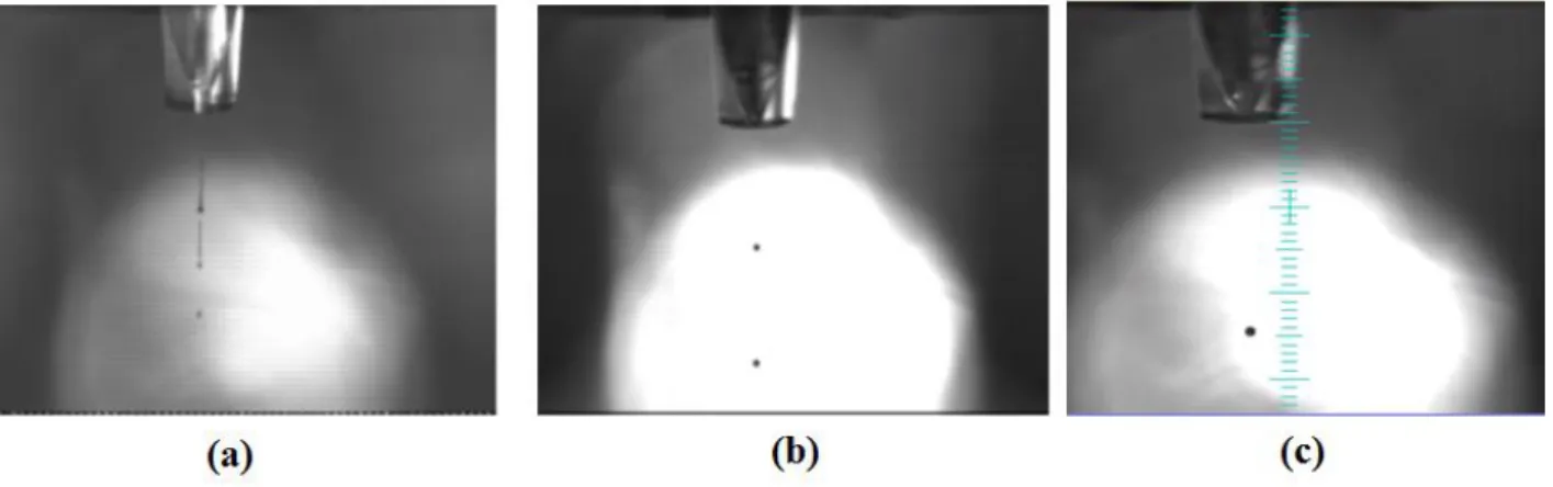
These pressure oscillations propagate through the printing fluid in the tube, resulting in the ejection of microdroplets. Stable droplet ejection is achieved by visually observing expelled microdroplets and adjusting voltage pulse parameters and capillary fluid backfill pressure to create an “ideal” drop. Drops are visualized using synchronized strobe illumination and a charged coupled device (CCD) camera. Fig. 2 shows the droplet formation sequence from the nozzle of the inkjet printer. Printing was performed at a jetting frequency of 400 Hz with a droplet velocity of ∼4.5 m/s. It was observed that, droplet velocities between 4 m/s and 6 m/s are ideal for printing homogeneous patterns. Droplet velocities less than 1 m/s may result in inaccurate drop placement. Thus, conditions that provide the highest drop velocity without satellite droplet formation are desired [22]. The motion control component and pattern monitor allowed for precise control of the length, width, and thickness of the coating by adjusting the pitch distances between droplets. In order to obtain smooth conductive
6
patterns with high resolution by ink-jet printing, various printing conditions, including the step (inter-spacing distance between dots) and drop diameter (sizes), the printing speed which is related with frequency, and the driving wave form was also optimized to obtain smooth and homogeneous coating layers.
Fig. 2. Drop generation from JetLab® 4 DOD inkjet printer. Drop ejection with (a) tail (elongation) &
multiple satellites before optimization that are not desired and can often be eliminated; (b) satellites after halfway of optimization; and stable droplet ejection (c) is achieved by adjusting voltage and pressure
parameters
The resulting printed silver lines (see Fig. 3) on the cleaned Kapton substrate was first heated to 130 °C on a hot plate, and held at this temperature for 10 min to convert the deposited silver nanoparticles into a conductive silver film.
7
This consists of two steps thermal curing procedure recommended by the ink supplier: a drying step to remove solvent and obtain a continuous structure.
Then a second sintering at 150 °C for 30 mn was done in a classical oven to obtain high conductive structure.
The Electrical functionality of the printed pattern was measured using a 4-point probes method after thermal curing. And a sheet-resistance and a resistivity of 0.163 Ω/sq and 5.9 µΩ.cm, respectively are obtained. These results are similar to those values reported in the datasheet of the ink supplier.
3. Resistive Temperature sensor on Kapton substrate 3.1. Design and characterization
Before the realization of the final prototype, a detailed study on the silver printed lines was performed. Many lines have been printed, which allowed us to determine and optimize the lines width and the spacing between each line. Moreover, during this preliminary study, it has been determined that the optimal droplet spacing for the best homogeneity is 90 µm and the droplet size measured on Kapton is ~190 µm. On twenty printed samples, the average width of lines calculated was 300 µm +/- 10 µm, and the average space was 60 µm +/- 2 µm.
This preliminary study resulted in the achievement of the final prototype sensor with the characteristics mentioned hereunder.
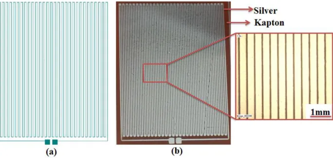
The temperature sensor covered an area of 2.85 cm x 2.26 cm. Two Ag layers were printed (2 inkjet passes). The printed lines have a width of 306 µm, an average thickness of 365 nm +/- 2.8 nm and a gap between the lines of 60 µm (see Fig. 4). A mechanical profilometer was used to measure the thickness of Ag printed lines.
8
Fig. 4. Photographs of (a) designed temperature sensor and (b) inkjet printed silver temperature sensor on Kapton substrate
3.2. Results and discussions
The relationship between the measured resistance and the temperature change can be expressed as [23]:
R(T) R0(1AT BT2 CT3). (1)
T represents the temperature in °C, R₀ is the value of the resistance at T = 0°C.
The relation (1) can be linearized for small temperature variation ΔT around T. This relation becomes:
R
(
T
T
)
R
(
T
)(
1
T
T
)
. (2) Where, T R T R T ) ( 1
. (3)αT is the sensitivity (temperature coefficient) of the sensor in units of °C-1 .
The temperature sensor was electrically characterized with means of a prober (SUSS) PM300 and an Agilent 4156C analyzer (used in range of voltage 0 to 1V). The temperature was regulated by an
9
advance temperature test bench (Advance Temperature Test Systems GmbH) between 20°C and 60°C.
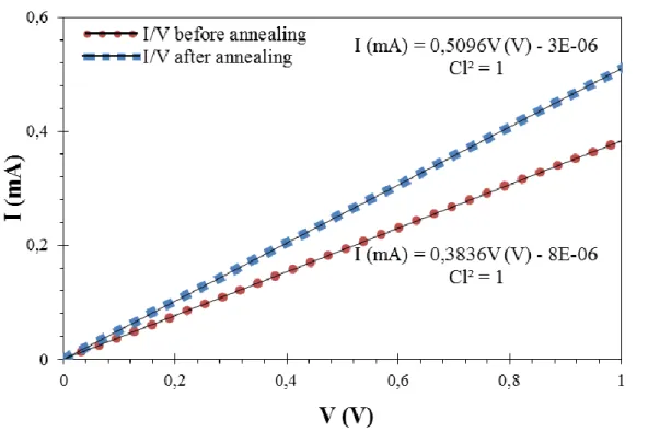
The sensor is characterized at ambient temperature before (just dried on a hotplate at 130 °C for 10 mn), and after further annealing at 150 °C for 30 mn (see Fig. 5).
Fig. 5. Measured current of the sensor temperature before and after annealing for a voltage between 0 V and 1 V at ambient temperature.
The resistance obtained at ambient temperature before annealing was 2.6 kΩ. With further annealing, the resistance of the sensor was reduced to 1.9 kΩ. The resistance change of the sensors after annealing were also determined as a function of temperature in a range of 20 °C to 60 °C both in ascending and descending order. This was done to determine the linearity, sensitivities and hysteresis of the printed sensor. The resistances obtained varied between 1.95 kΩ and 2.13 kΩ for ascending temperature with 0.9999 as coefficient of linearity (Cl2) after linear fitting. And, for descending temperature the resistances varied between 1.94 kΩ and 2.13 kΩ, and the coefficient of linearity after linear fitting was 0.9998. The sensitivity of the sensor was 2.19*10ˉ³ °Cˉ¹ with a
10
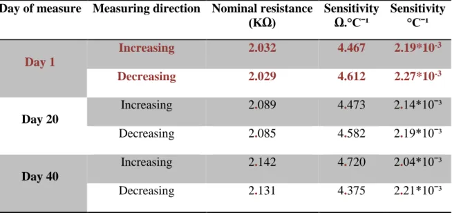
nominal resistance of 2.032 kΩ at 38.5°C in increasing temperature order. In decreasing temperature order, the sensitivity was 2.27*10ˉ³ °Cˉ¹ with a nominal resistance of 2.029 kΩ at 38.5 °C. As the sensor was intended for medical applications, the range of interest is between 35 °C and 42 °C, that’s why the nominal resistance is measured at 38.5°C.
The sensitivity was lower than the usually reported for bulk Ag. This reduction was commonly observed in printed [24] metallic thin film.
The temperature sensor that we realized has the same order of magnitude of that shown by other inkjet printed silver temperature sensor [10, 25] (Table 1).
Day of measure Measuring direction Nominal resistance (KΩ) Sensitivity Ω.°Cˉ¹ Sensitivity °Cˉ¹ Day 1 Increasing 2.032 4.467 2.19*10-3 Decreasing 2.029 4.612 2.27*10-3 Day 20 Increasing 2.089 4.473 2.14*10ˉ³ Decreasing 2.085 4.582 2.19*10ˉ³ Day 40 Increasing 2.142 4.720 2.04*10ˉ³ Decreasing 2.131 4.375 2.21*10ˉ³
Tab. 1. Sensitivities and nominal resistances at 38.5°C of silver temperature sensor over time.
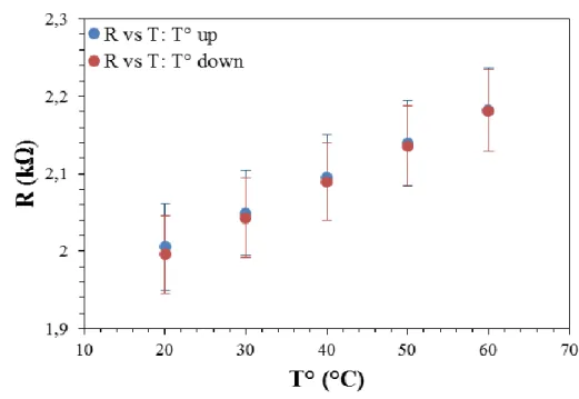
To observe the variation of results over time (see fig. 6), measurements were made with a 20 day interval. An increment in nominal resistance of +/- 50 Ω and a maximum variation in sensitivity of 0.1*10-3 °C-1 have been observed. Since the sensor was not protected, this variation is may be due to oxidation of Ag in time.
11
Fig. 6. Resistance versus temperature over time of the printed temperature sensor
The results of the measurements are summarizing in table 2 and in the two measuring senses (ascending and descending temperature order).
The maximum variations between the results in increasing and decreasing temperature were evaluated in the extended range of sweep value. It was obtained less than 3 % in the two first measurements and 10% in the last one (see Tab. 2). The results suggest the need for coating layers to protect the printed silver patterns.
Day of measure Hysteresis (%)
Extended of the measurement (Ω)
Day 1 3.01 184
Day 20 2.82 183
Day 40 9.69 192
12 Conclusions
An organic silver complex compound ink was inkjet printed on a Kapton substrate. Optimal jetting parameters were found to obtain smooth and homogeneous silver coating layers and a large meander forming the sensor. The thickness and the resistivity found for two Ag printed layers were 365 nm and 5.9 µΩ.cm, respectively. The sensitivity of the printed temperature sensor obtained in the range of 20 °C to 60 °C was 2.19*10ˉ³ °Cˉ¹ with a nominal resistance of 2.032 kΩ at 38.5°C. We observed a good linearity and a hysteresis less than 5% in the extended measurement. The variation over time of the sensitivity and nominal resistance was also observed. To improve the stability and the performance, the sensor will be protected to the next step of the work.
Acknowledgments
Authors would like to acknowledge all the partners of the VEADISTA project and the FUI DGCIS for financial support.
References
[1] N. Jeranče, D. Vasiljević, N. Samardžić and G. Stojanović, “A Compact Inductive Position Sensor Made by Inkjet Printing Technology on a Flexible Substrate”, Sensors 2012, 12, pp. 1288-1298; doi:10.3390/s120201288.
[2] Chin-Tsan Wang, Kuo-Yi Huang, David T. W. Lin, Wei-Chia Liao, Hua-Wei Lin and Yuh-Chung Hu, “A Flexible Proximity Sensor Fully Fabricated by Inkjet Printing”, Sensors 2010, 10, pp. 5054-5062; doi:10.3390/s100505054.
[3] Z. Abadi, V. Mottaghitalab, M. Bidoki, A. Benvidi, “Flexible biosensor using inkjet printing of silver nanoparticles”, Journal Article Aug 2014, Sensor Review volume 34 issue 4, pp. 360-366, http://dx.doi.org/10.1108/sr-07-2013-704.
13
[4] E. Starke, A. Turke, M. Krause, W.-J. Fischer, ”Flexible polymer humidity sensor fabricated by inkjet printing”, Conference Paper Jun 2011, 16th International Solid-State Sensors, Actuators and Microsystems Conference, http://dx.doi.org/10.1109/transducers.2011.5969254 .
[5] M. Acuautla, S. Bernardini, L. Gallais, T. Fiorido, L. Patout, M. Bendahan, “Ozone flexible sensors fabricated by photolithography and laser ablation processes based on ZnO nanoparticles”, Sensors and Actuators B 203 (2014) pp. 602–611; http://dx.doi.org/10.1016/j.snb.2014.07.010.
[6] S. Khan, L. Lorenzelli, R.S. Dahiya, “Technologies for printing sensors and electronics over large flexible substrates: a review”, IEEE Sensors Journal, Vol. 15, NO. 6, June 2015, pp. 3164-3185.
[7] K. Schroeter, "Printed sensors: enabling new applications", Sensor Review, Vol. 28 Iss: 1, 2008, pp.6 – 11.
[8] G. Chansin, “Printed and flexible sensors 2014-2024: Technologies, Players, Forecasts”, IDTechEx Report, Aug. 2014.
[9] D. Briand, A. Oprea, J. Courbat, and N. Bârsan, “Making environmental with the emergence of the printed electronics industry, the development,” Materials Today, vol. 14, no. 9, pp. 416–423, 2011.
[10] J. Courbat, Y. B. Kim, D. Briand, and N. F. De Rooij, “INKJET PRINTING ON PAPER FOR THE REALIZATION OF HUMIDITY AND TEMPERATURE SENSORS “, Ecole Polytechnique Fédérale de Lausanne ( EPFL ), Institute of Microengineering ( IMT ), Sensors , Actuators and Microsystems Laboratory ( SAMLAB ), Neuchâtel , Switzerland,” pp. 1356– 1359, 2011.
[11] D. Briand, F. Molina-Lopez, A. V. Quintero, C. Ataman, J. Courbat, and N. F. de Rooij, “Why Going Towards Plastic and Flexible Sensors?,” Procedia Engineering, vol. 25, pp. 8–15, 2011.
14
[12] F. Varela, E. Armendáriz, and C. Wolluschek, “Inkjet printed electronics: The wet on wet approach,” Chemical Engineering and Processing: Process Intensification, vol. 50, no. 5–6, pp. 589–591, May 2011.
[13] E. Halonen, V. Pynttäri, J. Lilja, H. Sillanpää, M. Mäntysalo, J. Heikkinen, R. Mäkinen, T. Kaija, and P. Salonen, “Environmental protection of inkjet-printed Ag conductors,” Microelectronic Engineering, vol. 88, no. 9, pp. 2970–2976, Sep. 2011.
[14] B. J. Kang, C. K. Lee, and J. H. Oh, “All-inkjet-printed electrical components and circuit fabrication on a plastic substrate,” Microelectronic Engineering, vol. 97, no. 4023, pp. 251–254, Sep. 2012.
[15] B. Baker, “Temperature sensing technologies,” AN679, Microchip Technology Inc, 1998. [16] C. Lee, S. Lee, and Y. Lee, “In situ monitoring of temperature using flexible micro
temperature sensors inside polymer lithium-ion battery,” Nano/Micro, pp. 698–701, 2012. [17] C.-Y..Lee, G.-W. Wu, W.-J. Hsieh,” Fabrication of micro sensor on a flexible substrate”,
sensors and Actuators A 147 (2008) pp.173-176.
[18] S. Bielska, M. Sibinski, A.Lukasik, “Polymer temperature sensor for textronic applications”, Materials Science and Engineering B 165 (2009) pp.50–52.
[19] D. Briand, F. Molina-Lopez, A. Vásquez Quintero, G. Mattana, N.F. de Rooij, “Printed Sensors on Smart RFID Labels for Logistics”, 978-1-4673-0859-5/12/$31.00 ©2012 IEEE. [20] B. Meier, L. Egermann, S. Voigt, M. Stanel, H. Kempa, A.C. Huebler, “Drift in the resistance
of poly(3,4-ethylenedioxythiophene):poly(styrenesulfonate) printed films during thermal cycling”, Thin Solid Films 519 (2011) pp.6610–6612.
[21] http://www2.dupont.com/Kapton/en_US/assets/downloads/pdf/Gen_Specs.pdf.
[22] MicroFab Technologies, Inc. MJ-AT User's Manual. Available online: http://www.microfab.com/images/pdfs/manuals/mj-at_manual.pdf (accessed on 7 January 2015).
15
[23] Georges Asch et coll., "les capteurs en instrumentation industrielle", pp.252-265 ,7ème édition, Dunod, Série EEA.
[24] J. Felba et al., "The influence of thermal process on electrical conductivity of microstructures: made by ink-jet painting with the use of ink containing nano sized silver particles," in IEEE-NANO 2009, 9th IEEE Conference on Nanotechnology, Genoa, 2009, pp. 408-411.
[25] G. Mattana, T. Kinkeldei, D. Leuenberger, C. Ataman, J. Jinyu, F. Molina-lopez, A. V. Quintero, G. Nisato, G. Tröster, D. Briand, and N. F. De Rooij, “Woven Temperature and Humidity Sensors on Flexible Plastic Substrates for E-textile Applications”, Sensors Journal, IEEE, volume 13, pp 3901-3909, 2013.