HAL Id: cea-02509778
https://hal-cea.archives-ouvertes.fr/cea-02509778
Submitted on 17 Mar 2020
HAL is a multi-disciplinary open access
archive for the deposit and dissemination of
sci-entific research documents, whether they are
pub-lished or not. The documents may come from
teaching and research institutions in France or
abroad, or from public or private research centers.
L’archive ouverte pluridisciplinaire HAL, est
destinée au dépôt et à la diffusion de documents
scientifiques de niveau recherche, publiés ou non,
émanant des établissements d’enseignement et de
recherche français ou étrangers, des laboratoires
publics ou privés.
System option
G. Laffont, D. Plancq, L. Cachon, O. Gastaldi, J. Quenaut, D. Robertson
To cite this version:
G. Laffont, D. Plancq, L. Cachon, O. Gastaldi, J. Quenaut, et al.. Status of studies on ASTRID Gas
Power Conversion System option. ICAPP 2016 - 2016 International Congress on Advances in Nuclear
Power Plants, Apr 2016, San Francisco, United States. �cea-02509778�
Contact: david.plancq@cea.fr
Status of studies on ASTRID Gas Power Conversion System option
Guy LAFFONT
1, David PLANCQ
1, Lionel CACHON
2, Olivier GASTALDI
2, Johann
QUENAUT
3, Dan ROBERTSON
41 CEA Cadarache, DEN/DER/CPA, 13108 Saint-Paul lez Durance Cedex, France
2 CEA Cadarache, DEN/DTN, 13108 Saint-Paul lez Durance Cedex, France
3 GE Power, 3 Avenue André Malraux 92300 Levallois Perret, France
4 Rolls-Royce, Alantic House (AH-G-CN), PO Box 2000, Derby, DE21 7XX, England
Abstract
Within the framework of the French 600 MWe Advanced Sodium Technological Reactor for Industrial Demonstration ASTRID project, two options of Power Conversion System (PCS) were investigated during the conceptual design phase (2010-2015):
• the use of a classical Rankine water-steam
cycle, similar to the solution implemented in France in Phenix and Superphenix, but with the goal of greatly reducing the probability of occurrence and limiting the potential consequences of a sodium-water reaction; chosen as the reference during the ASTRID conceptual design phase due its high level of maturity
• a gas solution based on the Brayton cycle,
which has never been implemented in any sodium reactor but has been investigated for High Temperature Reactors (HTR). Its application is mainly justified by safety and acceptance considerations in inherently eliminating the water and sodium-water-air reactions risk existing with a Rankine cycle.
This paper synthetizes the important efforts focused during the ASTRID conceptual design phase on the Gas Power Conversion System option, in order to increase its maturity level. It describes the main characteristics defined, throughout Option Selection Processes, as the reference for the further ASTRID Basic Design phase. In Particular, the turbomachinery, the Sodium Gas Heat Exchangers (SGHE) and general layout as well as expected performances, operability and safety analysis are detailed.
I. INTRODUCTION
The Sodium-cooled Fast Reactor (SFR) is one of the Generation IV reactor concepts selected to secure the nuclear fuel resources and to manage radioactive waste. Within the framework of the June 2006 act on
the sustainable management of radioactive material and waste, the French Government asked CEA to conduct design studies for the Advanced Sodium Technological Reactor for Industrial Demonstration (ASTRID) project [1] in collaboration with industrial partners [2].
ASTRID will be an integrated technology prototype designed for industrial-scale demonstration of 4th-generation Sodium-cooled Fast Reactor (SFR)
safety and operation aiming at improving safety, operability and robustness levels against external hazards compared with previous SFRs.
The pre-conceptual design phase – AVP1 conducted from mid-2010 to the end of 2012 – has been focusing on innovation and technological breakthroughs, while maintaining risk at an acceptable level. This phase has been followed by the AVP2 conceptual design phase planned until the end of 2015 whose objectives were to focus on the design in order to finalize a coherent reactor outline and to finalize by December 2015 the Safety Option Report.
The ASTRID conceptual design is based on a sodium-cooled pool reactor of 1500 MWth with an intermediate circuit in sodium generating about 600 MWe. The target lifetime for ASTRID is 60 years. Among the numerous open options investigated during the AVP1 pre-conceptual design phase, two Power Conversion Systems (PCS) were studied in parallel during the AVP2 conceptual design phase based on a Rankine steam cycle and a Brayton gas cycle.
The steam PCS option is the most mature option. As it is the power conversion system for all SFRs up to now, it benefits from a large experience and tens of unit-operating years. For this option, conventional 180bar/500°C steam cycle conditions have been selected. Nevertheless, the always present sodium-water and sodium-sodium-water-air reactions risk is a strong design and operation constraint to be overcome.
The closed Brayton gas PCS option is generally considered as the likely choice for High Temperature Reactors (HTR), as it provides at 800°C temperature range better cycle net efficiency than the best
Rankine cycle. Application of Nitrogen closed Brayton cycle for a sodium cooled fast reactor in the 500°C temperature range is mainly justified for safety and acceptance considerations by inherently eliminating the sodium-water reaction risk existing in a Rankine cycle.
During the ASTRID AVP2 phase from 2013 to 2015, a strong R&D effort has been focused on the gas PCS in order to increase its maturity level, with a limited number of actions on the steam PCS (focused on steam generator materials and sodium water reaction studies).
Based on the ASTRID conceptual design phase studies, this paper discusses the general assessment on the Gas Power Conversion System option, especially Nitrogen system, in order to increase its maturity level and details the main characteristics embedded in the ASTRID Basic design Phase.
II. ASTRID GAS CYCLE PERFORMANCE
The reference cycle for the ASTRID Power Conversion System is a closed Brayton cycle in pure nitrogen at 180 bar (figure 1). The turbine and the compressors are placed on the same shaft line as the turbogenerator. Aiming at optimizing the cycle, the gas is cooled before the high pressure compressor inlet to limit the compression work and an economizer allows raising the temperature of the gas returning to the Sodium Gas Heat Exchangers (SGHE) with heat extracted from turbine outlet gas.
The reference solution for the heat sink is a wet cooling tower. The closed cooling water system provides the cooling medium for the pre-coolers and coolers.
The main boundary conditions for the thermodynamic gas cycle calculations are the following:
• Thermal power delivered to the gas cycle: 1502 MWth
• Sodium gas heat exchanger outlet temperature: 515°C
• Sodium gas heat exchanger outlet pressure: 180 bar
• Sodium gas heat exchanger inlet temperature: 310°C
• Cooler outlet temperature: 27°C
The net efficiency is around 37 %, taking into account cooling requirements, sodium pumps and auxiliary power.
FIG.1. Reference Brayton cycle
III. THE GENERAL LAYOUT OF GAS PCS
At the beginning of the AVP2 phase, a techno-economic analysis has been conducted on the ASTRID gas PCS to compare variations of the requirements to the AVP1 Reference [4] to see if a “better” overall solution could be achieved. Four areas have been looked at:
• Pipe gas velocity, • Maximum pressure, • Number of shaft lines, • SGHE temperature.
Modifying each of these parameters can potentially lead to important savings with respect to total mass of pipes and inventory. On top of that, a change of the SGHE gas inlet temperature can also significantly reduce the size of the SGHE and of the economizers. This investigation has confirmed that the maximum cycle pressure shall remain at 180bar since its effect on cycle efficiency is too important.
However, this study also suggested that the number of shaft lines should be doubled and the gas velocity shall be increased to permit a reduction of the number of pipes in the turbine hall by a third. With respect to the SGHE temperature, a decrease of the gas outlet temperature is not advised since its impact on the efficiency is too strong. It has been recognized that a decrease of 30°C of the inlet temperature would give the profit optimum. However, due to the uncertainties on the cost evaluation and on the relative profit optimum, it has been decided to limit the temperature decrease to 20°C, thus enabling the suppression of one SGHE module per loop. A decrease of 20°C will keep the net efficiency of the cycle close to 37%, while permitting a significant saving on the size of the heat exchangers. Compared to the reference AVP1 plant, the following savings have been observed at the end of AVP2:
• Mass of pipes: -58%, • Inventory: -50%, • SGHE size: -36%,
ICAPP 2016 San Francisco, US, April 17-20, 2016 Paper 16442 • Exchange surfaces size: -35%,
• Mass flow: -10%.
The net efficiency of this solution is expected to be around 37%, which represents a decrease of 0.5% point compared to the reference AVP1 plant.
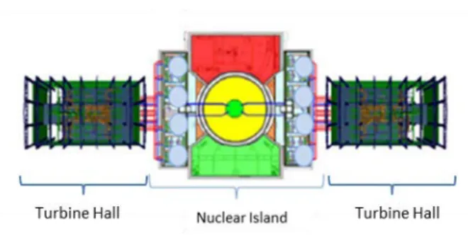
In this configuration with two turbogenerators, each turbogenerator unit is laid out in independent turbine halls and connected to four SGHE, two SGHE per intermediate sodium loop (figure 2).
FIG. 2: Reactor layout
This configuration led to a strong reduction of the number of gas lines and equipment, of the steel and nitrogen inventories (divided by a factor 2) and of the gas supply system. In addition, the simplification of the gas piping layout allowed a better arrangement of the turbine hall with easier accessibility and maintainability.
IV. THE HEAT EXCHANGERS
IV.A. The Sodium Gas Heat Exchanger (SGHE)
Due to their very innovative design and operating conditions, The Sodium Gas Heat Exchangers (SGHE) is leading to a main technological challenge. The Sodium Gas heat exchanger is based on a compact plate heat exchanger technology. Two options have been investigated: one by the CEA, the other one by Rolls-Royce.
The CEA SGHE concept is a component of a unit power of 187,5 MWth (2 components per secondary loop), using a technology of plate assembly by high isostatic pressure diffusion bounding manufacturing process (HIP-DB) [5].
The principle of this design of SGHE is based on a component integrating 8 elementary modules of compact heat exchanger into a pressurized vessel which also plays the role of inlet manifold (Figure 3). These design options aim at:
• limiting the impact of a failure of the exchanger module towards the outside, the external vessel
constituting the second sodium containment barrier,
• limiting the impact of a failure of the module on the secondary circuit: the maximal nitrogen leak section in the sodium is reduced, and the sodium manifolds are brought out the pressure vessel, • limiting the thermo-mechanical stresses: the
pressure vessel structures are maintained at the heat exchanger low temperature, i.e. 310°C, and the plates are maintained in compression,
• minimizing the sodium inventory in the components,
• maximizing compactness and minimizing the pressure drop.
The thermomechanical analysis shows that:
• a classical pressure vessel design is required with limiting size and thickness due to manufacturing reasons,
• sodium pipes inside the vessel are both thermal and external pressure loaded leading to a risk of buckling. This type of loading is not investigated in the RCCMRx Design and construction rules [6] leading to use complex general assessment rules, whose first results seem to give acceptable solutions.
The significant weight of the pressure vessel and the fact that the internal sodium pipes are loaded by an external pressure are the main drawbacks of this concept. An alternative solution with external gas and sodium manifolds is being investigated.
Few mock-ups at small scale (40kW) have been manufactured and tested on the DIADEMO facility (CEA) in representative conditions.
FIG. 3: CEA SGHE Concept
The Rolls-Royce design is based on their industrial feedback on the heat exchanger field. Rolls-Royce proposes a 187.5 MWth component based on compact modules connected in parallel and provided with external manifolds. This technological option eliminates the external pressure vessel. Rolls-Royce has previously supplied compact heat exchangers of
this configuration to the oil and gas processing industries.
FIG.4: Rolls-Royce SGHE Concept In the first phase of the study, the manufacturing process of channels and plate assembling was based on superplastic forming and high isostatic pressure diffusion bonding (SPF-DB). The advantage of this method is to achieve the exchanger plates in once-through. This process is mastered by Rolls-Royce for materials such as titanium. The challenge is to demonstrate its applicability to stainless steel 316 L (N), the material chosen for the sodium-gas heat exchangers. Testing by Rolls-Royce end of 2014 showed that the SPF-DB needed process parameters (very low strain rates at high pressure) past the superplastic standard forming capabilities. Indeed, the intrinsic properties of stainless steel 316L (N) are not suitable to superplastic deformation, and if the door is not completely closed for this type of process, the current knowledge does not allow an on time qualification.
It was therefore decided to investigate an alternative manufacturing technology. High pressure isostatic is used to diffusion bond laminated sheets together to form the exchanger plates. The modules are then produced by the stack of plates bonded by diffusion. The industrial feasibility of this manufacturing process is being analyzed.
IV.B. The other exchangers
The Brayton thermodynamic cycle is given in figure 1. The optimization of the cycle leads to the choice of:
• An economizer between the high pressure and low pressure lines of the cycle increasing the average operating temperature of the SGHE. • A two-stage compression with appropriated
cooling to limit the compression work and the power input to the shaft-line.
The operating conditions of these components in terms of pressure and temperature are less severe than these imposed on sodium / gas exchangers.
The economizer (also called recuperator) is a gas / gas exchanger between the high pressure and low pressure lines that passively cools the expanded gas from the turbine outlet and heat the recompressed gas before the SGHE to raise the average temperature of the heat source and thus improve the cycle efficiency. The pre-design studies carried out on this high power component show that only a modular PCHE/PFHE technology of compact exchangers is feasible for reasons of compactness and allowable mechanical load.
The pre-coolers and coolers are gas / water exchangers for cooling the compressor inlet gas to limit the compression work. They operate at the bottom pressure levels and temperature of the cycle (at pressures below 110 bar, temperatures below 100°C). The use of compact heat exchangers for these coolers leads to a gain in thermal compactness at least a factor of 10 compared to the shell and tube concepts. Furthermore, without grid, penalizing in terms of size and cost, it is not possible to implement PSHE type exchangers. Therefore, the modular technology of PCHE/PFHE compact heat exchangers technology was also withheld for gas cycle coolers.
V. THE TURBOMACHINERY
The turbomachinery of both shaft lines is based on 2 split flow axial turbines, one Low Pressure and one High Pressure radial Compressors on the same shaft line as the turbogenerator. The design of the turbomachinery has been pre-defined together with the main ancillary systems. All key technologies have references in the industry and the feasibility of the turbomachinery is confirmed.
V.A. The turbine
The driving machinery is a pair of multi-stage axial nitrogen turbine arranged in opposite direction (split-flow concept) to balance the axial thrust. A bifurcated inlet guides the flow from the two incoming pipes to the blade area. A bifurcated outlet guides the flow leaving the last stage blade to the 2 outlet pipes (Figure 5). A barrel outer casing ensures tightness while minimizing thermal distortions. The seals are mechanical dry gas seals that minimize the shaft leakage. The bearings are conventional 5 pad tilt-pad bearings. These 2 elements are enclosed in the bearing housing.
A comparison between axial and radial technologies has been performed concluding that the
ICAPP 2016 San Francisco, US, April 17-20, 2016 Paper 16442 axial technology was the most suitable for the turbine.
Trade studies were performed between a single flow turbine plus balance piston vs. a split-flow turbine. Whilst the single flow turbine aerodynamic efficiency was higher due to a lower blade clearance to blade length ratio, this increase was more than offset by balance piston leakage. In addition, it is very difficult to determine the actual value of the thrust. A split flow back-to-back turbine configuration reduces then the risk related to this thrust value uncertainty. This has also the benefit to lower blade gas bending loads due to shorter blade and twice the number of rows. Blade aeraulic and thermomechanic assessments have been performed. The configuration with 2 shaft-lines halves the mass flow and reduces the blade height by about one third. It leads to a decrease of 50% of mechanical stresses. The feasibility of turbine blade and wheelsis confirmed in this configuration.
The radial gap between the rotor blade and the stator also has a significant impact on the isentropic efficiency of the turbine and the overall cycle efficiency. It has been estimated that a gap change of 1mm represents a variation of 0.5 point on the plant efficiency. Therefore, this gap should be minimized while allowing for differential expansion between the stator and the rotor to increase the effective turbine torque.
The blade roughness also has an influence on the turbine efficiency and mustn’t be neglected as these losses can represent up to 50% of the total losses of the turbine. For ASTRID, a conventional machining process has been considered. Polishing surfaces and reducing the roughness should lead to an efficiency improvement of the turbine up to 1 point.
In the two shaft lines configuration, pipe lines connecting the turbine to the upstream and downstream components are limited to 4, with two inlet/outlet piping per turbine casing. The reduction of the number of inlet / outlet piping simplifies penetrations and allows returning to more conventional solutions compared to the one shaft line configuration.
A solution featuring a turbine inlet and outlet volutes concept has been studied. Bifurcated option was chosen for the turbine inlet and outlet due to lower mechanical loading and pressure drop, as well as simplified manufacturing.
Turbine casings are subjected to high internal pressure, especially at the turbine inlet. To limit casing ovalization causing leakage between turbine stages and a drop in performance, the current concept provides a double envelope with internal pressure balance.
Concerning the rotor, the technology used is a welded rotor technology, considered as a standard in
the constructor experience. The main motivation of the welded rotor choice is the minimization of the mass/moment of inertia ratio allowing a better behavior when going through the turbine critical speed during speeding up/slowing down, and thus allowing the minimum radial clearances to be set. Thermal, thermomechanical and rotor dynamic analysis confirm the feasibility of the welded rotor.
FIG. 5: Nitrogen turbine
V.B. The compressors
Both axial and radial technologies were further analyzed. The radial technology has been maintained for its simplicity and robustness, but with a 2-stage transition to maintain a good efficiency (figure 6).
In the same way as the opposite turbine arrangement, the shaft line features a face-to-face mounting of the HP compressor and LP compressor. The axial thrust loads are then opposed and the residual thrust being taken over by a relatively small sized balance piston.
Compared to the single shaft line arrangement, the reductions of the wheel diameters and of the mass flow have decreased mechanical stresses on the blades and the casings the number of casing penetrations and allow for an easier manufacturing of wheels.
A good mechanical behavior of the wheels is expected even for maximum over-speed.
Considering two shaft lines, pipe lines connecting the compressors to the upstream and downstream components are reduced to 2, with two inlet/outlet piping per compressor. The reduction of the number of inlet/outlet piping allows choosing a plenum manifold for the inlet of the compressor and a volute for the outlet.
Thermomechanical analysis of the staged pressure vessel shows that stress limits are widely observed. Only a few specific points are beyond the limits while remaining well below the allowable stress limit. To confirm the mechanical integrity of the pressure
vessel, an elasto-plastic analysis was performed in accordance with the European Unfired Pressure Vessel Standard. This analysis has shown that all criteria were passed with a minimum lifetime greater than 10000 cycles for the most-strained areas of the casings.
FIG. 6: 2-stage compressor
V.C. The Turbomachinery feasibility
The design of the turbomachinery has been further simplified and consolidated. Performance and mechanical behavior of the components have been confirmed. The maturity of the technology solution has been improved and all the identified key technologies for the turbomachinery are referenced in the Power industry (Figure 7). Several optimizations have been identified to reduce the masses of the components in particular pressure vessels for which large areas are very lightly loaded and to improve performance of the turbomachine. These studies may be initiated from the beginning of the basic design phase.
FIG 7: Turbomachinery key technology
VI. THE TURBINE HALL LAYOUT
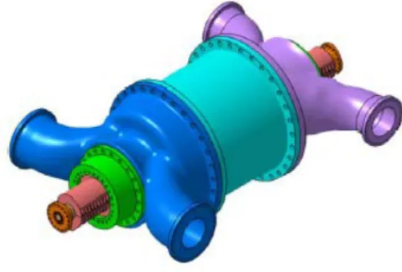
On the shaft-line, the double flow turbine is located between the compressor and the turbogenerator, so in the postulated case of break of
the shaft, the turbine is driving either the compressors or the turbogenerator, thus limiting the over-speed risk of the turbine (Figure 8).
FIG. 8: Turbomachinery Shaft-line
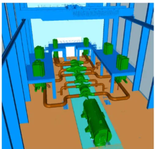
The first drawing of a single Power Conversion System leads to a shaft line length of about 40 meters, a turbine hall of about 35m wide and 63 m length, for a height of about 25 m (Figure 9). The whole volume of the two turbine halls is half less than the previous configuration with only one shaft-line.
FIG. 9: Turbine Hall Layout
VII. NITROGEN INVENTORY SYSTEM
Actual load of the shaft line is driven by the specific volume of the gas in the turbine. The nitrogen inventory system allows the voiding and filling of the tertiary nitrogen circuit and allows management of the mass of gas in the tertiary circuit and thus the mean operating pressure according to the various operating conditions of the reactor. Note that rapid transients will primarily be managed by equipment bypasses (see chapter 8 below). .
A preliminary study and a technico-economic evaluation were performed in AVP1 phase to define a first sizing of the inventory management system of tertiary nitrogen circuit. These studies led to the selection of a management system combining storage pressure spheres and filling/voiding compressors. A nitrogen supply system is necessary for leakage compensation. Based on architecture with two shaft lines, the AVP2 design led to a significant reduction
ICAPP 2016 San Francisco, US, April 17-20, 2016 Paper 16442 in required nitrogen inventory. Moreover, each
turbomachinery is connected to its own inventory management system. The pressure vessels can thus be spherical or cylindrical vessels and be partially or completely buried. Periodic inspections may be made by acoustic emission methods, industrial technology also used for buried volumes. The principle of an on-site nitrogen production is also selected to facilitate the supply of leakage loss in normal operation of the reactor.
VIII. OPERABILITY
The Gas PCS operability has been studied and procedures have been defined with respect to the various considered transient situations. As far as the Gas PCS is concerned, reactor needs result in the sodium temperature variations at the inlet and at the outlet of the SGHE and the thermal power to be extracted.
The power extracted from the SGHE by the gas PCS is controlled by:
• The mass flow rate of gas through the sodium-gas heat exchangers,
• The gas inlet temperature in SGHE.
Four parameters control the mass flow through the gas-sodium exchangers:
• The speed of the turbomachinery: The speed variations are possible only when the turbogenerator is disconnected from the electrical grid.
• The nitrogen inventory in the cycle: these nitrogen pressure variations in the gas path are relatively slow and can’t provide quick fixes on extracted power.
• The bypass of the compressor: the compressors are equipped with bypass to prevent compressor surge. The bypass can be used to divert a portion of the gas flow in exchangers while maintaining constant mass flow in the compressor.
• The bypass of SGHE or Economizer: it is possible to divert a portion of the gas flow to reduce the thermal load of the respective heat exchanger.
A first analysis has allowed the definition of procedures for the various considered transient situations using a combination of turbine speed variations, nitrogen inventory and a by-pass of the economizer (dedicated to control the inlet temperature in the SGHE).
Regarding the normal startup, the turbogenerator will be used as a starter motor. Once at 3000 rpm, the shaft line can be synchronized to and then connected to the grid. Then, the power increase is
managed by the nitrogen inventory. With respect to the normal shutdown, the reverse procedure is applied. The power decrease is managed by the nitrogen inventory until the turbogenerator is disconnected from the grid, then the turbomachinery trip bypass is used to ensure power is taken from the grid.
In case of automatic shutdown (SCRAM), the sodium loops cool down, the heat removed from the SGHE decreases. This procedure is a fairly quick event. Therefore, it is assumed that a reduction of the inventory will not be used and the full inventory will stay in the main gas loop. The considered solution is to reduce the shaft speed; the turbomachinery trip bypass is therefore opened in order to go into motor mode. The turbogenenerator is then decoupled from the grid.
A preliminary analysis of specific normal or accidental transients was carried out to assess the impact on primary and secondary reactor circuits, when the initiating event is located at the tertiary circuit (Gas PCS) and a comparison has been performed with an equivalent transient from steam PCS.
The transients selected for this study were: • Loss of load (turbine trip),
• Loss of heat sink, • Break in main gas piping.
For each transient, the effects on the primary and secondary circuits are quite equivalent. The comparison between the two PCS options concludes that the effects of a loss of tertiary cooling are equivalent, and even weaker in case of Gas PCS, leading in no unacceptable consequence for the primary and secondary circuit.
IX. PRELIMINARY SAFETY ANALYSIS
The absence of sodium-water at the interface between the secondary fluid and tertiary is an undeniable advantage of the Gas PCS for the safety demonstration. Gas PCS also allows to make possible the exclusion of large sodium-water reaction if it is removed in the way in the other places of the reactor, including washing facilities.
The impact of Gas PCS on key safety functions (reactivity control, cooling and containment) was analyzed qualitatively and compared to steam PCS. Concerning the reactivity control, the Gas PCS takes the advantage in the fact that core gas ingestion and core compaction are easier to manage with a suitable design of the Intermediate Heat Exchangers, as a SGHE leakage behavior is physically much less severe that a sodium water reaction in a steam
generator. Concerning the containment, the Gas PCS inherently eliminates the sodium-water-air reactions risk in the exchanger buildings. In addition, there is no risk of leakage self-evolution (no wastage), no production of hydrogen or soda.
This leads to a simplification of the secondary sodium systems.
X. ANOXIA RISK
A pressurized nitrogen installation in operation can cause, in case of normal or incidental leakage, unnoticeable depletion of oxygen atmosphere and a risk of anoxia for staff. For ASTRID Gas PCS, anoxia risk is first linked to the permanent nitrogen leaks through the shaft-line seals during normal operation. The nitrogen density being very slightly less than that of air, it is necessary to ensure a fresh air supply and exhaust in the turbine hall in order to ensure a renewal of the atmosphere.
In normal condition, the nitrogen leak rate on each Shaft-line with mechanical seals technology is small compared to the turbine hall volume. The design of the ventilation of the turbine hall (steam or gas) has been performed with a standard value of turnover for industrial premises i.e. 1 vol./h. the permanent supply due to nitrogen leaks on the shaft line of the turbomachinery leads to a gap nitrogen equilibrium concentration of 10-4 with respect to the normal
concentration in the air.
The margin with respect to the anoxia risk is thus important.
The other initiator of the risk of anoxia is the accidental loss of nitrogen sealing devices. If a leakage appears on an instrumentation ¼ inch tube, the nitrogen supply with respect to the normal concentration is less than 0.2%. The evacuation of staff, informed by the functional consequences of the loss of sealing, or by triggering alarms, can be easily ensured.
In case of a large break in main gas piping in the turbine hall leading to the release of all of the nitrogen inventory (100% nitrogen atmosphere in the engine room), with a standard turnover rate of 1, normal air atmosphere is renewed after 3h.
This analysis shows that the anoxia risk is manageable with a standard ventilation design in the turbine hall and with preventive measures (detectors…) plus procedures limiting the access and managing evacuation (alarms, flashing lights …). If necessary, additional devices may be provided.
XI. TRITIUM MANAGEMENT
In Sodium fast Reactors (SFRs), the tritium produced in the reactor core migrates by transfer to the inerting gas in the primary circuit and by diffusion through the fuel cladding and components (intermediate exchangers, reactor vessel, pipes of various circuits …). It accumulates in large part in the purification units (cold traps) of primary and secondary sodium circuits. Very low amounts are however found in the circuits and components of the reactor and are liable to migrate through their walls to the outside atmosphere.
In the case of a steam PCS, the hydrogen produced in the tertiary circuit by corrosion of the steam generators tubes and by thermal decomposition of hydrazine migrates in the opposite direction to the tritium towards the secondary circuit and promotes the trapping of tritium by co-crystallization. In the case of gas PCS, hydrogen transfer from the tertiary to the secondary does not occur naturally. The trapping of tritium in the cold traps of the secondary circuit would be significantly less effective and the transfer of tritium would be more important at the tertiary circuit resulting in annual release tritium gas 15 times higher than steam PCS release. It is therefore necessary to increase tritium trapping performance at the secondary circuit in the case of gas PCS to limit tritium transfer to the tertiary circuit. It appears that the introduction of a very small amount of hydrogen in the secondary sodium circuit has a very important effect to the efficiency of trapping of tritium in the cold traps of the secondary circuit. The hydrogen injection in the secondary circuit is therefore the reference solution. With a hydrogen injection equivalent to the permeation flow through the steam generator, levels of annual tritium releases remains equivalent to Steam PCS release.
This analysis shows that, in normal conditions, ASTRID will have both limited and mastered tritium impact , environmentally speaking and regardless the PCS (gas or steam).
XII. QUALIFICATION PROJECTED PLAN
The needs of qualification of Gas PCS primarily focus to:
• The turbomachinery,
• The sodium-gas heat exchangers.
• The CATHARE GAS system code support to the operating / safety studies.
Qualification testing for the turbomachinery includes:
• Testing of elementary components to confirm the design and sizing of some key technologies: turbine, compressors, bearings, valves response
ICAPP 2016 San Francisco, US, April 17-20, 2016 Paper 16442 bypass, seals, etc. these tests will be conducted
before the end of the detailed design phase to allow launching supply and manufacturing of the turbomachinery.
• Module Tests: After manufacturing the first modules, tests will be done to confirm the performance and the mechanical behavior of the modules of the turbomachinery,
• Representative scale tests: the main objective is to test the turbomachinery control systems, to validate the design and to test general operation procedures of the system (start test / off, turbine bypass testing, endurance testing, transients …). These tests could be made on existing installations for testing of turbomachinery. The SGHE preliminary qualification projected plan covers:
• The development and qualification of the manufacturing process (materials, assemblies and controls),
• The thermo-hydraulic and hydraulic characterization of scaled models,
• R&D support materials for codification,
• The qualification of performance and thermomechanical behavior of real component. • The development of instrumentation and means
of control and inspection,
• The industrialization of the manufacturing of SGHE.
The facilities in support of these tests are DIADEMO facilities, testing reduced scale models in operation, and CHEOPS installation whose commissioning is scheduled in 2018.
Besides the technological qualification needs, a study was undertaken to define the needs of a gas system loop for validation of the CATHARE GAS code. Indeed, the qualification of CATHARE GAS could be the critical risk of the gas PCS development planning.
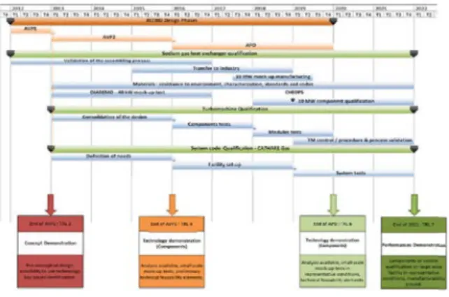
The main key dates of qualification of Gas PCS with associated TRL are shown in the following figure (Figure 10).
FIG. 10: Qualification projected plan
XIII. CONCLUSION
Studies conducted during the ASTRID conceptual design phase have led to progress in the choice of architectures and technologies for ASTRID gas PCS.
All these studies have increased significantly the Technology Readiness Level of ASTRID gas PCS and did not reveal any unacceptable points for its development.
NOMENCLATURE
ASTRID Advanced Sodium Technological Reactor for Industrial Demonstration AVP1 ASTRID Pre-conceptual Design Phase
(2010-2012)
AVP2 ASTRID conceptual Design Phase (2013-2015)
BOP Balance of Plant
CEA Commissariat à l’Energie Atomique et aux Energies Alternatives
HIP DB High Isostatic Pressure Diffusion Bonding
HP High Pressure
HTR High Temperature Reactor LP Low Pressure
PCS Power Conversion system PCHE Printed Circuit Heat Exchanger PFHE Plate-Fin Heat Exchanger PSHE Plate and Shell Heat Exchanger
RCC MRx Règles de Conception et de Construction des Matériels Mécaniques des Installations Nucléaires – Réacteurs Rapides et Réacteurs Expérimentaux (in French) – Design and Construction Rules applicable to equipment of Fast Reactors and Experimental Reactors
SFR Sodium-cooled Fast Reactor SG Steam Generator
SGHE Sodium Gas Heat Exchanger TRL
Technology readiness Level
REFERENCES
[1] F. GAUCHE; The French Prototype of 4th Generation Reactor: ASTRID; Annual meeting on nuclear technology, Berlin, May
17&18th; (2011).
[2] J. ROUAULT et al.; The ASTRID Project status and prospects at the beginning of the Basic Design Phase, Proceedings of ICAPP’16, San Francisco United-States, April 17-20, (2016)
[3] General recommendation for the project management specification -
http://www.bnae.asso.fr/fr/menu-normes/catalogue/rg-aero-menu
[4] G LAFFONT et al.; Astrid power conversion system based on steam and gas options; proceedings of ICAPP’2013, Jeju
Island, Korea, April 14-18, (2013)
[5] Ch. GALATI et al, “Preliminary Analysis of Flow Maldistribution in ASTRID Sodium-Gas Heat exchanger”; Proceedings of
ICAPP’16, San Francisco United-States, April 17-20, (2016)
[6] RCCMRx -
http://www.afcen.com/fr/publications/rcc-mrx