HAL Id: tel-01673838
https://tel.archives-ouvertes.fr/tel-01673838
Submitted on 1 Jan 2018HAL is a multi-disciplinary open access archive for the deposit and dissemination of sci-entific research documents, whether they are pub-lished or not. The documents may come from teaching and research institutions in France or abroad, or from public or private research centers.
L’archive ouverte pluridisciplinaire HAL, est destinée au dépôt et à la diffusion de documents scientifiques de niveau recherche, publiés ou non, émanant des établissements d’enseignement et de recherche français ou étrangers, des laboratoires publics ou privés.
electrospinning : application to tissue engineering
Salima Nedjari
To cite this version:
Salima Nedjari. Microstructuration of nanofibrous membranes by electrospinning : application to tissue engineering. Biomaterials. Université de Strasbourg, 2014. English. �NNT : 2014STRAE027�. �tel-01673838�
ÉCOLE DOCTORALE PHYSIQUE ET CHIMIE-PHYSIQUE
ICPEES Institut de Chimie Pour l’Energie, l’Environnement et la Santé
THÈSE
présentée par :Salima NEDJARI
Soutenue publiquement le : 21 octobre 2014
pour obtenir le grade de :
Docteur de l’Université de Strasbourg
DISCIPLINE: PHYSIQUE-CHIMIE
SPECIALITE
: BIOMATERIAUX
Microstructuration of nanofibrous
membranes by electrospinning:
Application to tissue engineering
Membres du jury:
M. Guy SCHLATTER Professeur, Université de Strasbourg
Directeur de Thèse
Mme Karen DE CLERCK Professeur, Université de Gent Rapporteur externe
M. Christophe EGLES Professeur, Université de Technologie de Compiègne Rapporteur externe
M. Luc AVEROUS Professeur, Université de Strasbourg
3
A Papa et Maman, mes parents bien-aimés, A ma grande soeur Fatiha chérie, A mes petits choux qui grandissent, A ma cousine Rachida, paix à son âme,
5
Remerciements
Mes travaux de thèse ont été effectués au sein de l’Institut de Chimie et Procédés pour l’Environnement, l’Energie et la Santé (ICPEES) UMR7515 et également au sein de l’unité de Médecine Nano-Régénérative U1109 de l’INSERM.
J’exprime une profonde gratitude et mes très sincères remerciements à Monsieur le Professeur Guy Schlatter, mon directeur de thèse. Je le remercie pour sa gentillesse, sa disponibilité et pour m’avoir si bien encadrée et guidée durant ces années de recherches. Je suis très heureuse d’avoir pu travailler avec lui et je pense avoir beaucoup appris à son contact. Il a su me transmettre son esprit passionné pour l’électrospinning et je l’en remercie sincèrement.
Je souhaite également remercier très sincèrement le Docteur Anne Hébraud pour m’avoir encadrée durant ma thèse et pour m’avoir appris tant de choses. Je la remercie pour sa gentillesse, sa disponibilité et les précieux conseils qu’elle m’a donnés.
J’adresse mes sincères remerciements aux membres du jury qui ont accepté d’évaluer mon travail de thèse :
Mme Karen De Clerck, professeur à l’Université de Gent, et Mr Christophes Egles, professeur à l’Université de Technologie de Compiègnes pour avoir accepté d’être de participer à mon jury de thèse en tant que rapporteurs externes.
Mr Luc Averous, professeur à l’Université de Strasbourg, pour avoir accepté de participer à mon jury de thèse en tant qu’examinateur.
Mme Anne Hébraud et Mme Nadia Benkirane-Jessel pour avoir accepté de participer à mon jury de thèse en tant que membres invités.
Je souhaiterai particulièrement remercier les partenaires du projet NeoTissage, projet dans lequel s’inscrit ma thèse.
Tout d’abord, je remercie très sincèrement le Docteur Nadia Benkirane-Jessel de l’INSERM pour m’avoir accueilli au sein de son équipe, pour ses encouragements et ses précieux conseils.
Je remercie très chaleureusement le Docteur Ségolen Geffray de l’IRMA, pour son incroyable gentillesse et sa bonne humeur. Son aide et ses explications m’ont étaient très précieux pour ma thèse.
6
Enfin, je remercie particulièrement le Docteur Sandy Eap de l’INSERM pour notre très fructueuse et très agréable collaboration. Je la remercie pour son écoute et son aide dans mes travaux de recherches.
Je tiens également à adresser mes sincèrement remerciements à Mr Nabyl Khenoussi, Maitre de Conférences à l’ENSISA pour m’avoir fait découvrir les nanofibres, pour sa gentillesse et pour m’avoir encouragée tout au long de ma thèse.
Ensuite, je souhaiterai adresser mes profonds remerciements au personnel technique de l’ICPEES sans qui je n’aurai pas pu avancer aussi bien dans ma thèse : Sabine Siegwald, Romain Bernard (IPCMS), Christophe Mélart, Christophe Sutter et Thierry Djekkriff. Je suis très reconnaissante pour toute l’aide qu’ils m’ont apporté et je l’ai remercie pour l’incroyable bonne humeur dans laquelle on a travaillé.
Je remercie également Chheng Ngov, Sébastien Gallet et Catherine Kientz pour leur gentillesse, leur aide et leur disponibilité.
Je remercie également Badi Triki pour les très bons moments qu’on a passés ensemble au laboratoire d’électrospinning.
Au sein de l’ICPEES, je remercie très chaleureusement l’ensemble des doctorants, post-doctorants, stagiaires que j’ai pu rencontrer et qui m’ont apporté beaucoup de joie durant ces années de thèse: Allan, Anna, Bilal, Bruno, Camille, Cannan, Cédric, Dambarudhar, Deepak, Dhriti, Dias, François-Xavier, Ikram, Inès, Jon, Julianna, Julianno, Lukas, Marie, Marina, Matthieu, Nancy, Rigoberto, Rogério, Rouba, Simon, Shugai, Stéphanie, Stéphane, Thibaud, Victor, Wei et Yuefengh.
Au sein de l’unité de médecine régénérative U1109, je remercie Sabine Bopp-Kuchler, Arielle Ferrandon, Tunay, Laeticia, et Stéphanie pour leur bonne humeur.
Je remercie également mes amies : Sarah, Jessica et Nour. Merci de m’avoir motivée pendant toutes ces années.
7
Enfin, je remercie ceux qui m’ont toujours encouragée et soutenue durant toutes ces années d’études et que j’aime très fort : mes parents Abdelkader Nedjari et Khedouja Nedjari pour leur amour et leur générosité. Et également un immense merci à ma grande sœur Fatiha Nedjari que j’aime très très fort : merci infiniment pour ton amour inconditionnel et pour avoir si bien veillé sur moi.
9 Titre français :
Micro-structuration de membranes nanofibreuses par électrospinning : application à l’ingénierie tissulaire
Cette thèse de doctorat a été rédigée en utilisant, pour chaque chapitre, le format habituellement adopté dans les articles scientifiques paraissant dans des revues à comité de lecture. L’indulgence du lecteur est ainsi sollicité pour les répétitions et redites inhérentes à la forme de rédaction choisie.
Le présent mémoire de thèse a été rédigé en langue anglaise, conformément à l’autorisation délivrée par Monsieur le Professeur Éric WESTHOF, professeur des Universités à l’université de Strasbourg, et vice-président de l’université de Strasbourg, chargé de la recherche et de la formation doctorale, le 08 juillet 2008.
11
REMERCIEMENTS ... 5
RESUME ………15
ABSTRACT
………..17
ABBREVIATIONS, ACRONYMS AND SYMBOLS ... 19
GENERAL INTRODUCTION ... 21
CHAPTER 1:
AN INTRODUCTION TO ORGANIZED NANOFIBERS :
FROM 1D TO 3D ... 35
1. ELECTROSPINNING PROCESS ... 37
1.1 Electrospinning theory ... 37
1.2 Electrospinning setup ... 39
1.3 Electrospinning parameters ... 40
2. ORGANIZED ASSEMBLY OF ELECTROSPUN NANOFIBERS: FROM 1D TO 3D ... 48
2.1 Fiber Alignment ... 49
2.1.1 Electrostatic Forces ... 49
2.1.2 Magnetic Forces ... 53
2.1.3 Mechanical forces ... 54
2.2 2D Patterned Nanofibrous Membranes ... 59
2.2.1 2D Composites formed from 1D aligned fibers ... 59
2.2.2 Complex 2D patterned membranes by precise control of electrostatic forces ... 60
2.2.3 Self-assembly of electrospun fibers ... 64
2.3 Towards 3D Nanofibrous Constructs ... 69
2.3.1 Specific electrospinning processes for 3D constructs ... 69
2.3.2 3D Cm-thick scaffolds from self-assembled electrospun fibers ... 70
2.4 Conclusions of the structuration ... 73
12
CHAPTER 2:
MONOCOMPONENT 2D AND 3D ARCHITECTURED
NANOFIBROUS SCAFFOLDS FOR BONE REGENERATION ... 77
1. INTRODUCTION ... 79
2. MATERIALS AND METHODS ... 80
2.1 Photolithographic processes ... 80
2.1.1 Principle ... 80
2.1.2 Main steps in photolithography process used during this work. ... 81
2.2 Polymers for bone tissue engineering applications ... 84
2.2.1 PCL ... 85
2.2.2 PLA ... 86
3. ELECTROSPINNING OF PCL AND PLA ... 89
3.1 Electrospinning of PCL ... 89
3.2 Electrospinning of PLA ... 93
4. 2DSTRUCTURATION ... 96
4.1 Electrospinning on block collectors ... 96
4.2 Electrospinning on honeycomb micropatterned collectors ... 100
Electrospun Honeycomb as Nests for Controlled Osteoblast Spatial Organization ... 100
4.2.1 Introduction ... 101
4.2.2 Experiments ... 103
4.2.3 Results and Discussion ... 106
4.2.4 Conclusions ... 116
4.2.5 Supporting informations ... 117
5. 3D STRUCTURATION ... 122
5.1 Introduction... 122
5.2 Materials and Methods ... 123
5.2.1 Fabrication of honeycomb micropatterned collector ... 123
5.2.2 Electrospinning of 3D Scaffold ... 123
5.2.3 Scanning electron microscopy (SEM) and X-ray microcomputed tomography ... 124
5.3 Results and Discussions ... 124
5.4 Conclusions ... 128
13
6. CONCLUSIONS OF THE CHAPTER TWO ... 131
CHAPTER 3:
COMPOSITE 2D AND 3D ARCHITECTURED
NANOFIBROUS SCAFFOLDS... 134
1. INTRODUCTION ... 136
2. ELECTROSTATIC TEMPLATE-ASSISTED DEPOSITION OF MICROPARTICLES ON ELECTROSPUN NANOFIBERS: APPLICATION TO THE FABRICATION OF BIOCHIPS FOR THE SCREENING OF COMPOSITE MICROSTRUCTURED MATERIALS FOR BONE REGENERATION ... 137
2.1 Introduction... 137
2.2 Electrostatic template-assisted deposition of microparticles on electrospun nanofibers ... 140
2.2.1 Electrospraying of hydroxyapatite ... 140
2.2.2 Electrospinning and cross-linking of Alginate nanofibers ... 142
2.2.3 Selected experimental conditions ... 147
2.2.4 Controlled deposition of hydroxyapatite particles on electrospun fibers ... 147
2.3 Biochip by electrospinning and electrospraying: application for the screening of PCL/HA microstructured composites for bone regeneration ... 150
2.3.1 Protocols ... 152
2.3.2 Results and discussions ... 153
2.4 Screening of composite fibrous structured materials for bone regeneration: preliminary results .. 161
2.4.1 Protocols for biological characterization ... 161
2.4.2 Results and discussion ... 163
2.5 Conclusions ... 170
3. 3D COMPOSITE ELECTROSPUN SCAFFOLD WITH CONTROLLED PORE SIZE ... 172
3.1 Introduction... 172
3.2 Experimental Section ... 174
3.2.1 Materials ... 174
3.2.2 Fabrication of the collectors ... 174
3.2.3 Electrospinning / electrospraying ... 175
3.2.4 SEM analysis ... 175
3.2.5 Mechanical characterization ... 176
14
3.4 Conclusion ... 188
4. CONCLUSIONS OF THE CHAPTER THREE ... 189
GENERAL CONCLUSION AND PERSPECTIVES ... 191
CONCLUSIONS AND PERSPECTIVES ... 192
REFERENCES ………199
15
Résumé
L’objectif de cette thèse était de développer de nouveaux biomatériaux nanofibreux architecturés (2D ou 3D) grâce à la méthode d’électrospinning puis d’étudier l’influence de ces structures nanofibreuses sur le comportement des cellules osseuses. L’électrospinning est une technique qui permet d’obtenir des nanofibres en projetant sous l’action d’un champ électrique intense une solution de polymère sur un collecteur. Le jet de la solution de polymère, émanent de l’émetteur (une aiguille métallique soumis à une tension de plusieurs kV), subit des mouvements de fouet violents qui conduisent à la réduction du diamètre et à l’évaporation du solvant. Les nanofibres sont alors généralement disposées aléatoirement sous forme de mats (ou scaffolds). Ces scaffolds trouvent des applications en ingénierie tissulaire grâce à leur structure mimant la matrice extracellulaire des tissus vivants. Toutefois, il a été montré que lorsque le collecteur est micro-structuré, il est alors possible de contrôler l’organisation des fibres lors de leur dépôt grâce à la perturbation locale du champ électrique au voisinage de la surface du collecteur. Ces collecteurs architecturés jouent ainsi le rôle de « templates » électrostatiques. C’est dans ce contexte que s’est inscrit ce sujet de thèse.
Dans un premier temps, nous avons développé des scaffolds 2D nanofibreux monocomposants en forme de nids d’abeilles grâce à l’utilisation d’un collecteur micro-structuré en nids d’abeilles lors du procédé d’électrospinning. Ces scaffolds ont été développés à partir de deux biopolyesters le poly(ε-caprolactone) (PCL) ou le poly(lactic acid) (PLA). Nous avons prouvé que la morphologie des nanofibres de PCL (distribution bimodale du diamètre des fibres) conduisait à un scaffold présentant un relief beaucoup plus marqué alors qu’avec les fibres de PLA, qui présentent une distribution monomodale du diamètre des fibres, les scaffolds obtenus sont beaucoup plus plats. Puis nous avons montré qu’il est possible de contrôler l’organisation spatiale de cellules osseuses de type MG-63, des ostéoblastes, en jouant sur le relief et l’architecture du scaffold.
Puis, nous avons cherché à développer des matériaux 3D en utilisant des collecteurs micro-structurés afin d’ouvrir de nouvelles voies pour l’élaboration de matériaux de comblement pour la régénération osseuse. Nous avons démontré qu’en couplant la micro-structuration des nanofibres de PCL (par l’utilisation d’un collecteur en nid d’abeilles lors du procédé d’électrospinning) avec les propriétés d’auto-assemblage du PCL, nous pouvions élaborer de nouveaux scaffolds nanofibreux 3D ayant la particularité de présenter des pores de tailles contrôlées ainsi qu’un gradient de porosité dans l’épaisseur du scaffold.
16
Puis nous nous sommes intéressés à l’élaboration de membranes composites micro-structurées 2D et 3D. En couplant le procédé d’électrospinning avec le procédé d’électrospraying sur des collecteur micro-structurés, nous avons démontré que nous pouvions déposer de manière contrôlée les particules spécialement sur les murs des nids d’abeilles grâce notamment à la présence d’une très fine couche de fibres électrospinnées au préalable sur le collecteur. Cette fine couche de nanofibres joue le rôle de « template électrostatique » pour le dépôt des particules.
Nous avons ensuite appliqué cette technique pour développer des membranes composites nanofibreuses bicouches à base de nanofibres de PCL et de microparticules d’hydroxyapatite (HA). Ces membranes composées de 21 microarchitectures différentes (barres, plots, hexagones, labyrinthe) ont ensuite été intégrées dans des mini plaques de culture cellulaire, formant ainsi un nouveau type de biopuce, pour le screening d’architectures nanofibreuses. En effet, ces biopuces appelées biochip ont prouvé qu’elles permettaient de réaliser le screening de microarchitectures nanofibreuses composites afin d’identifier la plus pertinente pour la régénération osseuse. Il s’est avéré que la structure HA hexagonale (avec un diamètre moyen de 300 µm) ainsi que les structures HA circulaires (avec un diamètre moyen 150 µm environ) sont celles qui améliorent le mieux le processus de minéralisation des cellules osseuses.
Enfin, nous avons montré qu’il est possible d’élaborer des scaffolds composites 3D en combinant simultanément l’électrospinning de nanofibres et l’électrospraying de particules sur des collecteur micro-structurés en nid d’abeilles. Il est possible de contrôler la taille des pores cylindriques de ces composites 3D de quelques dizaines de microns à quelques centaines de microns en changeant la taille du nid d’abeilles du collecteur.
17
Abstract
The aim of this thesis was to develop new architectured nanofibrous biomaterials (2D or 3D) using the electrospinning method and to study the influence of these nanofibrous structures on bone cells behaviors. Electrospinning is a technique allowing the production of nanofibers by projecting, under the action of a strong electric field, a polymer solution on a collector. The jet of the polymer solution, emitted from a metalic needle subjected to a voltage of several kV, undergoes strong whipping movements, resulting in the evaporation of the solvent and the reduction of the diameter of the nanofiber. The nanofibers are generally randomly deposited and form mats or scaffolds. These scaffolds are interesting for tissue engineering applications because of their structure mimicking the extracellular matrix of living tissues. However, it has been shown that when the collector is microstructured, it is possible to control the organization of the fibers during their deposition through the local perturbation of the electric field at the vicinity of the surface of the collector. These micropatterned collectors act as "electrostatic templates".
First, 2D honeycomb nanofibrous scaffolds were elaborated using micropatterned honeycomb collectors during the electrospinning process. These scaffolds were made either with poly(ε-caprolactone) (PCL) or poly(lactic acid) (PLA). We showed that the morphology of the PCL nanofibers (bimodal distribution of the fiber diameter) led to a scaffold with a strong relief. Despite, with PLA fibers which presented a monomodal distribution of the fiber diameter, the obtained scaffolds were much flatter. It was possible to control the spatial organization of bone-like cells MG-63 (osteoblasts), playing on the relief and the architecture of the scaffold.
Subsequently, 3D materials were elaborated using micropatterned collectors in order to open new paths for the development of filling materials for bone regeneration. Microstructuration of PCL nanofibers (by the use of micropatterned honeycomb collector during the electrospinning process) coupled with the self-assembling properties of the PCL lead to the development of new 3D nanofibrous scaffolds, with controlled pore size and porosity gradient in the thickness of the scaffold.
Afterwards, micropatterned composite 2D and 3D membranes were elaborated. By coupling the process of electrospinning with the process of electrospraying on micropatterned collector, we demonstrated that we can deposit the particles in a controlled way, especially on the walls of honeycomb patterns thanks to the presence of a thin fiber layer first deposited on
18
the collector. This thin nanofiber layer plays the role of an "electrostatic template" for the particles deposition.
Thereafter, this technique was applied to develop bilayers composite nanofibrous membranes containing PCL nanofibers and hydroxyapatite (HA) microparticles. These membranes consisted of 21 different microarchitectures (bars, blocks, hexagons, maze) were then incorporated into a small cell culture plate, thereby forming a new type of biochip for the screening of nanofibrous architectures. Indeed, these biochips allowed the screening of nanofibrous microarchitectures to identify the most relevant for bone regeneration. It turned out that the HA hexagonal structures (with an average diameter of 300 microns) and circular HA structures (with an average diameter of 150 microns) are the structures that enhance the most the mineralization process of bone cells.
Finally, by combining simultaneously electrospinning nanofibers and electrospraying particles on micropatterned honeycomb collector, 3D composite scaffolds were elaborated. It was possible to control the size of cylindrical pores of these 3D composite from tens to hundreds of microns by changing the size of the honeycomb patterns of the collector.
19
Abbreviations, acronyms and symbols
AA Acetic Acid
Al Alginate
BSPII Bone SialoProtein II
C Concentration
Ca(OH)2 Calcium Hydroxyde
Ca10(PO4)6(OH)2 Hydroxyapatite
CHCl3 Chloroform
CaCl2 Calcium Chloride
DCM Dichloromethane
DMF Dimethylformamide
DW Deionized Water
EtOH Ethanol
FA Formic Acid
FDA Food and Drug Administration
GTA Glutaraldehyde
HA Hydroxyapatite
HFIP Hexafluoropropan-2-ol
H3PO4 Orthophosphoric acid
OCN Osteocalcin
20
PCL Poly(ε-caprolactone)
PDMS Polydimethylsiloxane
PEG Poly(ethylene glycol)
PEO Polyethylene Glycol
PFA Paraformaldehyde
PGA Polyglycolic Acid
PLA Poly(lactic acid)
PMMA Poly(methyl methacrylate)
PS Polystyrene
PVA Polyvinyl alcool
SEM Scanning Electron Microscopy
TFE 2,2,2-trifluoroethanol
Tg Glass Temperature
THF Tetrahydrofuran
Tm Melting point
21
23 Context:
Currently, global population is ageing and new health challenges have emerged. Indeed, while in the past, people were dying of infectious diseases, nowadays, the number of chronic diseases is increasing and has become responsible of health loss and death. Contrary to infectious diseases which are cured by antibiotics, the chronic diseases should be cured by regenerative approaches [1].
Among these chronic diseases, bone diseases represent a big challenge due to apparent inability of bone to self-repair. Indeed, there is no effective therapy available and patients can only be helped by surgical joint replacement. An inherent major concern is the limited availability of autografts, which significantly reduces the number of treatable defects. Therefore, tissue engineering for bone regeneration appears as the most promising alternative.
The term “Tissue engineering” was firstly used by Dr. Fung from California University during the National Science Foundation Meeting in 1987 [2]. The official definition dates to 1988 and was published in 1988 by Skalak and Fox, after the Tissue engineering meeting held in USA this year [3].
Tissue engineering refers to an “interdisciplinary field that applies the principles of engineering and life sciences toward the development of biological substitutes that restore, maintain or improve tissue function” [4]. In 1993, Langer and Vacanti introduced three different strategies of tissue engineering [3] (Figure 1):
(a) The development of cell therapy : infusion of cells at the lesion place (like stem cells) (b) The development of specific molecules (such as growth factor, small molecules which
promote several effects on the cells)
(c) The development of scaffold or matrices, which are placed at the lesion, and which enhances and promotes the regeneration process.
While research has been made about cells and specific molecules, the degree of success of tissue engineering is still highly dependent on the properties of the scaffold.
24
Figure 1: Tissue engineering strategies: As proposed by Langer and Vacanti [5, 6], tissue engineering can be performed by different approaches. Combining cells, scaffolds and signaling
molecules can be the best association for tissue regeneration.
It is now very important to develop efficient biomaterials for bone regeneration. Efforts have to be made on the Achilles’ hill of tissue engineering: the scaffold. The main challenge relies upon the design of ideal scaffold/ synthetic matrices that can mimic the structure and biological functions of the natural extracellular matrix.
The scaffold plays a key role as it must guide the cell growth, allow the synthesis of extracellular matrix and other biological molecules and facilitate the formation of new functional tissue. There are several basic and important requirements for the design of bone regeneration scaffold. It should:
(a) Be biocompatible : the scaffold should not be rejected when it is put at the lesion place
(b) Be biodegradable : it should degrade with the same speed (rate) than the new tissue is growing
(c) Present good mechanical properties, near to the native mechanical properties of the native organ
(d) Have a good porosity, which will allow nutrients intakes and cell penetration deeper in the scaffold
25
(e) Present functional character in order to enhance bone cells-scaffold interactions such as adhesion, growth, migration, differentiation function, and bio-mineralization. (f) Mimic well the structure of the native tissue
It is also well known that because the extracellular matrix is made of collagen nanofibers, the scaffold must show specific fibrous morphology. Besides, one of the most promising techniques to develop nanofibrous scaffold for tissue engineering is electrostatic spinning also called electrospinning.
Electrospinning was invented and patented in 1902 by Cooley [7] and Morton [8]. This technology allows the production of nanofibers by the projection of a polymer solution under a high electrical field in order to produce nanofibers with a diameter ranging from few tens of nm to few microns.
Electrospinning was patented in 1934 by Formhals [9]. However, due the incapacity to observe the obtained nanofibers, scientists were not interested by this technique.
It is only in the 1990’s that electrospinning was rediscovered. Renecker et al. showed that electrospun fabrics are promising materials due to their high surface to volume ratio and their capability to mimic natural tissues [10, 11].
Furthermore, this technique is applicable with any kind of polymer which can be dissolved in a solvent or molten by heating. Therefore, electrospinning can be used in many domains such as filtration [12, 13], protective clothes [14, 15], environmental engineering [16, 17], electronics [18, 19], and of course biomedical [20-22] and tissue engineering [23, 24]. For all these reasons, electrospinning presents a growing interest for researchers around the world (Figure 2).
Figure 2: Plot of annual research publications concerning electrospinning studies. Search data from http://www.scopus.com, years 2000–2014, using “electrospinning” or “electrospun,” as
article title, abstract, or keywords.
0 1000 2000 3000 4000 5000 6000 7000 2000 2001 2002 2003 2004 2005 2006 2007 2008 2009 2010 2011 2012 2013 2014 Publi ca tion Number Year
26 Structuration of electrospun nanofibers:
Many tissues or organs (heart, nerves, and skin) have a native complex structure and bones are among them. Effective regeneration process of these complex tissues could only be possible with scaffolds that are able to mimic as closely as possible the native structure of these tissues.
Electrospinning is a very interesting technique in the field of tissue regeneration due to its capability to structure the nanofibers from one dimension to three dimensions. Indeed, while with a classical electrospinning setup, fibers are generally collected in a random way on the collector (generally an aluminum foil), it is possible to structure the electrospun mat by just changing the nature of the collector. Researchers have developed different kinds of collectors in order to organize the nanofibers from simply aligned nanofibers to complex three dimensional nanofibrous scaffolds [25]. Now, architectured electrospun scaffolds with fibrous/ porous/ roughness morphology (from several nm to hundreds µm length scales) can be obtained. They are used in different fields of tissue engineering. Thanks to in vitro an in
vivo studies, the efficiency of these electrospun architectured scaffolds is evaluated. Despite,
very often, the influence of the electrospun scaffold morphology on cells behaviors is not very well explained and understood.
This thesis seeks to elaborate and to study new kinds of micropatterned scaffolds obtained by electrospinning process for bone regeneration applications. The control of the architecture of electrospun scaffolds is explained. The influence of different micropatterned electrospun structures on osteoblast cells behaviors such as spatial organization and mineralization is studied.
The first chapter of this work is a review of all the methods existing to organize the nanofibers from 1D to 3D dimensions with the electrospinning process. The effect of the different forces acting on the fiber structuration during the process is explained.
In the second chapter, the elaboration of monocomponent micropatterned electrospun scaffold is presented. The first part of this chapter deals with 2D monocomponent micropatterned scaffolds. Thanks to photolithographic processes, micropatterned collectors were obtained (block collector and honeycomb collector). Two kinds of biopolyesters were then tested for the fabrication of the electrospun membranes. After optimization of the electrospinning parameters, honeycomb electrospun scaffolds were elaborated either with poly(ε-caprolactone) (PCL) either with poly(lactic acid) (PLA). First, the effect of the fiber morphology on the morphology at the scaffold’s length scale was discussed. Then, the
27
influence of honeycomb structure of the electrospun scaffold on osteoblast cells organization was showed. In the second part of the Chapter 2, elaboration of 3D monocomponent micropatterned scaffolds is presented. We demonstrate that by using honeycomb collector and the self-assembling properties of fibers, we were able to fabricate a new kind of 3D electrospun scaffold. The mechanism of formation of such 3D electrospun scaffold is explained. This scaffold has the particularity to present porous columns and porosity gradient with controlled pore size, which could be useful for bone regeneration applications.
The third chapter deals with composites micropatterned electrospun membranes elaborated with nanofibers (PCL, alginate or PLA) and microparticles (hydroxyapatite or poly(ethylene oxide) (PEO)). In the first part of this chapter, we present a new kind of 2D composite electrospun microstructured membrane. First, we explained the "electrostatic template effect" leading to the local controlled deposition of particles on an electrospun thin membrane deposited on a micropatterned collector. This kind of composite membranes were used in a new device called a biochip. The biochip was dedicated for screening application for bone regeneration. This device was made for testing different nanofibrous structures at the same time. It was developed in order to find quickly which kind of architecture of the nanofibrous membranes can induce the best bone regeneration process. Therefore, a biochip was an on-chip small cell culture plate with 21 different wells. In each well, a specific architecture made by PCL nanofibers and hydroxyapatite microparticles is included. The smaller size of the biochip and the screening of the different micropatterned composite electrospun membranes (located in each well) made this device a new tool for rapid diagnosis in bone tissue regeneration. On the second part of the third chapter, we present new kind of 3D composite micropatterned membrane. These 3D composite construct were elaborated by alternately electrospraying and electrospinning onto a honeycomb micropatterned collector. We showed that these scaffolds presented cylindrical pores with an internal diameter that could be tuned precisely from tens to hundreds microns. Tensile measurements showed good mechanical properties of these scaffolds, promoting their use in tissue regeneration applications.
28 Contexte:
Actuellement, la population mondiale vieillit de plus en plus, et de nouveaux défis de santé ont vu le jour. En effet, alors que dans le passé, les gens mouraient de maladies infectieuses, de nos jours, le nombre de maladies chroniques augmente et est devenu le principal facteur de décès de la population. Contrairement aux maladies infectieuses qui sont soignées par la prise d’antibiotiques, les maladies chroniques doivent être soignées par des approches régénératives [1].
Parmi ces maladies chroniques, les maladies osseuses représentent un important défi en raison de l'incapacité apparente de l'os à s’auto-réparer. En effet, il n’existe aucun traitement efficace disponible à ce jour et les patients ne peuvent être aidés que par des arthroplasties chirurgicales. Une des préoccupations majeures qui en découle est la disponibilité limitée des autogreffes, ce qui réduit considérablement le nombre de patients traitables. Par conséquent, l'ingénierie tissulaire apparaît comme la solution la plus prometteuse pour la régénération osseuse.
Le terme «ingénierie tissulaire » a d'abord été utilisé par le Dr Fung de l'Université de Californie lors de l'Assemblée National Science Foundation en 1987 [2]. La définition officielle remonte à 1988 et a été publié en 1988 par Skalak et Fox, après la conférence sur l’ingénierie tissulaire tenue aux Etats-Unis cette même année [3].
L'ingénierie tissulaire se réfère à un "domaine interdisciplinaire qui applique les principes d'ingénierie et de sciences de la vie afin de développer des substituts biologiques qui peuvent restaurer, maintenir ou améliorer la fonction des tissus" [4]. En 1993, Langer et Vacanti introduisent trois stratégies différentes en ingénierie tissulaire [3] (Figure 1):
(a) Le développement de la thérapie cellulaire: injection de cellules à l'endroit de la lésion (comme des cellules souches par exemple)
(b) La mise au point de molécules spécifiques (tels que des facteurs de croissance, des petites molécules qui favorisent différents effets sur les cellules)
(c) Le développement de scaffolds ou matrices, qui sont mis en place au niveau de la lésion, et qui améliorent et favorisent le processus de régénération.
Bien que beaucoup de recherche ait été faite au sujet de la thérapie cellulaire et également au sujet de l’élaboration de nouvelles molécules spécifiques, le degré de succès de l'ingénierie tissulaire dépends encore très fortement des propriétés du scaffold qui est introduit au niveau de la lésion.
29
Figure 1 : Les stratégies en ingénierie tissulaire: Comme proposé par Langer et Vacanti [ 5 , 6 ], l'ingénierie tissulaire peut être effectuée par différentes approches. Combiner à la fois la thérapie cellulaire, l’utilisation de scaffolds ainsi que des molécules spécifiques peut représenter
la meilleure association pour parfaire la régénération des tissus.
Il est maintenant très important de développer des biomatériaux efficaces pour la régénération osseuse. Des efforts doivent être faits en ce qui concerne le talon d’Achille de l’ingénierie tissulaire, à savoir le scaffold. Le principal défi repose sur la conception du scaffold idéal / des matrices synthétiques qui peuvent imiter à la fois la structure et les fonctions biologiques de la matrice extracellulaire naturelle.
Le scaffold joue un rôle essentiel car il doit promouvoir la croissance des cellules, permettre la synthèse de la matrice extracellulaire et d'autres molécules biologiques et également faciliter la formation d'un nouveau tissu fonctionnel. Il y a plusieurs exigences fondamentales et nécessaires pour la conception d’un scaffold dédié à la régénération osseuse. Il doit :
(a) Être biocompatible: le scaffold ne doit pas être rejeté quand il est mis en place au niveau de la lésion.
(b) Être biodégradable: le scaffold doit se dégrader à la même vitesse que le nouveau tissu qui est en train de se former.
(c) Présenter de bonnes propriétés mécaniques, proche des propriétés mécaniques de l'organe qu’il vise à régénérer.
30
(d) Avoir une bonne porosité, ce qui permettra l'apport de nutriments et une pénétration cellulaire plus profonde dans le scaffold.
(e) Présenter certains propriétés spécifiques afin d’améliorer les intéractions cellules osseuses –scaffold telle que l’adhésion, la croissance, la migration, la différenciation et la bio-minéralisation.
(f) Bien imiter la structure native du tissu.
Il est également bien connu que la matrice extracellulaire est constituée de nanofibres de collagène. Afin d’optimiser le processus de régénération, le scaffold doit présenter une morphologie fibreuse qui tend à mimer la structure fibreuse de la matrice extracellulaire. L’une des techniques les plus prometteuses pour développer des scaffolds nanofibreux pour l'ingénierie tissulaire est le filage électrostatique également appelé électrofilage ou électrospinning.
L’électrospinning a été inventé et breveté en 1902 par Cooley [7] et Morton [8]. Cette technologie permet la production de nanofibres par la projection d'une solution de polymère sous un champ électrique élevé afin de produire des nanofibres ayant un diamètre allant de quelques dizaines de nm à quelques microns.
L’électrospinning a été breveté en 1934 par Formhals [9]. Toutefois, en raison de l'incapacité des scientifiques à observer les nanofibres obtenues, ils ne se sont pas intéressés à cette technique.
Ce n’est que dans les années 1990 que l’électrospinning a été redécouvert. Renecker et al. ont montré que les non-tissés obtenus par électrospinning sont des matériaux prometteurs en raison de leur rapport élevé surface / volume ainsi que leur capacité à mimer les tissus vivants [10, 11].
De plus, cette technique peut être appliquée à tout type de polymère qui peut être dissous dans un solvant ou fondue par chauffage. Par conséquent, l’électrospinning peut être utilisé dans de nombreux domaines tels que la filtration [12, 13], les vêtements de protection [14, 15], le génie environnemental [16, 17], l'électronique [18, 19], et bien sûr le domaine biomédical [20-22] et l'ingénierie tissulaire [23, 24]. Pour toutes ces raisons, l’électrospinning présente un intérêt croissant pour les chercheurs du monde entier (Figure 2).
31
Figure 2 : Nombre de publications annuels concernant les études portant sur l’électrospinning Recherche des données sur http://www.scopus.com, années 2000-2014, en utilisant les termes
« electrospinning » ou « electrospun », comme titre d’article, de résumé, ou de mots-clés.
Structuration des nanofibres obtenues par électrospinning :
Beaucoup de tissus ou d'organes (tels que le cœur, les nerfs et la peau par exemple) présentent naturellement une structure complexe. Les os sont également des tissus naturellement structurés. Le processus de régénération de ces tissus ne peut être efficace que si les scaffolds employés sont capable de mimer le plus fidèlement possible la structure native de ces tissus.
L’électrospinning est une technique très intéressante dans le domaine de la régénération des tissus en raison de sa capacité à permettre la structuration de nanofibres d’une dimension à trois dimensions. En effet, en utilisant un montage d’électrospinning classique, les fibres sont généralement collectées de manière aléatoire sur le collecteur (qui est en général une feuille d'aluminium). Cependant il est possible de structurer le tapis de nanofibres en changeant simplement la nature du collecteur. Les chercheurs ont développé différents types de collecteurs afin d'organiser les nanofibres : ils ont pu réaliser à la fois des fibres simplement alignées (1D) jusqu’à l’élaboration de scaffolds 3D nanofibreux complexes [25]. De nos jours, des scaffolds présentant des morphologies à la fois nanofibreuses, poreuses et ayant une rugosité de surface ont pu être obtenus. Ils sont utilisés dans différents domaines de l'ingénierie tissulaire. Grâce aux études in vitro et in vivo, l'efficacité de ces scaffolds architecturés obtenus par électrospinning a pu être évaluée. Cependant, très souvent, l'influence de la morphologie du scaffold nanofibreux sur les comportements cellulaires n’est pas bien expliquée et pas bien comprise par les chercheurs.
32
Cette thèse vise à élaborer et à étudier de nouveaux types de scaffolds micro-structurés obtenus par le procédé d’électrofilage (ou électrospinning) pour des applications en régénération osseuse. Le contrôle de l'architecture des scaffolds nanofibreux est expliqué. L'influence des différentes structures nanofibreuses sur les comportements des cellules osseuses (telles que l'organisation spatiale et la minéralisation des ostéoblastes) est étudié.
Le premier chapitre de ce travail recense toutes les méthodes existantes pour organiser les nanofibres d’une dimension à trois dimensions (1D à 3D) avec le processus d'électrospinning. L'effet des différentes forces agissant sur la structuration de la fibre pendant le procédé est expliqué.
Dans le deuxième chapitre, l'élaboration de scaffolds micro-structurés nanofibreux monocomposants est présentée. La première partie de ce chapitre traite des scaffolds 2D monocomposants structurés. Grâce aux procédés de lithographie, des collecteurs micro-architecturés ont été obtenus (des collecteurs plots et des collecteur en nid d'abeilles). Deux types de biopolyesters ont ensuite été testés pour la fabrication des membranes nanofibeuses. Après optimisation des paramètres d'électrofilage, les scaffolds en nid d’abeilles ont été élaborées soit avec du poly (ε-caprolactone) (PCL), soit avec du poly (acide lactique) (PLA). Premièrement, l'effet de la morphologie de la fibre sur la morphologie à l'échelle du scaffold a été discuté. Ensuite, l’influence de la structure en nid d'abeilles du scaffold nanofibreux sur l’organisation spatiale des cellules osseuses a été étudiée. Dans la deuxième partie du chapitre 2, l'élaboration de scaffolds 3D monocomposant micro-structuré est présenté. Nous démontrons qu’à l'aide d’un collecteur en nid d'abeilles et grâce aux propriétés d'auto-assemblage des fibres de PCL, nous avons été en mesure de fabriquer un nouveau type de scaffold 3D par électrospinning. Le mécanisme de formation de ces scaffolds 3D est expliqué. Ces scaffolds ont la particularité de présenter des colonnes poreuses avec une taille de pores contrôlée et un gradient de porosité dans l’épaisseur du scaffold, ce qui pourrait être très utile pour les applications en régénération osseuse.
Le troisième chapitre traite des membranes composites micro-structurées élaborées à partir de nanofibres (PCL, alginate ou PLA) et de microparticules (hydroxyapatite ou poly (oxyde d'éthylène) (PEO)). Dans la première partie de ce chapitre, nous présentons un nouveau type de membrane composite 2D micro-structurée. Tout d'abord, nous expliquons l’effet de « template » électrostatique d’une fine membrane de nanofibres (électrospinnée sur un collecteur micro-structuré) sur le dépôt contrôlé local de particules. Ce type de membranes composites ont été utilisés par la suite dans un nouveau type de biopuce appelé biochip. Le biochip a été conçu pour réaliser du screening dans le domaine de la régénération osseuse. Ce
33
dispositif permet de tester différentes structures nanofibreuses en même temps. Il a été développé dans le but de trouver rapidement quel est le type d’architecture nanofibreuse qui permet d’induire le meilleur processus de régénération osseuse. De ce fait, le biochip est une mini plaque de culture cellulaire constituée de 21 puits différents. Dans chaque puit se trouve une membrane composite nanofibreuse faite de nanofibres de PCL et de microparticules d’hydroxyapatite. Dans chaque puit, la membrane présente une architecture différente. La taille réduite de ce biochip et le fait qu’il permette de tester un grand nombre de structures nanofibreuses en même temps ont fait de ce dispositif un nouvel outil de diagnostic rapide dans le domaine de la régénération du tissu osseux.
Dans la deuxième partie du troisième chapitre, nous présentons nouveau type de membrane 3D composite micro-structurée. Ces scaffolds 3D composites ont été élaborés en réalisant alternativement l’électrospinning de nanofibres et l’électrospraying de microparticules sur des collecteurs micro-structurés en nid d’abeilles. Nous avons montré que ces scaffolds présententt des pores cylindriques avec un diamètre intérieur qui peut être de quelques dizaines à quelques centaines de microns. Des mesures en traction ont permis de mettre en évidence les bonnes propriétés mécaniques de ces scaffolds, favorisant ainsi leur utilisation dans des applications de régénération tissulaire.
35
Chapter 1: An introduction
to organized nanofibers :
37
1. Electrospinning process
1.1 Electrospinning theory
Electrospinning is a way of obtaining nanofibers that can be used with a wide variety of polymers. Applying the electrostatic force for drawing a pendant droplet of polymer solution, to form fibers in sub-micron scale, is the electrospinning theory. In fact, the polymer solution is placed in a syringe connected to a needle. An automatic pump feeds the polymer solution into the metallic needle. A drop of polymer solution is suspended from the needle tip which is in contact with a high voltage electrode. The electric charges overcome the surface tension and a jet of solution is ejected at high velocity (Figure 3). In 1969, Taylor presented his theory about the behavior of pendant polymer droplet at the end of the spinning capillary [26]. In fact, Taylor determined that in order to balance the polymer solution surface tension with the electrical forces, a cone angle of 98.6° (49.3° between the cone axis and the cone apex) is essential (Figure 4).
38
Figure 4: Taylor Cone [28, 29]
During the process, the jet passes through the distance between the needle and the second electrode, which acts as a collector. Between the two electrodes, the jet is stretched by two combined phenomena: first, the repulsion between the positive charges and second, the strong attraction of the collector. Although the setup of the electrospinning device seems simple, its principle is rather complicated. Until 1999, most of researches thought that the repulsion between the charged polymer charges was the reason of splitting and splaying of the polymer solution and theirs ultrathin structure formation [30] [31]. Recent studies show that the bending instability of electrified jets is the main reason of thinning of jet during their transition from spinneret to collector [30].
Figure 5-a shows the picture of an electrospun jet and Figure 5-b shows the conical shape of a single electrospun jet. Obviously, it can be seen that the jet, at first, is a straight line and then becomes unstable. The picture 5-b demonstrates that the conical region in electrospinning process contains only a single, rapidly bending or whipping fiber [31].
39
Figure 5 : a) Conical instability of jet; b) Single jet ( from [31])
The high frequency of whipping makes impossible to see the single jet with conventional cameras and gives impression that the initial jet divides and splits into multiple branches as they move forward the collector.
1.2 Electrospinning setup
Technically, electrospinning is a relatively simple spinning process that could be used with a large range of polymer solutions. A simple electrospinning device is composed of:
A high voltage system A pump
A metallic needle A syringe
The feeding tubes A metallic collector
The high voltage system should prepare the electrical field in the range of 1kV/cm. Normally, a metallic needle is used as electrospinning capillary, although there are some electrospinning systems which used more than one needle and are called multi jet electrospinning. The feed rate of pumping must be controllable with a high precision and adapted with the rate imposed by the electric field. For the feeding tubes, it is better to use the Teflon tubes to avoid the reaction
40
between tube and polymer solution. The metallic collector may be of various shapes, flat, circular, tubular, and it can be static or rotary.
Other set ups were also designed and built to increase the production rate. For example needleless devices were developed to improve the electrospinning productivity, such as the one supplied by Elmarco Company (Figure 6).
Figure 6: Needleless electrospinning system presented by Elmarco Co.
1.3 Electrospinning parameters
It is very important to optimize the electrospinning process conditions to obtain homogeneous electrospun nanofibers in a reproducible way. A large number of researchers have focused their studies to investigate the parameters that affect the homogeneity and reproducibility of electrospinning process. The major known defects which occurred in electrospinning process are:
branched nanofibers beaded nanofibers buckled nanofibers
flat (ribbon like) nanofibers
Different parameters affect the electrospinning condition which could be classified in three general categories. Generally, researches sorted these parameters by following order:
Polymer solution parameters (such as: concentration, viscosity, molar mass, surface tension, conductivity and the ions addition)
41
Process parameters (such as: applied voltage, distance, feed rate, polarity, needle properties)
Ambient parameters (such as: temperature, humidity)
Optimization of these parameters leads to product defect-free electrospun nanofibers. Moreover, by understanding and controlling the influence of these effective parameters on nanofibers properties, it will be possible to create targeted electrospun nanofibers in term of morphological and physical properties. All three mentioned categories consist of different parameters which will be described.
The concentration, the viscosity and the molar mass
Concentration is one of the most important parameter which affects electrospun nanofibers properties. The effect of this parameter was studied for many polymers (PCL [32], PLA [33], PEO [34], PA-6 [35], silk [36], PMMA [37], PVA [37]). It is in general one of the first parameter that is varied to optimize the morphology of the nanofibers. The investigation of the effect of polymer solution concentration on beading during electrospinning shows that by increasing the solution concentration, the amount of beads disappear and the average diameter of the fibers increases. Also, the shape of the fibers appears to be more elongated [35]. By increasing the concentration of the polymer solution, the viscosity of the solution increases too. The polymer solution viscosity has same effect as the polymer solution concentration on electrospun nanofibers. By increasing the viscosity, beads and beaded fibers disappear and the diameter of the fibers increases [38]. Furthermore, for a given concentration, the viscosity of the solution also increases with the molar weight of the polymer. The relation between the intrinsic viscosity [] and the molar weight Mw is given by the Mark–Houwink equation, also known as the Mark–Houwink–Sakurada equation:
[] = K Mw
The polymer chain entanglements insure the stability of the electrospun jet and prevent the droplet formation and consequently control the morphological properties of resultant nanofibers, such as beading, branching and diameter uniformity [39]. In fact, it was demonstrated that the fiber morphology, and thus the electrospinning regime, depends on the product of the intrinsic viscosity and the solution concentration []C (Figure 7)[40-42] . The product []C is equivalent to the ration C/C*, where C* is the critical chain overlap concentration, i.e the
cross-42
over concentration between the dilute and semi-dilute regimes [41]. A decrease of []C directly relates to a decrease of the viscosity of the solution and thus a reduction of the fiber diameter. They showed that in case of dilute system, when []C˂ 1, PCL could only be electrosprayed: there are not enough entanglements between the polymers chains and therefore, instead of forming nanofibers, particles are formed and electrospinning becomes electrospraying. Furthermore, for their studied PCL solutions in acid solvents, Lavielle et al. [40] demonstrated that for 1˂ []C˂ 3, the solution was defined as being in the range of semidilute, unentangled regime, leading also to only electrospraying. Finally, for []C˃ 3, which was considered as the entrance of the semidilute, entangled domain, their PCL solutions led to beaded fiber formation. Only higher degree of entanglements in the PCL solution led to form bead-free fibers ([]C˃ 10). However, nanofibers could be obtained until the product []C ˂ 21, otherwise, the solution was too viscous to produce fibers under the applied electrospinning conditions. Such electrospinning regimes are always observed, however, the critical values of []C which bounded the regimes strongly depends on the polymer-solvent system.
Figure 7: Variation of fibers average diameter with []*C (■): zone 1: electrospraying, zone 2: beaded electrospun fibers, zone 3: bead-free electrospun fibers and zone 4: no electrospinning.
43 The voltage
The effect of the electric field on the processability and on the electrospun nanofibers morphology was one of the most studied parameters. The voltage is one of the most primordial parameter of the electrospinning process since the voltage allows the formation of the Taylor cone and the ejection of the solution at high velocity. Indeed, the electrospinning only happens when the electrical charges at the surface of the droplet overcome the surface tension of the solution. The voltage should overcome a threshold value so that the Taylor cone could be formed. But in the same time, the voltage should not be too high to not make the Taylor cone instable. Indeed, if the stability of the Taylor cone is not guaranteed, then an intermittent jet could appear, leading to the formation of beaded fibers. For example, Deitzel J. M. et al. demonstrated the effect of applied voltage variation on the shape of the Taylor Cone [43] in the case of poly ethylene oxide (PEO) dissolved in water. They concluded that above a critical electrical field, the shapes of origination jet are significantly changed and these changes correspond to an increase in amount of beaded nanofibers.
The surface tension
The surface tension of a polymer solution depends on the solvent properties. The surface tension plays a key role on the Taylor cone shape and therefore the initiation of the jet but also on the diameter of the fibers. In general, a high surface tension prevents the electrospinning process, makes irregular Taylor cone shape, creating instabilities of solution jet during the process and therefore beaded fibers. Conversely, studies show that by reducing the polymer solution surface tension, the nanofibers could be produced without beads and the average diameter of nanofibers increases [35, 38].
Different ways were presented to change the polymer solution surface tension. For example, addition of solvent with a low surface tension helps formation of smooth nanofibers. Another way to decrease the surface tension is to add surfactant to the solution. It was found that, the addition of surfactant helps to produce more uniform nanofibers [44].
44 The conductivity and ions addition
The charged ions in the polymer solutions have a great influence on the jet formation. The existence of ions increases the charge carrying capacity of the jet and creates higher tension with applied electric voltage [45].
The addition of ions can change the conductivity of the polymer solution. It has been found that the polymer solution conductivity mainly affects the morphology of the fibers by decreasing the average of their diameter [46]. Beachley V. and Wen X. [32] reported that by increasing NaCl concentration in polycaprolactone, a decrease of nanofibers diameter was observed and beaded fibers were produced only when NaCl was not present in the polymer solution. Similarly, Mit-Uppatham C. et al. have investigated the effect of solution conductivity on nanofibers diameter; they found that by increasing the polymer solution conductivity, the average of nanofibers diameter decreases significantly [35].
Needle tip-to-collector distance
The most important aspect of this parameter concerns the evaporation of solvent during electrospinning process. To obtain defect free electrospun nanofibers, a sufficient residence time between the needle tip and the collector is essential for an efficient evaporation of the solvent. This residence time is determined by the needle tip-to-collector distance.
Figure 8 demonstrates the effect of the needle tip-to-collector distance on the morphology of electrospun SLPF (Silk Like Polymer Fibronectin functionalized) [47]. Two different structures from two different distances were obtained. For Figure 8-a, the needle tip-to-collector distance was 2 cm and for Figure 8-b was 0.5 cm. By applying a larger distance between needle tip and collector the evaporation time increases and the electrospinning process leads to produce fibers (Figure 8-a), but the smaller distance does not allow a complete evaporation of the solvent leading to fiber fusion (Figure 8-b).
45
Figure 8: Deposition distance morphology of SLPF fibers a) with a distance = 2 cm; b) with a distance =0.5 cm ([47])
Feed rate
For a given applied voltage, an increase in feed rate increases the nanofibers diameter [33]. Touny A. H. et al. investigated this effect on poly(lactic acid) (PLA) electrospun nanofibers. They showed that a decrease in the polymer solution feed rate leads to decrease the nanofiber diameter. Another advantage of decreasing the feed rate is the complete evaporation of solvent from nanofibers and the reduction of the beading problem. Therefore, lower feed rate is more desirable for defect free nanofibers [33]. In the same time, a minimum of feed rate is essential to maintain the Taylor cone shape during production. Higher feed rate provides more polymer solution volume than needed and further increase leads to projection of polymer solution droplet toward the collector.
Collector
Collector design and composition are the most important parameters to determine the nanofibers organization. The different methods to structure the nanofibers from aligned fibers to complex 3D structures are explained in details in the second part of this chapter.
Temperature
The change in polymer solution temperature can make the changes in solution properties such as viscosity, surface tension and conductivity. The changes in these parameters, as
46
mentioned before, affect the electrospinning process and electrospun nanofibers morphology [35].
Humidity
It is well known that humidity plays a key role on the production stability during electrospinning. The effect of humidity largely depends on the polymer/solvent system. Electrospinning in very low humidity makes clogging in the needle and thus prevents the polymer solution jet formation.
Humidity affects the evaporation speed of the solvent. As an example, for aqueous polymer solutions, humidity affects the drying of electrospun nanofibers. Tripanatasuwan et al. noticed that by increasing humidity during the electrospinning of poly(ethylene oxide) (PEO) in water, a decrease of the evaporation rate from the fluid jet is observed, which allowed the charged jet to remain fluid, to continue to elongate and to become thinner [48]. In the same interval, the surface area increased and the charge per unit area on the surface decreased. Capillary instabilities were developed creating thin fiber segments between beads with diameter larger than the fibers. In another study, Casper C. L. et al. demonstrated that the amount of humidity affects the surface morphology of electrospun polystyrene (PS) fibers [49]. The polystyrene was dissolved into tetrahydrofuran (THF). Electrospinning in an atmosphere of less than 25% humidity produced smooth fibers without any surface features. When the humidity is above 30%, pores begin to be formed on the surface of the fiber. Increasing the amount of humidity causes an increase in the number of pores on the surface, the pores diameter, and the pores size distribution (Figure 9).
47
Figure 9: FESEM micrographs of 190 000 g/mol PS/THFfibers electrospun under varying humidity: (a) <25%, (b) 31-38%, (c) 40-45%, (d) 50-59%, (e) 60-72%. ([49]).
They explained the pore formation by two phase separation processes: thermally induced and vapor phase separations. Vapor induced phase separation involves the penetration of a solvent vapor causing phase separation of the polymer solution. In their case, water is the non-solvent, which induces the phase separation of the homogeneous mixture of PS and THF. They claimed also that the rapid evaporation of the solvent when the jet is being projected from the needle thus making thermally induced phase separation a viable explanation for pore formation as well. In the case of PS fibers in THF, the phase separation process occurs by the mechanism of spinodal decomposition (SD), thus creating closed pores. Spinodal decomposition is opposed to the other mechanism of phase separation, the nucleation and growth (NG) which leads to an interconnected pore structure.
48
2. Organized assembly of electrospun nanofibers: from 1D to 3D
Chapter IX of the Book entitled ‘Electrospinning, Principles, Practices and
Possibilities’, under press, 2014
ISBN 13: 9781849735568, ISBN 10: 1849735565, 2014.
Salima Nedjari, Anne Hébraud, Guy Schlatter
Abstract:
Although electrospinning is well-known as a process able to produce non-woven mats, researchers have shown from the beginning that fiber alignment can be easily achieved. Indeed, when the charged electrospun jet is landing on a collector with a sharp corner, alignment occurs thanks to favourable electrostatic forces. Starting from these observations, researchers have exploited the versatility of the process to assemble the nanofibers and produce mats with 1D, 2D and even 3D organized architectures. In this objective, they have manipulated electrostatic, magnetic or mechanical forces and adapted the standard electrospinning set up to control the organisation of nanofibers, or taken advantage of the self-assembly of the nanofibers under certain conditions.
The aim of this chapter is to present the mechanisms driving the assembly of electrospun nanofibers. It highlights recent applications proving that the building of complex nanofibrous architectures is an active research field in many areas. In the first part, we will describe the different possible ways allowing an efficient 1D fiber alignment. Then, we will show in the second part that the previous concepts are generalizable to elaborate 2D fibrous structures. Furthermore, a new strategy is also presented to produce 2D structures by self-organisation. In the last third part, we will show that electrospinning can eventually lead in the building of 3D nanofibrous constructs with controlled pore size.
49
2.1 Fiber Alignment
2.1.1 Electrostatic Forces
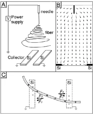
Aligned electrospun nanofibers can be obtained by manipulating the electrostatic forces that act on the charged jet. Thus replacing the plane collector by a specially designed one has an effect on the electric field at the vicinity of the collector.
The use of a rectangular collector [50, 51] (Figure 10-a) or of a collector consisting of two pieces of electrically conducting substrates separated by a gap [52, 53] (Figure 10-b) or an insulating substrate [54] results in the alignment of the electrospun nanofibers.
a) b)
Figure 10: a) Alignment of electrospun nanofibers over a rectangular frame electrode of 2 x 6 cm, reproduced from ref. [50] b) Nanofibers aligned between two conducting silicon stripes, Reprinted
with permission from [52].
2.1.1.1 Mechanism of alignment
The charged electrospun jet is subject to two kinds of electrostatic forces: forces induced by the external electric field and coulombic interactions between the landing jet and the collector or the already deposited nanofibers. Thus the landing fiber will first follow the direction of the electric field lines towards the two electrodes and will land across the gap (Figure 11). Then the induced image charges created at the surface of the grounded electrode by the highly charged fiber will generate coulombic attractive forces between the fiber and the oppositely charged
![Figure 7: Variation of fibers average diameter with []*C (■): zone 1: electrospraying, zone 2:](https://thumb-eu.123doks.com/thumbv2/123doknet/14544776.725287/43.918.270.654.573.874/figure-variation-fibers-average-diameter-zone-electrospraying-zone.webp)
![Figure 8: Deposition distance morphology of SLPF fibers a) with a distance = 2 cm; b) with a distance =0.5 cm ([47])](https://thumb-eu.123doks.com/thumbv2/123doknet/14544776.725287/46.918.237.682.109.372/figure-deposition-distance-morphology-slpf-fibers-distance-distance.webp)