HAL Id: tel-03104312
https://tel.archives-ouvertes.fr/tel-03104312
Submitted on 8 Jan 2021HAL is a multi-disciplinary open access archive for the deposit and dissemination of sci-entific research documents, whether they are pub-lished or not. The documents may come from teaching and research institutions in France or abroad, or from public or private research centers.
L’archive ouverte pluridisciplinaire HAL, est destinée au dépôt et à la diffusion de documents scientifiques de niveau recherche, publiés ou non, émanant des établissements d’enseignement et de recherche français ou étrangers, des laboratoires publics ou privés.
Lung deformation estimation using a hybrid
image-based/biomechanics-based approach for the
localization of pulmonary nodules during video- assisted
thoracoscopic surgery
Pablo Alvarez
To cite this version:
Pablo Alvarez. Lung deformation estimation using a hybrid image-based/biomechanics-based ap-proach for the localization of pulmonary nodules during video- assisted thoracoscopic surgery. Signal and Image processing. Université de Rennes 1, 2020. English. �tel-03104312�
T
HÈSE DE DOCTORAT DE
L’UNIVERSITÉ DE RENNES 1 COMUEUNIVERSITÉBRETAGNELOIRE ÉCOLE DOCTORALE N° 601
Mathématiques et Sciences et Technologies de l’Information et de la Communication Spécialité : Signal, Image, Vision
Par
Pablo A. ALVAREZ
Lung deformation estimation using a hybrid
image-based/biomechanics-based approach for the localization of pulmonary nodules during
video-assisted thoracoscopic surgery
Thèse présentée et soutenue à Rennes, le 9 novembre 2020
Unité de recherche : Laboratoire Traitement du Signal et de l’Image (LTSI), UMR Inserm 1099
Rapporteurs avant soutenance :
María J. Ledesma Carbayo Professeure, Université Polytechnique de Madrid
Stéphane Cotin Directeur de Recherche, INRIA, équipe MIMESIS, Strasbourg
Composition du Jury :
Présidente : Su Ruan Professeure, Université de Rouen
Examinateurs : María J. Ledesma Carbayo Professeure, Université Polytechnique de Madrid
Stéphane Cotin Directeur de Recherche, INRIA, équipe MIMESIS, Strasbourg
Su Ruan Professeure, Université de Rouen
Matthieu Chabanas Maître de Conférences, Université Grenoble-Alpes Dir. de thèse : Jean-Louis Dillenseger Maître de Conférences (HdR), Université de Rennes 1 Co-dir. de thèse : Yohan Payan Directeur de Recherche, CNRS, Université Grenoble-Alpes
Résumé
Le cancer du poumon est la première cause de décès par cancer dans le monde, tant chez les femmes que chez les hommes. Chaque année, il représente plus de 18% de tous les décès dus au cancer et fait presque autant de victimes que les cancers de la prostate, du foie et du sein réunis. Cette mortalité élevée est principalement due à une détection tardive de la maladie, lorsque les traitements curatifs ne sont plus disponibles et que la survie des patients est très faible. Heureusement, la récente mise en œuvre des programmes de dépistage a augmenté les chances de détection précoce du cancer du poumon, de traitement curatif en temps utile et, en fin de compte, de survie des patients.
Néanmoins, sur l’ensemble des nodules pulmonaires détectés par les programmes de dépistage, seule une fraction est un cancer du poumon. Il est important d’établir un diagnostic précis de ces nodules, car cela permet de déterminer un plan de trai-tement approprié pour le patient. Bien que divers tests médicaux puissent aider à prédire une malignité, seule l’analyse histologique d’échantillons de nodules peut confirmer la présence d’un cancer et de son sous-type. Cependant, ces nodules sont généralement trop petits, trop profonds ou pas assez denses pour que les techniques de biopsie non chirurgicales (e.g. biopsie transthoracique par aiguille du ponction ou biopsie bronchoscopique) soient fiables. Par conséquent, dans de nombreux cas, une biopsie chirurgicale (i.e. retrait complet du nodule) mini-invasive par thoraco-scopique vidéo-assistée (VATS), est la méthode préférée. En outre, cette résection chirurgicale des nodules pulmonaires est également la principale option de traite-ment à visée curative pour les patients atteints d’un cancer du poumon à un stade précoce. Bien que la lobectomie (i.e. la résection d’un lobe pulmonaire entier) par tho-racotomie ouverte soit la procédure classique, la pratique clinique a évolué vers des techniques de résection moins invasives qui préservent mieux le tissu pulmonaire. En fait, il a été démontré que les petites résections non anatomiques (i.e. résections cu-néiformes, wedge resections en anglais) par VATS pouvaient être réalisées sans aucun compromis sur le résultat clinique. En tant que tel, la VATS s’avère être un outil im-portant pour la gestion précoce du cancer du poumon, tant au niveau du diagnostic que du traitement.
Cependant, pendant la VATS, les nodules pulmonaires sont difficiles à localiser, car ils ne sont souvent ni palpables, ni visibles à l’œil nu. Cette situation est aggravée par la très grande déformation subie par le poumon à cause d’un pneumothorax. En effet, lorsque le chirurgien insère l’espace intercostal pour y placer les trocarts nécessaires au placement de la caméra et des outils, il se crée des entrés d’air qui entraînent le
dégonflement du poumon. Si ce pneumothorax donne l’espace nécessaire pour les manœuvres chirurgicales, il induit une profonde déformation du poumon et un fort déplacement du nodule. Pour surmonter ce problème, différentes stratégies de locali-sation des nodules pulmonaires sont couramment utilisées dans la pratique clinique. La principale consiste à placer des marqueurs physiques (e.g. hameçons, teintures) dans le nodule pour faciliter sa localisation pendant la chirurgie. Cette procédure est réalisée sous guidage scanner X, scanner cone beam CT (CBCT) ou bronchoscopique, soit de façon préopératoire (intervention suivie du transfert du patient au bloc opé-ratoire), soit de façon peropératoire (dans une salle d’opération hybride). Toutefois, cette procédure de marquage présente encore certaines limites, comme la possibilité de migration des marqueurs après le placement, la difficulté de placement à certains endroits anatomiques et diverses complications cliniques, notamment le pneumo-thorax, l’hémothorax et l’embolie. En outre, les procédures de placement de mar-queurs préopératoires comportent des risques et un inconfort supplémentaires pour le patient en attendant son transfert en salle d’opération, sans mentionner la charge logistique liée à la coordination des procédures de localisation et de résection. Le développement de techniques de localisation des nodules pulmonaires pour la VATS est toujours un domaine de recherche actif, avec des investigations en cours pour trouver des méthodes plus sûres, plus efficaces et plus fiables. Compte tenu des limites des stratégies de localisation actuelles, une procédure peropératoire ne nécessitant pas de marqueurs physiques externes est souhaitable. Dans ce contexte, une solution innovante pour la localisation peropératoire des nodules pulmonaires a été proposée par Rouzé et al. au CHU de Rennes. La méthode est basée sur la déli-mitation du nodule pulmonaire sur une image CBCT du poumon semi-dégonflé, ac-quise après un pneumothorax. Cette délimitation est ensuite projetée sur des images fluoroscopiques en tant que marqueur virtuel qui est utilisé pour guider la localisa-tion du nodule pulmonaire. Une étude clinique réalisée sur 24 patients a démontré la faisabilité de cette approche. Cependant, bien que prometteuse, cette technique de localisation de nodule sans marqueur repose entièrement sur la visibilité du nodule pulmonaire dans l’image de CBCT, mais celle-ci peut être insuffisante dans de nom-breux cas. En effet, le dégonflement du poumon dû au pneumothorax augmente la densité du parenchyme pulmonaire, ce qui diminue fortement le contraste d’inten-sité entre le nodule pulmonaire et le tissu environnant sur l’image CBCT, empêchant ainsi sa localisation.
Les nodules pulmonaires sont toujours visibles sur l’image scanner X préopératoire utilisées pour la planification du geste opératoire. L’idée principale de cette de Thèse est de fusionner, à l’aide de méthodes de recalage d’images, l’image scanner X pré-opératoire avec l’image CBCT perpré-opératoire afin de compenser la déformation des poumons et ainsi d’estimer la position peropératoire des nodules pulmonaires. Ce recalage permettra non seulement de localiser les nodules qui ne sont pas
directe-ment visibles sur l’image CBCT, mais égaledirecte-ment, à termes, d’ouvrir la porte à des techniques de guidage chirurgical plus avancées (par exemple la réalité augmentée) qui pourraient être utiles à la pratique clinique actuelle.
Objectif de la thèse
L’objectif principal de cette thèse est de proposer une méthode de recalage d’image qui tient compte de la déformation du poumon pendant la VATS, afin de fournir une estimation de la position peropératoire des nodules pulmonaires. Cette méthode de-vra être intégré dans la stratégie de localisation des nodules pulmonaires développée au CHU de Rennes, en tant que mécanisme potentiel permettant d’atténuer les diffi-cultés auxquelles cette méthode est actuellement confrontée.
Méthode de recalage pour la localisation peropératoire des
no-dules pulmonaires pendant la VATS
La déformation du poumon pendant la VATS peut être comprise comme le résultat de deux processus physiques de natures différentes. Le premier processus correspond au placement du patient sur la table d’opération. Lors de l’acquisition de l’image scanner X préopératoire, le patient est en décubitus dorsal, alors que sur la table d’opération le patient est en décubitus latéral. Ce changement de position entraîne une déformation de la cage thoracique et surtout un changement de l’orientation du corps par rapport à la gravité, ce qui provoque un déplacement et une déformation du poumon et des organes environnants sous l’effet de leur poids. Il est également à noter un relâchement du diaphragme dû à l’anesthésie avec pour conséquence un certain déplacement provoqué par le poids des organes abdominaux. Le second pro-cessus correspond au pneumothorax avec l’effondrement du poumon dans la cage thoracique. Cette thèse présente une première tentative de prise en compte de ces deux processus physiques, afin que la position du nodule pulmonaire puisse être projetée du cadre préopératoire au cadre chirurgical peropératoire. Cela a été réalisé en introduisant une image CBCT supplémentaire peropératoire du poumon avant le pneumothorax, ce qui a permis de décomposer le problème de recalage initial com-plexe en deux sous-problèmes plus faciles à traiter : le premier tenant compte de la déformation du changement de la pose du patient entre le scanner X préopératoire et son placement sur la table d’opération, et le second tenant compte de la déformation du pneumothorax. La méthodologie globale de la méthode de recalage proposée est présentée dans la figure 1.
Figure 1 :Aperçu de la méthode de recalage proposée pour la localisation des
no-dules pulmonaires pendant la VATS. La méthode est composée de deux étapes : la première pour estimer la déformation du poumon due au chan-gement de pose, et la deuxième pour estimer la déformation du poumon due au pneumothorax.
Estimation de la déformation du poumon due au changement de pose
L’objectif de cette première étape est d’estimer la configuration déformée du poumon complet après le changement de pose. Cette estimation fourni la géométrie peropé-ratoire du poumon gonflé, qui est nécessaire pour l’estimation de la déformation du pneumothorax dans la deuxième partie. Il est important de souligner que les images peropératoires CBCT ne présentent qu’une vue partielle du poumon. Par conséquent, une méthode de recalage seulement basée sur les intensités des images ne serait pas suffisante, car seule une géométrie partielle du poumon pourrait être estimée. Par conséquent, une méthode hybride a été utilisée à la place, avec un recalage par in-tensité d’image pour estimer partiellement la déformation du poumon, et un modèle biomécanique poroélastique pour extrapoler cette déformation pour l’ensemble du poumon.
Estimation de la déformation du poumon due au pneumothorax
L’objectif de cette deuxième étape est d’estimer la configuration déformée du pou-mon après pneumothorax. La déformation du pneumothorax est modélisée à l’aide d’un modèle biomécanique poroélastique linéaire qui permet de prendre compte de l’évacuation de l’air lorsque le poumon se dégonfle. La géométrie du poumon gonflé résultant de l’estimation du changement de pose est utilisée comme configuration initiale pour la simulation du pneumothorax. Pour la phase fluide du modèle poroé-lastique (air), des conditions aux limites inspirées du processus d’expiration ont été définies, car elles correspondent naturellement à un processus du dégonflement de poumon. Pour la phase solide de ce modèle (parenchyme), des conditions de contact avec la cavité thoracique et le diaphragme sont utilisées, et des conditions limites de déplacement sont appliquées sur la face médiane pour tenir compte de la déforma-tion du médiastin. Enfin, une formuladéforma-tion de problème inverse a été utilisée pour l’estimation des paramètres tissulaires, minimisant une fonction de coût basée sur une distance de surface à surface entre le modèle déformable et la surface pulmo-naire dégonflée observée dans l’image CBCT peropératoire.
Contexte et financement
Cette thèse est le résultat d’une forte collaboration entre deux équipes de recherche, partenaires du projet national français «Laboratoire d’Excellence CAMI». D’une part, l’équipe IMPACT du laboratoire LTSI de l’Université de Rennes 1, avec une expé-rience dans les techniques de traitement d’images appliquées à l’assistance chirur-gicale. D’autre part, l’équipe GMCAO du laboratoire TIMC-IMAG, Université de Grenoble-Alpes, avec une expérience dans les procédures médico-chirurgicales as-sistées par ordinateur. En outre, cinq mois (février 2018 - juin 2018) ont été passés au laboratoire Biomechanical modeling laboratory du Vanderbilt Institute for Surgery and
En-gineering (VISE), Université de Vanderbilt, Nashville, Tennessee, dans le cadre d’un
programme de mobilité internationale.
De plus, cette thèse a été développée en parallèle avec la thèse de Sciences de Simon Rouzé (M.D.), chirurgien cardio-thoracique au CHU de Rennes, France, qui a initié le projet de recherche clinique sur la localisation peropératoire sans marqueurs guidée par la CBCT pour la VATS.
Le financement de cette thèse a été partagé par la Région Bretagne à travers des «Allo-cations de Recherche Doctorale» (ARED) et l’Agence Nationale de Recherche (ANR) à travers le cadre «Investissements d’Avenir Labex CAMI» (ANR-11-LABX-0004).
Structure du document
Ce manuscrit de thèse est divisé en sept chapitres et un annexe.
Le Chapitre 4, le Chapitre 5, le Chapitre 6 et l’Annexe A ont tous été basés sur des publications présentées en conférences ou soumises à une revue internationale. Ces chapitres sont divisés en deux parties. La première partie reproduit le contenu de la publication sans modification. La seconde partie présente des méthodes et des résul-tats supplémentaires qui complètent le travail rapporté dans la publication. Afin de différencier clairement les deux parties, toutes les pages appartenant à une publica-tion sont marquées par une bande verticale, comme celle qui se trouve à côté de ce paragraphe.
Le Chapitre 1 fournit une description du contexte clinique dans lequel s’inscrit ce travail de thèse. Ce chapitre commence par donner un aperçu de l’anatomie et de la fonction pulmonaire. Ensuite, une vue d’ensemble sur le cancer du poumon et de sa gestion est présentée, en se focalisant plus sur la résection chirurgicale des nodules pulmonaires par VATS. Ensuite, les principales stratégies de localisation des nodules pulmonaires par VATS sont énumérées, la méthode de localisation peropératoire pro-posée au CHU de Rennes étant une solution alternative. Les principaux avantages et limites actuelles de ces méthodes de localisation sont discutés, ce qui conduit à la motivation principale de cette thèse.
Le Chapitre 2 présente le contexte méthodologique des travaux développés dans cette thèse. Deux stratégies de compensation et d’analyse des déformations y sont brièvement décrites : celle du recalage d’images basé sur l’intensité et celle de la mo-délisation biomécanique. Ensuite, une revue de la littérature sur les méthodes de compensation des déformations pulmonaires est proposée, les méthodes étant clas-sées en fonction de la stratégie utilisée.
Le Chapitre 3 donne un aperçu global de la méthode de recalage proposée pour la localisation des nodules pulmonaires pendant la VATS et développée durant le travail de la Thèse, ainsi que des justifications des principaux choix méthodologiques. Pour ce faire, ce chapitre décrit tout d’abord les défis techniques à relever ainsi que les solutions proposées/possibles. Ensuite, le déroulement général de la méthode de recalage est présenté, ainsi que les données cliniques acquises pour sa validation, et la liste des principales investigations menées dans le cadre de cette thèse.
Le Chapter 4 présente une caractérisation de la déformation pulmonaire résultant d’un changement de pose du patient entre les configurations préopératoires et per-opératoires du patient pendant la VATS. Cette déformation a d’abord été estimée à l’aide d’une méthode de recalage basée sur l’intensité, puis a été quantifiée et carac-térisée à l’aide d’indices de déformation issus de la littérature. Les résultats prélimi-naires de cette étude ont été présentés lors d’une conférence internationale :
P. Alvarez, M. Chabanas, S. Rouzé, M. Castro, Y. Payan, and J.-L. Dillenseger. Lung deformation between preoperative CT and intraoperative CBCT for tho-racoscopic surgery : a case study. In Medical Imaging 2018 : Image-Guided
Proce-dures, Robotic Interventions, and Modeling, page 40, Houston, United States, Mar.
2018. SPIE. ISBN 978-1-5106-1641-7. doi : 10.1117/12.2293938
Le Chapitre 5 présente une première mise en œuvre de la méthode de recalage propo-sée pour la localisation des nodules pulmonaires. Pour faciliter cette mise en œuvre, les données cliniques ont été obtenues dans le contexte d’une biopsie par aiguille de ponction du poumon au lieu d’une intervention de VATS. Cela a permis de traiter des déformations pulmonaires très similaires à celles du VATS, tout en utilisant des données cliniques moins difficiles. Les résultats de cette étude ont été présentés lors d’une conférence internationale :
P. Alvarez, S. Narasimhan, S. Rouzé, J.-L. Dillenseger, Y. Payan, M. I. Miga, and M. Chabanas. Biphasic model of lung deformations for video-assisted thoraco-scopic surgery (VATS). In 2019 IEEE 16th International Symposium on Biomedical
Imaging (ISBI 2019), pages 1367–1371, Venice, Italy, 2019a. IEEE. ISBN
978-1-5386-3641-1. doi : 10.1109/isbi.2019.8759219
Le Chapitre 6 présente la mise en œuvre finale de la méthode de recalage proposée pour la localisation des nodules pulmonaires pendant la VATS. Cette mise en œuvre s’appuie sur les travaux présentés dans les deux chapitres précédents afin d’étendre la méthode développée du contexte de la biopsie par aiguille de ponction du poumon au contexte de la VATS. Ce dernier est plus difficile en raison de la qualité des données cliniques et de la quantité de déformations pulmonaires. Les résultats de cette étude ont été soumis à une revue internationale et sont actuellement en cours de révision : P. Alvarez, S. Rouzé, M. I. Miga, Y. Payan, J.-L. Dillenseger, and M. Chabanas. A hybrid image registration approach to markerless intraoperative nodule lo-calization during video-assisted thoracoscopic surgery. Medical Image Analysis, submitted in April 2020
Le Chapitre 7 fait le compte des principales contributions de ce travail de thèse et discute des lignes de recherche envisageables pour des développements futurs. L’Annexe A évalue la méthode de recalage basé sur l’intensité introduit au chapitre 4 comme outil de localisation des nodules pulmonaires pendant la VATS. Cette étude permet d’illustrer la difficulté de la tâche à accomplir, et comment un algorithme classique basé seulement en des intensités d’image peut ne pas être suffisant pour construire une solution. Les résultats de cette étude ont été présentés lors d’une conférence internationale :
P. Alvarez, S. Rouzé, M. Chabanas, Y. Payan, and J.-L. Dillenseger. Image-based registration for lung nodule localization during VATS. In Surgetica 2019, Rennes, France, 2019
To my beloved parents and sister for their unconditional love that travels all distances
Acknowledgements
First of all, I would like to thank María J. Ledesma, associate professor at the
Univer-sidad Politécnica de Madrid and Stéphane Cotin, research director at INRIA and head
of the MIMESIS team, for accepting to review this manuscript. I am also grateful to them and to Su Ruan, professor at the Université de Rouen, for participating in the jury of my thesis and for their interest in my work, which lead to very exciting discussions and interesting ideas.
I would like to express my sincere gratitude to my supervisors Jean-Louis Dillenseger, associate professor at the Université de Rennes 1, Yohan Payan, CNRS research director at the Université Grenoble-Alpes, and Matthieu Chabanas, associate professor at the
Université Grenoble-Alpes. Their complementary expertise was fundamental for the
accomplishment of this thesis, and they masterfully made it accessible to me in form of useful advice. I greatly thank them also for their kindness and encouragement throughout these four years.
I am deeply grateful to Simon Rouzé, cardiothoracic surgeon at the CHU
Pontchail-lou, without whom this research project would not have been born. Many thanks to
him also for his role as my medical conscience, and his investment in acquiring and annotating the clinical data that was key for the development of this thesis.
I extend my special thanks to the people at the Vanderbilt Institute for Surgery and Engineering, from Vanderbilt University, where I spent 5 months for a mobility pro-gram. I am particularly grateful to professor Michael I. Miga and colleges from the Biomedical Modeling Laboratory for sharing with me their knowledge and methods on the poroelastic biomechanical model, which was central to my research.
I also truly thank the laboratory that so warmly hosted me during these four years, the LTSI. Not only did my stay there widen my knowledge, but it gave me the chance to meet many incredible people, many of which I now consider friends.
Many thanks to all my friends for their gracious company, it was a constant source of support and joyful experiences. In particular, I would like to express my profound gratitude to my dear friends Lara, Karim, Sandie and Margaux, along whom I have experienced some of my most pleasurable years.
I am also very grateful to Marcela Iregui, Eduardo Romero and Oscar Acosta, who saw in me the potential for becoming a researcher, and consequently, pushed me down this way and guided my initial steps.
Table of Contents
Résumé iii
Acknowledgements xiii
Table of Contents xv
List of Figures xix
List of Tables xxv
Introduction 1
1 Clinical context 7
1.1 Lung anatomy and breathing . . . 7
1.1.1 Gross anatomy and function . . . 7
1.1.2 Mechanisms of breathing . . . 10
1.2 Lung cancer . . . 14
1.2.1 Early lung cancer detection . . . 15
1.2.2 Lung cancer diagnosis and staging . . . 17
1.2.3 Treatment strategies for NSCLC . . . 18
1.3 Video-Assisted Thoracoscopic Surgery (VATS) . . . 22
1.3.1 Surgical procedure . . . 23
1.3.2 Nodule localization for wedge resection . . . 26
1.3.3 Intraoperative CBCT for pulmonary nodule localization dur-ing VATS . . . 29
2 Lung motion compensation: background and related works 33 2.1 Intensity-based image registration . . . 33
2.1.1 Medical image . . . 33
2.1.2 Registration framework . . . 34
2.2 Biomechanical modeling . . . 38
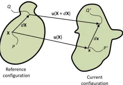
2.2.1 Description of motion . . . 38
2.2.2 Deformation and strain . . . 39
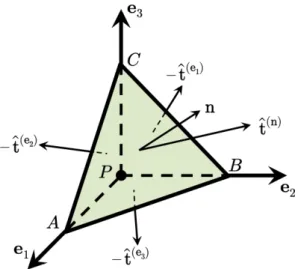
2.2.3 Stress . . . 42
2.2.4 Elasticity . . . 45
2.3 Related works in lung deformation compensation . . . 48
2.3.2 Biomechanical model-based methods . . . 50
2.3.3 Hybrid methods . . . 51
2.3.4 Summary . . . 53
3 Challenges, method overview and clinical data 55 3.1 Technical challenges and methodological choices . . . 55
3.1.1 Challenge of CBCT images . . . 55
3.1.2 Challenge of large lung deformation . . . 57
3.1.3 Challenge of modeling lung deformation . . . 58
3.1.4 Challenge of clinical compatibility . . . 59
3.2 A hybrid registration framework to markerless intraoperative pulmonary nodule localization during VATS . . . 59
3.2.1 Phase 1: estimation of change of pose deformation . . . 60
3.2.2 Phase 2: estimation of pneumothorax deformation . . . 61
3.3 Clinical data . . . 61
3.3.1 Clinical dataset . . . 61
3.3.2 Anatomical landmarks for validation . . . 63
3.4 Summary of the main investigations . . . 64
4 Characterization of lung deformation after a change of patient pose during VATS 67 Foreword . . . 67
Article: Lung deformation between preoperative CT and intraoperative CBCT for thoracoscopic surgery: a case study . . . 68
4.1 Introduction . . . 68
4.2 Materials and Methods . . . 69
4.2.1 Data . . . 69 4.2.2 Segmentation . . . 70 4.2.3 Registration . . . 71 4.3 Results . . . 72 4.4 Discussion . . . 74 4.5 Conclusion . . . 75
Additional methodological aspects, results and discussion . . . 77
General conclusion . . . 87
5 A hybrid registration framework for lung deformation compensation after change of pose and pneumothorax: an initial investigation 89 Foreword . . . 89
Article: Biphasic model of lung deformations for Video-Assisted Thoraco-scopic Surgery (VATS) . . . 91
5.2 Materials and Methods . . . 92
5.2.1 Data . . . 92
5.2.2 Finite element model . . . 92
5.2.3 Geometry reconstruction . . . 93
5.2.4 Material properties . . . 93
5.2.5 Initial alignment . . . 94
5.2.6 Deformation compensation strategy . . . 95
5.3 Experimental results . . . 97
5.4 Discussion and conclusion . . . 98
Additional results and discussion . . . 100
General conclusion . . . 104
6 A hybrid registration framework for lung deformation compensation during VATS 105 Foreword . . . 105
Article: A hybrid image registration approach to markerless intraoperative nodule localization during video-assisted thoracoscopic surgery . . . . 106
6.1 Introduction . . . 106
6.2 Related works . . . 109
6.2.1 Intensity-based image registration methods for lung deforma-tion compensadeforma-tion . . . 109
6.2.2 Biomechanical model-based methods for lung deformation com-pensation . . . 110
6.2.3 Hybrid methods for lung deformation compensation . . . 113
6.3 Method Overview . . . 114
6.4 Poroelastic model of the lung . . . 117
6.5 Preprocessing of the CBCT images . . . 120
6.6 Phase 1: Estimation of the change of pose deformation . . . 121
6.6.1 Image-based change of pose estimation . . . 121
6.6.2 Extrapolation of the deformation to the entire lung . . . 124
6.7 Phase 2: Estimation of the pneumothorax deformation . . . 125
6.7.1 Intraoperative data processing . . . 125
6.7.2 Simulation of the pneumothorax . . . 127
6.7.3 Inverse problem formulation . . . 130
6.7.4 Nodule localization . . . 131
6.8 Results . . . 131
6.8.1 Clinical dataset . . . 132
6.8.2 Results: Phase 1, estimation of the change of pose . . . 133
6.8.3 Results: Phase 2, estimation of the pneumothorax . . . 135
6.8.4 Variants of the method . . . 138
6.9.1 Hybrid approach to deformation estimation . . . 141
6.9.2 Modeling choices . . . 142
6.9.3 Inverse formulation approach . . . 143
6.9.4 Diaphragm movement . . . 143
6.9.5 Towards clinical practice: practicability and accuracy . . . 144
6.10 Conclusion . . . 144
Additional results and discussion . . . 146
General conclusion . . . 151
7 Summary, perspectives and conclusion 153 Appendices 159 A Image-based registration for lung nodule localization during VATS 161 Foreword . . . 161
Article: Image-based registration for lung nodule localization during VATS . 162 A.1 Introduction . . . 162
A.2 Materials and Methods . . . 163
A.2.1 Clinical data . . . 163
A.2.2 Segmentation . . . 163
A.2.3 Nodule localization approach . . . 163
A.3 Results and Discussion . . . 164
A.4 Conclusion . . . 165
Additional discussion . . . 166
General conclusion . . . 167
List of publications 169
List of Figures
1 Aperçu de la méthode de recalage proposée pour la localisation des
nodules pulmonaires pendant la VATS . . . vi
1.1 Coronal view of gross lung anatomy . . . 8
1.2 Pleural cavity and main lung structures . . . 9
1.3 Overview of air transport and gas exchange . . . 10
1.4 Principal respiratory pressures . . . 11
1.5 Inhalation and exhalation phases of breathing . . . 13
1.6 Illustration of pneumothorax . . . 14
1.7 Incidence and mortaility rates for the 5 main cancer types . . . 15
1.8 Comparison of surgical incisions in open thoracotomy and VATS . . . 22
1.9 A typical operating room setup for VATS. . . 24
1.10 Hybrid operating room at the Rennes University Hospital . . . 29
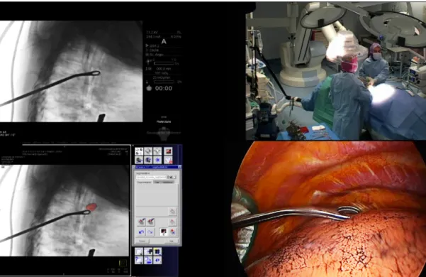
1.11 Manual delineation of a pulmonary nodule in an intraoperative CBCT image of a semi-deflated lung . . . 30
1.12 Intraoperative localization of a pulmonary nodule under fluoroscopic guidance . . . 31
1.13 Comparison of low-dense GGO nodule visibility in preoperative and intraoperative images . . . 31
2.1 Illustration of a medical image in two dimensions . . . 34
2.2 Spatial mapping in image registration . . . 35
2.3 Reference and current configurations of a body subject to deformation. 39 2.4 A body divided into two parts by a cross-sectional surface S . . . 43
2.5 Free-body diagram of a tetrahedron having its vertex at a point P . . . 44
3.1 Coronal and axial slices of a CBCT image of the deflated lung illustrat-ing some of the technical challenges . . . 56
3.2 Overview of the proposed registration framework for pulmonary nod-ule localization during VATS . . . 60
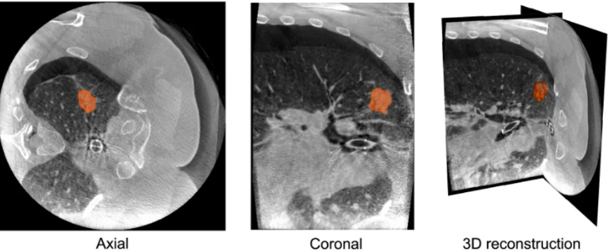
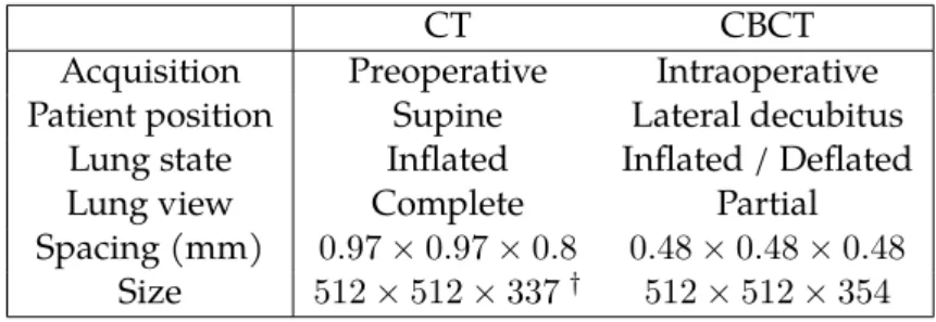
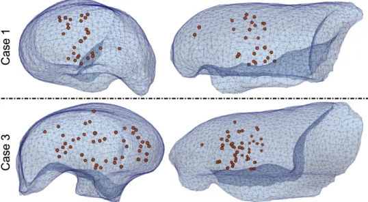
3.3 Coronal slices of structural tomographic images acquired for a VATS intervention. Left: preoperative CT image with the patient in supine position. Right: intraoperative CBCT images of the inflated (top) and deflated (bottom) lung with the patient in lateral decubitus position. Middle: superposition of the preoperative CT image rigidly registered to the intraoperative CBCT image of the deflated lung. The FOV of the CBCT image (outlined in yellow) only provides a partial view of the lung. The pulmonary nodule is encircled in the preoperative CT image and is visible in all other images. . . 62 3.4 Spatial distribution of anatomical landmarks within the lung . . . 64 4.1 Slices in approximately the same transversal plane for preoperative
CT (supine position) and intraoperative CBCT (lateral decubitus po-sition). The nodule is encircled in orange. The change of configuration from preoperative to intraoperative configurations is clearly visible. . . 70 4.2 Axial view of the lung. Left: CT-CBCT image overlap after rigid
regis-tration. Middle: CT-CBCT image overlap after non-rigid regisregis-tration. Right: target intraoperative CBCT image. . . 72 4.3 Target Registration Errors (TRE) in millimeters for different landmark
groups before and after non-rigid registration. . . 73 4.4 Spatial distribution of the whole set of landmarks. Left: Color map
rep-resentation of the TREs after non-rigid registration, for all landmarks. Middle: Set of preoperative periphery landmarks (red spheres) af-ter rigid registration compared to intraoperative periphery landmarks (blue squares). Right: Set of preoperative periphery landmarks (green spheres) after non-rigid registration compared to intraoperative pe-riphery landmarks (blue squares). . . 73 4.5 Left: color mapped local deformations in millimeters for coronal and
axial views of the lung. Right: the normalized histogram of local de-formations in millimeters for the whole lung volume. . . 74 4.6 Result of change of pose rigid registration using the spine as the reference 78 4.7 Lung segmentation in CBCT image of the inflated lung . . . 79 4.8 TRE distributions for change of pose rigid and elastic registration . . . 81 4.9 Sagittal and coronal slices of estimated deformation measurements for
Case 4 . . . 83 4.10 Sagittal and coronal slices of estimated deformation measurements for
Case 6 . . . 84 4.11 Distributions of estimated displacement magnitude for all clinical cases 85 4.12 Distributions of estimated J for all clinical cases . . . 85 4.13 Distributions of estimated ADI for all clinical cases . . . 86
5.1 Left lung containing a solid, solitary nodule, indicated with a circle. Left: Axial cut of the CT image with the patient in supine position. Right: Axial cut of the LDCT image after pneumothorax with the pa-tient in lateral decubitus position. The pneumothorax is indicated by arrows. . . 93 5.2 Left: Tetrahedral mesh of lung parenchyma from the CT image (Lct).
Middle: Tetrahedral mesh of the thoracic cage from the LDCT image (Lldct). Right: Example of mesh stratification on Lldct and the
corre-sponding values of Young’s modulus E (Emin=0.1 kPa and Emax=1 kPa). 94 5.3 TREs after three levels of deformation compensation. . . 97 5.4 Left: Spatial distribution of post-deformation landmarks represented
with a color code indicating TREs. Right: 3D reconstructions of the ground truth tumor (in blue), deformation compensated tumor (in green) and rigidly transformed tumor (in black). The surfaces repre-sent Lldctbefore and after simulation of pneumothorax. . . 98 5.5 Depth of airways and continuous stiffness approximation . . . 101 5.6 Comparison of deformation compensation results with homogeneous
and heterogeneous Young’s Modulus . . . 101 6.1 Left: preoperative CT image with the patient in supine position. Right:
intraoperative CBCT images of the inflated (CBCTinf) and deflated (CBCTdef) lung with the patient in lateral decubitus position. Middle: superposition of the preoperative CT image rigidly registered to the intraoperative CBCTdef image. The FOV of the CBCTdef image (out-lined in yellow) only provides a partial view of the lung. The nodule is encircled in the preoperative CT image and is in this visible in all other images. . . 115 6.2 Overview of the proposed nodule localization framework. The process
is split into two stages, Phase 1 and Phase 2, that respectively estimate the change of pose deformation then the pneumothorax deformation. . 116 6.3 Schematic diagram of the Phase 1 process to estimate the change of
pose deformation. The top block illustrates the image-based registra-tion of the preoperative CT and intraoperative CBCTinf images. After rigidly registering the spine, an elastic registration based on anatom-ical segmentations of the lung is carried out. The bottom block con-cerns the estimation of the complete lung geometry after the change of pose deformation. The previously computed deformation field is transferred as imposed displacements boundary conditions on a FEM model. This model extrapolates the deformation to the whole extent of the lung, including regions that are not within the FOV of the CBCTinf image. . . 122
6.4 Schematic diagram of the Phase 2 stage to estimate the pneumotho-rax deformation. Intraoperative images are processed to segment the surface of the deflated lung, and to compute a deformation field ap-proximating the hilum deformation between CBCTinf and CBCTdef. An inverse problem based on FE simulations estimated the pneumoth-orax deformation. Tissue parameters were optimized until the simu-lated model best fits the intraoperative data. Finally, the intraoperative nodule position is obtained by warping the undeformed position with the simulated pneumothorax deformation. . . 126 6.5 Schematic representation of the pneumothorax phenomenon. Left, the
state of the lung at end of expiration. The lung is at equilibrium and no airflow is present. Right, the rupture in the parietal pleura makes the intrapleural negative pressure vanish which voids the outward recoil from the chest wall. The transmural pressure and the inward recoil of the alveoli produce the lung deflation observed during a pneumothorax.128 6.6 Spatial distribution of anatomical landmarks within the lung FE mesh
reconstructed from the preoperative CT image. . . 133 6.7 TRE distributions for rigid and elastic registration between the
preop-erative CT and intraoppreop-erative CBCTinf (Phase 1, change of pose). . . . 134 6.8 Qualitative results of rigid and elastic registration between the
pre-operative CT (green) and intrapre-operative CBCTinf (magenta) images. Coronal slices are shown for two representative cases. The target CBCTinf image in gray-scale is shown in the far right column. . . 135 6.9 TRE distributions for our complete deformation compensation
frame-work, alongside the errors expected without deformation compensa-tion. These latter distributions correspond to rigidly registering the preoperative CT with the CBCTinf and CBCTdef images, respectively. . 136 6.10 Qualitative results of our deformation compensation framework for
two clinical cases. Left: final deformed lung FE mesh superposed over the extracted deflated lung surface (in green). Middle: Registered land-mark errors, deformed FE lung mesh and thoracic cage contact surface. Right: Initial nodule position (wireframe, black surface), ground truth nodule position (wireframe, green surface) and predicted nodule po-sition (solid, purple surface). . . 137 6.11 Qualitative results of our deformation compensation framework for
two representative cases. The CT and CBCTinf images are rigidly reg-istered to the CBCTdefimage. Coronal slices of exactly the same region of interest are shown for all images. The color contours illustrate the position of the FE mesh at the beginning of Phase 1 (cyan) and Phase 2 (orange), as well as at the end of Phase 2 (purple). . . 139
6.12 TRE distributions for three variants of the proposed lung deformation compensation method. . . 140 6.13 TRE distributions for our deformation compensation framework with
and without including the upward diaphragm movement. . . 141 6.14 Qualitative result of the proposed deformation compensation method
in Case 1. . . 146 6.15 Qualitative result of the proposed deformation compensation method
in Case 2. . . 148 6.16 Qualitative result of the proposed deformation compensation method
in Case 3. . . 148 6.17 Qualitative result of the proposed deformation compensation method
in Case 4. . . 149 6.18 Qualitative result of the proposed deformation compensation method
in Case 5. . . 149 6.19 TRE distributions of intensity-based registration and hybrid
registra-tion frameworks for Case 1 . . . 150 A.1 Left: the preoperative CT with the segmentation of the lung (cyan)
and its extension (green). Right: the intraoperative CBCT with the segmentations of the lung (cyan) and the thoracic cage (orange). The pneumothorax is the space between the lung and the thoracic cavity. . 163 A.2 Result of nonrigid registration with NCC. The preoperative CT is shown
to the left. The deformed CT and the CBCT are shown to the right. Col-ored circles indicate the paired landmarks for the tumor. The image in the window is a closeup of the superposition of the result. . . 165
List of Tables
1.1 The TNM system for cancer staging . . . 18 1.2 Overview of lung cancer staging . . . 19 3.1 Details for image acquisitions within the in-house VATS clinical
work-flow . . . 62 3.2 Study characteristics for the 6 clinical cases considered . . . 63 6.1 Material properties and their values during pneumothorax
simula-tions. The last three parameters are patient and intervention specific and varied within the reported range during an optimization process. 130 6.2 Study characteristics for each clinical case. The pneumothorax was
con-trolled following two techniques: mechanical control of air inflow into the lung through the intubation tube; or pressurized insufflation of CO2into the thoracic cage through airtight trocars. The number of
val-idation landmarks depends on the visibility of lung structures in the images. . . 132 6.3 Tissue parameters estimated from our inverse problem optimization
approach: intrabronchi permeability (κb), tissue porosity (φ), and di-aphragm upward displacement (ddiaph). . . 138 6.4 Observations on qualitative results of the proposed deformation
Introduction
Lung cancer is the worldwide leading cause of cancer death among both women and men. Every year, it accounts for more than 18% of all cancer deaths, claiming almost as many lives as do prostate, liver and breast cancer combined. This high mortal-ity is primarily caused by a late detection of the disease, when curative treatment is no longer available and patient survival is very low. Fortunately, the recent develop-ment of screening programs has increased the chances for early lung cancer detection, timely curative treatment, and ultimately, patient survival.
Nonetheless, of all pulmonary nodules detected through screening programs, only a fraction are lung cancer. It is important to establish an accurate diagnosis of these nodules, as it allows to determine an appropriate treatment plan for the patient. Al-though various medical tests may help in predicting for malignancy, only histologi-cal analysis of nodule samples can confirm the presence of cancer and its sub-type. However, these nodules are typically too small, too deep, or not dense enough for non-surgical biopsy techniques (e.g. transthoracic needle biopsy or bronchoscopic biopsy) to be reliable. Consequently, in many cases, surgical biopsy (i.e. complete re-moval of the nodule) through the minimally invasive video-assisted thoracoscopic surgery (VATS) is the preferred method. In addition, this surgical resection of pul-monary nodules is also the main treatment option with curative intent for patients with early stage lung cancer. Although lobectomy (i.e. removal of an entire lung lobe) through open thoracotomy is the classical procedure, the clinical practice has been evolving towards less invasive, better tissue-preserving resection techniques. In fact, it has been demonstrated that small non-anatomical resections (i.e. wedge resections) through VATS could be performed without any compromise in the clinical outcome. As such, VATS reveals as an important tool for early lung cancer management in both, diagnosis and treatment.
During VATS, however, pulmonary nodules are difficult to localize, as they are of-ten neither palpable, nor visible to the naked eye. This is aggravated by the very large lung deformation resulting from pneumothorax (i.e. lung deflation caused by the entrance of air in the thoracic cavity), as the surgeon clears up space for surgical maneuvering. To overcome this problem, various nodule localization strategies are commonly used in clinical practice. The main approach consists in placing physical markers (e.g. hook-wires, micro-coils, dyes) in the nodule to facilitate its localization during surgery. This is carried out under CT, cone-beam CT (CBCT) or bronchoscopy guidance, either preoperatively (interventional procedure followed by patient trans-fer to the operating room) or intraoperatively (in a hybrid operating room). However,
there are still some limitations to this marking procedure, such as the possibility for marker migration after placement, the difficult placement at some anatomical loca-tions and various clinical complicaloca-tions including pneumothorax, hemothorax and embolism. Furthermore, preoperative marker placement procedures bear additional risks and discomfort for the patient while he/she awaits for transfer to the operating room, not to mention the logistic burden of coordinating the localization and resec-tion procedures.
The development of pulmonary nodule localization techniques for VATS is still an active area of research, with ongoing investigations towards safer, more efficient and more reliable methods. Considering the limitations of current localization strategies, an intraoperative procedure not requiring physical markers is desirable. In this con-text, an innovative solution for intraoperative pulmonary nodule localization has been proposed by Rouzé et al., at the Rennes University Hospital. The method is based on the delineation of the pulmonary nodule on a CBCT image of the semi-deflated lung, acquired after pneumothorax. This delineation is then projected into fluoroscopic images as a virtual marker serving for guidance. A clinical study per-formed on 24 patients demonstrated the feasibility of this approach. However, while promising, this markerless nodule localization technique relies entirely on the visibil-ity of the pulmonary nodule in the CBCT image, which may be insufficient in many cases. Indeed, the lung deflation after pneumothorax increases the density of lung parenchyma, which in turn decreases the intensity contrast between the pulmonary nodule and the surrounding tissue in the CBCT image.
An important observation is that pulmonary nodules are always visible in the CT im-age that is used for surgical planning. Hence, it should be possible to integrate this preoperative CT image and the intraoperative CBCT image into an image registration framework, in order to compensate for lung deformation and estimate the intraoper-ative position of pulmonary nodules. This would not only help with the localization of the nodules that are not directly observable in the CBCT image, but would also open the door for more advanced surgical guidance techniques that could benefit the current clinical practice.
Thesis objective
The main objective of this thesis is to propose a registration framework that accounts for lung deformation during VATS, in order to provide an estimation of the intra-operative position of pulmonary nodules. This registration framework has to be in-tegrated into the pulmonary nodule localization strategy developed at the Rennes University Hospital, as a potential mechanism to alleviate the challenges that this method currently faces.
Context and funding
This thesis is the result of a strong collaboration between two research teams, which are partners of the nation-wide french project “Laboratory of Excellence CAMI”. On the one hand, the IMPACT team from the LTSI laboratory, University of Rennes 1, with experience in image processing techniques applied to surgical assistance. On the other hand, the GMCAO team from the TIMC-IMAG laboratory, University Grenoble-Alpes, with experience in computer assisted medical-surgical procedures. In addition, 5-months (February 2018 - June 2018) were spent at the Biomechanical Modeling Laboratory of the Vanderbilt Institute for Surgery and Engineering (VISE), University of Vanderbilt, Nashville, Tennessee, within the context of an international mobility program.
Also, this thesis was developed in parallel to the Ph.D. thesis of Simon Rouzé (M.D.), cardio-thoracic surgeon at the Rennes University Hospital, Rennes, France, who ini-tiated the clinical research project on markerless CBCT-guided VATS.
The funding for this thesis was shared by the Région Bretagne through its Allocations
de Recherche Doctorale (ARED) framework and the Agence National de Recherche (ANR)
through the framework Investissements d’Avenir Labex CAMI (ANR-11-LABX-0004).
Thesis outline
This thesis manuscript is divided into seven chapters and one appendix.
Chapter 4, Chapter 5, Chapter 6 and Appendix A are all based from a manuscript. These chapters are each divided in two parts. The first part reproduces the content of the manuscript without modification. The second part presents additional methods and results that complement the work reported in the manuscript. In order to clearly differentiate the two parts, all pages belonging to a manuscript have been decorated with a vertical stripe, such as the one next to this paragraph.
Chapter 1 provides a description of the clinical context encompassing this thesis work. The chapter starts with an overview of lung anatomy and function. Then, an overall picture of lung cancer and lung cancer management is presented, with a spe-cial emphasis in surgical resection of pulmonary nodules through VATS. Following, the major strategies for pulmonary nodule localization for VATS are listed, with the intraoperative localization method proposed at the Rennes University Hospital as an alternative solution. The main advantages and current limitations of these methods are discussed, which lead to the main motivation of this thesis.
Chapter 2introduces the methodological background of the work developed in this thesis. Therein, two strategies for deformation compensation and analysis are briefly
described: that of intensity-based image registration and that of biomechanical mod-eling. Then, a review of the literature for lung deformation compensation methods is proposed, with the methods being classified with respect to the strategy used. Chapter 3 provides an overview of the proposed registration framework for pul-monary nodule localization during VATS, as well as justifications for the main method-ological choices. This is done by first introducing the technical challenges that needed to be addressed, and the proposed/potential solutions. Then, the overall workflow of the registration framework is presented, as well as the clinical data collected for its validation, and the list of the main investigations carried out in this thesis.
Chapter 4presents a characterization of the lung deformation resulting from a change of patient pose between the preoperative and the intraoperative settings in a VATS intervention. This deformation was first estimated using an intensity-based image registration framework, and was subsequently quantified and characterized using deformation indexes issued from the literature. The preliminary results of this study were presented in an international conference:
P. Alvarez, M. Chabanas, S. Rouzé, M. Castro, Y. Payan, and J.-L. Dillenseger. Lung deformation between preoperative CT and intraoperative CBCT for tho-racoscopic surgery: a case study. In Medical Imaging 2018: Image-Guided
Proce-dures, Robotic Interventions, and Modeling, page 40, Houston, United States, Mar.
2018. SPIE. ISBN 978-1-5106-1641-7. doi: 10.1117/12.2293938
Chapter 5presents a first implementation of the proposed registration framework for pulmonary nodule localization. To facilitate this implementation, the clinical data was obtained from the context of a lung needle-biopsy instead of a VATS interven-tion. This allowed dealing with lung deformation very similar to that of VATS, but with less challenging clinical data. The results of this study were presented in an international conference:
P. Alvarez, S. Narasimhan, S. Rouzé, J.-L. Dillenseger, Y. Payan, M. I. Miga, and M. Chabanas. Biphasic model of lung deformations for video-assisted thoraco-scopic surgery (VATS). In 2019 IEEE 16th International Symposium on Biomedical
Imaging (ISBI 2019), pages 1367–1371, Venice, Italy, 2019a. IEEE. ISBN
978-1-5386-3641-1. doi: 10.1109/isbi.2019.8759219
Chapter 6presents the final implementation of the proposed registration framework for pulmonary nodule localization during VATS. This implementation builds upon the work presented in the previous two chapters in order to extend the developed framework from the context of lung needle-biopsy to the context of VATS. This latter is more challenging because of the quality of clinical data, and the amount of lung deformation. The results of this study were submitted to an international journal, and are currently under review:
P. Alvarez, S. Rouzé, M. I. Miga, Y. Payan, J.-L. Dillenseger, and M. Chabanas. A hybrid image registration approach to markerless intraoperative nodule lo-calization during video-assisted thoracoscopic surgery. Medical Image Analysis, submitted in April 2020
Chapter 7reviews the main contributions of this thesis work and discusses possible lines of research for future developments.
Appendix Aevaluates the intensity-based image registration framework introduced in Chapter 4 as a tool for pulmonary nodule localization during VATS. This study allows to illustrate the difficulty of the task at hand, and how a classical algorithm based on image intensity alone may not be sufficient for constructing a solution. The results of this study were presented in an international conference:
P. Alvarez, S. Rouzé, M. Chabanas, Y. Payan, and J.-L. Dillenseger. Image-based registration for lung nodule localization during VATS. In Surgetica 2019, Rennes, France, 2019
Clinical context
1
The objective of this chapter is to introduce the clinical problem that is addressed in this manuscript. First of all, the main notions of lung anatomy and function are provided, with emphasis in the physical mechanisms that allow human respiration. Then, an overview of lung cancer statistics and lung cancer management is given. Particular interest is accorded to the early detection of the disease, as well as the pos-sible treatment options at this stage, which have been proven beneficial for patient survival. Finally, the video-assisted thoracoscopic surgery (VATS) is introduced as one of the main treatment options for early stage lung cancer. The advantages of this minimally invasive technique are discussed, as well as its main limitation: the need for pulmonary nodule localization. An overview of existing localization techniques is presented, with a focus on current trends in clinical practice. This chapter finishes by describing an alternative pulmonary nodule localization technique recently intro-duced at the Rennes University Hospital, whose improvement was the main motiva-tion of this thesis work.
1.1
Lung anatomy and breathing
The main function of the lung is the exchange of respiratory gases. This exchange is performed by moving air in and out of the lungs by the process of breathing. The purpose of this section is to describe the process of breathing from a mechanical per-spective. To that, an overview of the overall anatomy and function of lung structures is first provided, followed by the presentation of the breathing mechanisms. At the end of the section, the particular case of pneumothorax will be discussed.
1.1.1 Gross anatomy and function
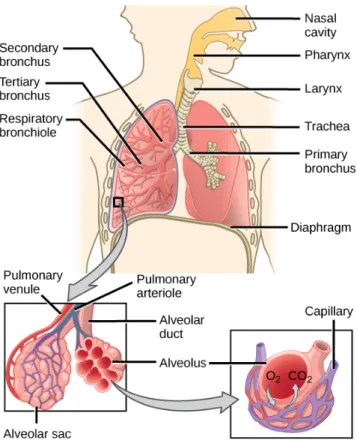
The lung is the major organ of the respiratory system, whose main function is the exchange of oxygen and carbon dioxide with air from the atmosphere. The human body has two lungs located inside the thoracic cavity, one at each side of the body. The left and right lungs are separated by the mediastinum (the central compartment of the thoracic cavity), which contains the heart, the trachea, the great arteries and major veins, among other structures. Each lung possesses an interface to the mediastinum which is called hilum. The hilum is the only point of access into the lungs, and is crossed mainly by the major bronchi and the pulmonary arteries and veins. Each lung is surrounded by the thoracic wall at the apex (top) and costal surfaces, by the mediastinum at the medial (central) surface and by the diaphragm muscle at the
base. Since the heart lies to the left of the body, the left lung is comparatively smaller than the right lung to accommodate for the needed space.
The fissures separate each lung into smaller units called lobes. The left lung is divided by the oblique fissure into two lobes, namely the superior and inferior lobes. The right lung is divided by the horizontal and oblique fissures into three lobes, namely the superior, middle and inferior lobes (see Fig. 1.1). Each lung lobe is further di-vided into anatomically and functionally independent units called segments. As it will be described later in this chapter, this functional independence allows the surgi-cal resection of isolated lung anatomisurgi-cal structures, with little impact to the remain-ing structures (Levitzky, 2007). The anatomical resections of an entire lung, lobe or segment, are respectively called pneumonectomy, lobectomy and segmentectomy.
Figure 1.1:Coronal view of gross lung anatomy. The heart is located below the
car-diac notch. Illustration taken from Anatomy and Physiology, OpenStax (2013).
The surfaces of lung and the thoracic cavity are lined with two thin membranes called pleurae, as illustrated in Fig. 1.2. The visceral pleura encloses the surface of each lung and penetrates deep within the fissures that separate the lobes. The parietal pleura covers the internal surface of the thoracic wall, the upper surface of the diaphragm and the mediastinum. For each lung, the two pleurae meet at the hilum, creating a potential space1called pleural cavity or pleural space. This space contains a small
amount of serous liquid that is secreted from the pleurae and serves to lubricate their surfaces. This lubrication permits the pleurae to slide one against the other by reduc-ing friction, hence preventreduc-ing trauma durreduc-ing breathreduc-ing.
1. In anatomy, a potential space is a space between two structures facing one each other, and being held together by pressure.
Figure 1.2:Pleural cavity and main lung structures. Illustration adapted from
Anatomy and Physiology, OpenStax (2013).
Airways
Air is conducted from the atmosphere into the lungs within the airways. It enters the body at the mouth or nose and finishes inside alveoli, which are small balloon shaped structures where gas exchange takes place. Air gets later expelled out of the lungs also through the airways. The section of the airways that extends from the larynx and branches out from the trachea is called the bronchial tree. It is a fractal-like tubular structure of 23 branching generations. From the trachea (generation 0), it first divides into the left and right main bronchi before entering the lungs at the hilum. Each main bronchi is divided into lobar bronchi (secondary bronchi), which are in turn divided into segmental bronchi (tertiary bronchi). Further divisions fol-low, giving rise to even thinner and shorter structures called bronchioles. Alveoli start to appear on the walls of the smallest respiratory bronchioles, completely cover the subsequent alveolar ducts and are clustered in alveolar sacs at the end of the bronchial tree (see Fig. 1.3).
Gas exchange
The human body needs oxygen in order to break down foods that allow its normal functioning. It also produces carbon dioxide as a byproduct of metabolism, which needs to be expelled from the system. Gas exchange refers to the intake of oxygen and the elimination of carbon dioxide through the process of breathing. It happens within the numerous alveoli of lung parenchyma via diffusion.
The main pulmonary artery carries deoxygenated blood coming from the heart into the lungs. This main artery first divides into the right and left main pulmonary arter-ies, and branches down from there to the very small capillaries that surround
alveo-Figure 1.3:Overview of air transport and gas exchange. Illustration taken from
Ar-teries and veins of the body, OpenStax (2013).
lar walls. The deoxygenated blood within these capillaries contains lower amounts of oxygen and higher amounts of carbon dioxide than the air inside alveoli. The differ-ences in relative pressures allow gas diffusion to happen. This is, gas concentration between the air and blood balance out. As a result, the carbon dioxide of deoxy-genated blood passes through alveolar walls into the the alveolus. Similarly, oxygen from air crosses alveolar walls into the bloodstream (see Fig. 1.3). This oxygenated blood flows from the capillaries to the pulmonary veins and into the the heart, where it gets pumped out to the rest of the body.
1.1.2 Mechanisms of breathing
Breathing, or ventilation, can be described as the movement of air into and out of the lungs. This airflow allows for gas exchanges to happen inside the numerous alveoli of lung parenchyma. Inhalation (the movement of air into the lungs) and exhalation (the movement of air out of the lungs) are the two main phases of a breathing cycle. These phases are dependent on the differences of pressure between the exterior and the interior of the lung, which are caused by the contraction and relaxation of the respiratory muscles.
Pressure relationships
Air, like other fluids, moves from a region of higher pressure to a region of lower pres-sure. Therefore, for airflow to exist, a pressure gradient between the exterior and the interior of the lungs must be established. In lung ventilation, three main pressures are of consideration: the atmospheric pressure; the pressure inside alveoli, called alveo-lar pressure and the pressure inside the pleural cavity, called intra-pleural pressure (see Fig. 1.4).
Figure 1.4:Principal respiratory pressures. Relative values with respect to
atmo-spheric pressure are shown within parenthesis. Illustration taken from Anatomy and Physiology, OpenStax (2013).
Atmospheric pressure is the pressure within the atmosphere of Earth. It is approx-imately 760 mm Hg at sea level, and decreases with increasing elevation. During breathing, the atmospheric pressure remains relatively constant. Therefore, when discussing breathing mechanics, it is customary to express pressure values with re-spect to atmospheric pressure. That is, a pressure lower or higher than the atmo-spheric pressure is represented by positive and negative values respectively.
Alveolar pressure is the pressure of air inside alveoli. A difference between alveolar pressure and atmospheric pressure is what allows airflow to occur. Hence, alveolar pressure varies throughout the breathing cycle. It goes from negative during inhala-tion, to positive during exhalainhala-tion, and it is zero when there is no airflow at the end of both phases.
The intra-pleural pressure is the pressure inside the pleural cavity. Like alveolar pres-sure, it also fluctuates throughout the breathing cycle. However, in normal condi-tions, intra-pleural pressure is always slightly negative (West, 2012), at approximately −4mm Hg. This negative pressure is mainly caused by the mechanical interaction between the lung and the chest wall. Indeed, during breathing, these two structures
are constantly pulling each other in opposing directions. On the one hand, the lung parenchyma has a strong tendency to collapse into itself, which is caused by the in-ward elastic recoil of distended alveolar walls. On the other hand, the outin-ward elastic recoil of the chest wall acts to expand the chest cavity. As a result, the chest wall holds the lung open, while at the same time, it gets pulled inwards by the lung.
In addition, the differences among the three pressures presented above are known as pressure gradients. There are three principal pressure gradients in lung ventila-tion: the transrespiratory pressure, the transpulmonary pressure and the transtho-racic pressure. The transrespiratory pressure is the difference between the alveolar pressure and the atmospheric pressure. It is responsible for actual airflow into and out of the lungs. The transpulmonary pressure is the difference between the alveo-lar pressure and the intra-pleural pressure. It is responsible for holding the alveoalveo-lar walls open during breathing, avoiding their collapse. The transthoracic pressure is the difference between the intra-pleural pressure and the atmospheric pressure. It represents the pressure needed to expand or contract the lungs and chest wall.
Mechanics of breathing
During breathing, the pressure within lung structures varies according to Boyle’s law. This law states that the volume and pressure of a gas within a closed system under constant temperature are inversely proportional. That is to say that increasing the space that can be occupied by the gas results in a decrease of gas pressure, and vice-versa. Boyle’s law is expressed as:
P1V1 = P2V2 (1.1)
where P1and V1are the pressure and volume of the gas at the initial configuration;
and P2and V2 are those at the final configuration.
Changes in lung volume are then necessary in order to establish the pressure gradi-ents required for airflow. However, alveoli (and hence the lung) are not capable of expanding themselves. They only expand passively in response to an increased dis-tending pressure across the alveolar wall (Levitzky, 2007). This disdis-tending pressure is generated by the contraction of the respiratory muscles during breathing.
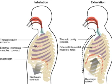
At the end of exhalation, all respiratory muscles are relaxed and pressure relation-ships are as depicted in Fig. 1.4. The alveolar pressure is zero, the intra-pleural pres-sure is negative and there is no airflow. From this resting state, a breathing cycle takes place: inhalation followed by exhalation to finally reach the initial resting state that prepares for the next cycle. A schematic representation of these inhalation and exha-lation phases is provided in Fig. 1.5.
Figure 1.5:Inhalation and exhalation phases of breathing. Illustration taken from
Anatomy and Physiology, OpenStax (2013).
Inhalation is an active process that involves the contraction of two groups of muscles: the diaphragm and the external intercostal muscles. On the one hand, the contraction of the diaphragm moves it away from the lung towards the abdominal cavity. On the other hand, the contraction of the external intercostal muscles pulls the rib cage upwards and outwards. As these muscles contract, the volume of the thoracic cavity increases and the pleural pressure becomes more negative. This drop in intra-pleural pressure rises the transpulmonary pressure gradient, which in turn pulls the lung open. This pressure gradient is transmitted to the interior of the lung, expanding alveolar walls (Levitzky, 2007). The volume increase of alveoli decreases alveolar pressure, establishing a negative transrespiratory pressure gradient that allows air to enter into the lungs. As alveoli get filled in with air, alveolar pressure increases until it reaches zero again at the end of inhalation.
Exhalation is a passive process that consists in the relaxation of the muscles con-tracted during inhalation. As the diaphragm and the intercostal muscles come back to their resting positions, the volume of the thoracic cavity decreases. This reduces the transpulmonary pressure gradient that was pulling the lung open. Alveoli then start to recoil and decrease in volume, which rises alveolar pressure above atmospheric pressure. A positive transrespiratory pressure gradient is then established, and air starts to flow out of the lungs. The resting configuration is reached again once the alveolar pressure has decreased to zero at the end of exhalation.
The inhalation and exhalation processes described above are executed unconsciously during normal breathing. However, conscious forceful inhalation and exhalation are also possible if bigger breaths are necessary. These two active processes require the contraction of additional muscles that help in exaggerating volume changes of the
thoracic cavity. These additional muscles are located primarily in the neck, thorax and abdomen; and are called accessory respiratory muscles given their secondary role during normal breathing.
Pneumothorax
As mentioned earlier, alveoli have a strong tendency to collapse that is caused by the inward recoil of their distended walls. During breathing, the transpulmonary pres-sure gradient is always positive, pulling the lung outwards and avoiding its collapse. This is mainly due to the negative intra-pleural pressure.
Under certain circumstances (e.g. perforation of the thoracic cavity after trauma or during surgery), an abnormal pathway of air can make the pleural cavity get in direct communication with the atmosphere. Consequently, air from the atmosphere rushes into the pleural cavity until intra-pleural pressure reaches atmospheric pressure. In such scenario, the transpulmonary pressure gradient is no longer positive, making the outward pull at the lung surface to disappear and ultimately resulting in lung collapse. This condition is called pneumothorax. An illustration of a pneumothorax is provided in Fig. 1.6.
Figure 1.6:Illustration of a collapsed lung after pneumothorax. Illustration adapted
from Blausen Medical (2014).
1.2
Lung cancer
Lung cancer is the worldwide leading cause of cancer death among both women and men (Bray et al., 2018). It accounts for more than 18% of all cancer deaths, claiming each year almost as many lives as do prostate, liver and breast cancer combined (see Fig. 1.7). In 2018, it is estimated that more than 2.1 million new lung cancer cases were diagnosed worldwide, and more than 1.8 million people died from the disease (Bray et al., 2018). In Europe, although tobacco regulation has helped decreasing