HAL Id: tel-02918135
https://tel.archives-ouvertes.fr/tel-02918135
Submitted on 20 Aug 2020
HAL is a multi-disciplinary open access
archive for the deposit and dissemination of sci-entific research documents, whether they are pub-lished or not. The documents may come from teaching and research institutions in France or abroad, or from public or private research centers.
L’archive ouverte pluridisciplinaire HAL, est destinée au dépôt et à la diffusion de documents scientifiques de niveau recherche, publiés ou non, émanant des établissements d’enseignement et de recherche français ou étrangers, des laboratoires publics ou privés.
eye display system for augmented reality
Jianming Yang
To cite this version:
Jianming Yang. Study and optimization of an optical see-through near to eye display system for aug-mented reality. Optics / Photonic. Université de Strasbourg, 2018. English. �NNT : 2018STRAD007�. �tel-02918135�
1
ÉCOLE DOCTORALE MSII (ED n°269)
LABORATOIRE ICUBE (UMR 7357)
THÈSE
Présentée par:
YANG JIANMING
Soutenue le 29 mars 2018
pour obtenir le grade de: Docteur de l’Université de Strasbourg
Discipline/ Spécialité: Electronique, Microélectronique, Photonique
CONFIDENTIAL THÈSE dirigée par:
M. Philippe Gérard Maître de conférences, INSA de Strasbourg
RAPPORTEURS: M. Alois Herkommer M. Thierry Lepine
Professeur, Université de Stuttgart
Maître de conférences, Institut d’Optique Graduate School AUTRES MEMBRES DU JURY:
M. Bruno Serio
M. Patrice Twardowski M. Joël Fontaine
Professeur, Université de Paris Ouest
Maître de conférences, Université de Strasbourg Professeur, INSA de Strasbourg
S
tudy and optimization of an optical see-through
near to eye display system for augmented reality
Acknowledgements
I would like to take this opportunity to express my appreciation and thanks for all the persons that gave me the encouragement and support, to reach this point in my academic career. I would like to greatly thank my principal advisor: Philippe Gerard for the help of using software and teaching me methodology. I would also like to pay my highest tribute to my co-advisor Dr. Patrice Twardowski for your kind and professional guidance. The correction of the thesis and articles has taken your many efforts. I would like to express my great gratitude to Prof. Joël Fontaine for your recognition, admission and guidance. Without you, I cannot begin a PhD in France.
I would also like to thank all the members of photonics instrumentation and processes team; especially, Dr. Sylvain Lecler for guidance on photonic nano-jet. Dr. Pierre Pfeiffer for measuring surface quality of our samples, Prof. Paul Montgomery for your English corrections, Dr. HALTER Eric for teaching me Français, Dr. Stéphane Roques for polishing help. I would also like to give a warm thank to all the colleagues from the Icube-IPP team. I would like to thank Ms. Marine Auvert from Société d'Accélération du Transfert de Technologies (SATT) who helped us to obtain financial support from SATT.
I thank my PhD committee: Prof. Bruno SERIO, Prof. Alois HERKOMMER, Dr. Thierry LEPINE who provided me with their time and attention to evaluate my work and give me very useful suggestions. I would also like to thank Dr. Bernard Kress for coming to my defense. Your suggestions would have a profound impact to me.
Finally and importantly, I dedicate very special thanks to my parents, whose love and support through my whole life has given me the passion to pursue my education. I would like also to express many thanks to Chinese schoolmate: LIU Chenchen for your many helps, YU Wenhui for ge.zhong.che.dan, YANG Xiucheng, LIU Guixian for ge.zhong.wan.shua, SUN Xiaoguang for ge.zhong.he.zui, YUAN Ye, ZHEN Xiaopo, TANG Shuangqi, WANG Xinyue, HU Ronghai, WANG Jian for shitang chifan and wanshua, TANG Fujiao and DING Yifan for zhaoxiang, LIU Yingdong, WANG Wen for help and many others.
3
List of abbreviations
NED Near to eye display
HMD Head mounted display
HWD Head-worn display
AR Augmented reality
VR Virtual reality
FOV Field-of-view
DFOV Diagonal field-of-view
HFOV Horizontal field-of-view
VFOV Vertical field-of-view
DOE Diffractive optical element
HUD Head-up display
EPE Exit pupil expander
TIR Total internal reflection
SBG Switchable Bragg Grating
FDTD Finite-Difference Time-Domain method
FEM Finite element method
PML Perfect matched layer
ASM Angular spectrum method
HFL Harmonic Fresnel Lens
RAP Right-angle prism
PNJ Photonic nano-jet
FWHM Full width at half maximum
Résumé
Récemment, les afficheurs placés près de l'œil (NED: Near to Eye Display) de type lunette pour la réalité augmentée (RA) sont devenus un sujet en vogue en raison de la sortie de certains produits commerciaux tels que Microsoft HoloLens et Google Glasses. Pour les systèmes de RA, ces dispositifs permettent aux utilisateurs de voir simultanément l'image virtuelle générée par ordinateur (information ajoutée) et la scène du monde réel; l’ensemble formant ce qu’on appelle la réalité augmentée. Les dispositifs de RA peuvent être utilisés dans de nombreux domaines d’application tels que l’aviation militaire, les systèmes de divertissement commerciaux et les systèmes de visualisation pour applications médicales. Plusieurs approches pour la réalisation de ces dispositifs ont été utilisées : des structures planaires semi-réfléchissantes, des systèmes hybrides réfractifs-réflectifs, des prismes à forme libre, une optique adaptative de correction, des systèmes de projection rétinienne et des guides d'ondes géométriques de type lunette (GWNED: Guided Waves Near to Eye
Display). Les GWNED sont constitués d'un sous-système appelé coupleur d’entrée (incoupler) qui
permet de coupler l’image générée par un ordinateur dans le ou les guides d’onde et d'un sous-système appelé coupleur de sortie (outcoupler) qui couple l’image propagée par le ou les guides d’onde vers l’œil du porteur de lunette. Le dispositif peut être monoculaire ou binoculaire suivant que l’on équipe un œil ou les deux yeux. Les coupleurs de sortie offrent l'avantage d'augmenter la taille de la pupille de sortie du système sans trop augmenter la complexité du coupleur d’entrée. De plus, ces structures sont très compactes. Pour le coupleur de sortie, la société Lumus utilise par exemple un réseau de miroirs partiellement réfléchissants. Cet ensemble est spécialement conçu pour avoir une réflectance adaptée aux différentes longueurs d'onde et angles d’incidence. La société Optinvent quant à elle utilise de petits miroirs en cascade pour le couplage de sortie. Zhao et al. ont introduit un micro-coupleur de sortie à haute visibilité utilisant des microstructures triangulaires. Les conceptions associées à ces systèmes sont principalement basées sur la simulation par tracé de rayons. Un autre type de coupleur de sortie utilise des éléments optiques diffractifs (EOD) ou des éléments optiques holographiques (EOH). Ces éléments se retrouvent dans les produits des sociétés Microsoft, Konica Minolta, Sony et BAE Systems. Pour le coupleur d’entrée, des lentilles de projection sont utilisées pour des système de type GWNED avec de petits champs de vision (FOV:
5
l'intérieur du guide d'onde. La conception combinant un prisme de forme libre et un guide d'ondes permet d’obtenir une valeur du champ de vision plus grande à l’aide de deux pupilles séparées. Cependant, le champ de vision vertical est aujourd’hui encore limité à environ 30 degrés.
Pour faire un NED efficace et utile, il faut réaliser un compromis entre les performances optiques, le poids et les dimensions. Jusqu'à présent, à notre connaissance, aucune conception ne peut répondre simultanément à toutes ces exigences. De nos jours, de nombreux types de NED existent avec des performances optiques différentes en termes de FOV et de volume de déplacement admissible pour l’œil VDAO (Eye-box). A titre d'exemple, pour les guides d'ondes de type NED, l'appareil Lumus OE-31 a un champ de vision avec une diagonale de 40 degrés et un VDAO de 10 x 8 mm.
1. Objectifs de la thèse
Les objectifs de la thèse sont les suivants :
➢ Concevoir de nouveaux systèmes qui peuvent améliorer les performances optiques des NED. ➢ Étudier les configurations géométriques des systèmes proposés.
➢ Étudier les propriétés optiques des systèmes proposés.
➢ Prouver le concept de manière expérimentale pour un système sélectionné. ➢ Étudier de nouvelles solutions pour des futures améliorations.
2. Description des travaux réalisés
2.1. Systèmes proposés basés sur des optiques à surfaces à forme libre
Pour atteindre les objectifs spécifiés ci-dessus, nous proposons le système représenté Fig. 1. La figure montre la structure du système et le trajet des rayons à l'intérieur des composants. Deux guides d'ondes sont empilés avec un petit espace d'air entre eux afin que la lumière puisse se propager à l'intérieur des deux guides d'ondes indépendamment. La lumière émise par le micro-afficheur est couplée dans le premier guide d'ondes par le coupleur d’entrée. La lumière se propage à l'intérieur du premier guide d'ondes jusqu'à atteindre un miroir cylindrique à l'extrémité du guide. Dans la zone
proche du miroir, les deux guides d'ondes sont combinés ensemble. Ensuite, la lumière réfléchie par le miroir cylindrique est couplée dans le deuxième guide d'ondes. Ce couplage a été étudié et optimisé. En utilisant des méthodes existantes telles que les hologrammes ou les miroirs en cascade, la lumière est couplée hors du deuxième guide d'ondes vers l’œil du porteur de lunette. Le système de couplage d’entrée se compose d'un prisme avec quatre surfaces optiques à forme libre différentes (de S2 à S5) et d'une lentille constituée d'une surface à forme libre (S1) et d'une surface plane. La pupille de couplage a une forme rectangulaire avec une taille de 1,9 mm (H) × 12 mm (V) qui agit comme un diaphragme d’ouverture et r é duit considérablement la lumière parasite. Le rayon principal de chaque champ passe par le centre de la pupille d'entrée du guide d’onde.
Après la réflexion par le miroir cylindrique, le rayon principal de chaque champ converge vers le centre de la pupille de sortie (œil) à travers le deuxième guide d'ondes et le coupleur de sortie. Ensuite, chaque champ peut être vu comme indiqué dans la Fig. 1(c).
Fig. 1. La structure entière et le chemin optique du système proposé avec différents points de vue : (a) vue
yx, (b)vue zx, (c)vue zy.
Nous avons proposé de nouveaux guides d'ondes polychromatiques NED avec un prisme de forme libre et des lentilles de forme libre. Les conceptions ont été réalisées avec le logiciel Zemax. Un micro-afficheur OLED de 0,61 pouce de diagonale avec 852×600 pixels a été utilisé comme source d'image. Le côté des pixels de forme carrée était de 15 μm, ce qui correspond à une fréquence de
7
Nyquist de 33 npl/mm. En conséquence, les valeurs horizontale et verticale du FOV étaient respectivement de 30° et 60°. Les valeurs de la FTM (Fonction de Transfert de Modulation) des champs objets étaient supérieures à 30% pour 33 npl/mm, ce qui est suffisant pour un système visuel. De plus, une très grande VDAO d'environ 10×8 mm permettant de grands mouvements oculaires a été obtenue.
Cependant, afin de réduire les contraintes sur le processus de fabrication et les tolérances, nous avons conçu et optimisé de nouveaux systèmes avec des lentilles à symétrie de rotation.
2.2. Systèmes proposés basés sur des lentilles à symétrie de rotation
Dans les propositions précédentes, comme le miroir cylindrique modifie la symétrie du système, des surfaces optiques à forme libre étaient nécessaires pour compenser l'asymétrie. La fabrication, le test et l'alignement des composants de surface à forme libre sont encore aujourd'hui un défi. C'est pourquoi nous avons conçu d'autres systèmes qui n'utilisent que des lentilles à symétrie de rotation comme coupleurs d’entrée. Pour maintenir les performances optiques, plusieurs prismes à angle droit (PAD) sur une base cylindrique ont été utilisés, au lieu d'un seul miroir cylindrique. Les PAD n'ont pas de puissance optique et peuvent rétroréfléchir la lumière incidente. De cette façon, le système est plus compact et la difficulté de fabrication du système est largement réduite. Une vue artistique est présentée à la Fig. 2. Les propriétés optiques (qualité d'image, efficacité énergétique, lumière parasite et tolérance) du système utilisant les PAD ont été étudiées en détail.
2.3. Résultats expérimentaux pour la structure du guide d'ondes
Nous avons défini et commandé la fabrication des deux guides d'ondes et de la pièce de transition avec des PAD. En raison de contraintes de temps, nous n'avons pas commandé les éléments du coupleur d’entrée, ni réalisé leur assemblage. Cependant, ce sous-système est une sorte d'oculaire qui peut transformer des sources ponctuelles objets du micro-afficheur en ondes planes qui sont couplées à l'intérieur du premier guide d'ondes. Pour cette conception, la partie critique et la plus importante est l’ensemble constitué des deux guides d'ondes empilés et couplés à l’aide des PAD.
Nous avons discuté de la tolérance de fabrication et du processus d'assemblage des trois composants. Ensuite, nous avons présenté les résultats de mesure avec le FOV, l'efficacité du couplage pour les ondes planes d'entrée, leur uniformité en intensité et le coefficient de transmission lié à la vue du monde extérieur. Les résultats ont prouvé la validité du concept de la structure à deux guides d'ondes. Pour protéger la propriété intellectuelle, un brevet international a été déposé. Il a été approuvé et publié en juillet 2017.
Afin de compléter l'étude des NED optiques, nous avons également étudié des conceptions alternatives utilisant des lentilles diffractives, plus précisément les lentilles diffractives harmoniques.
2.4. Simulation FDTD d’une lentille de Fresnel harmonique (LFH)
Pour réduire davantage le poids et la taille du système, on peut utiliser un élément optique diffractif (EOD). Par exemple, le coupleur d’entrée peut être remplacé par des EOD dont l'épaisseur peut être négligée. Comme nous sommes intéressés par un système polychromatique, un EOD qui peut fonctionner pour plusieurs longueurs d'onde est nécessaire. Une famille de EOD appelée lentille de Fresnel harmonique (LFH) permet un fonctionnement pour plusieurs longueurs d'onde spécifiques suivant le nombre harmonique choisi. Les publications sur ce sujet sont principalement axées sur les propriétés paraxiales des LFH. Toutefois, lorsqu'une LFH sert de composant dans le coupleur d’entrée, il faut tenir compte de ses propriétés non paraxiales, car la lumière peut avoir un angle d'incidence important. Afin d'obtenir des résultats précis, nous avons utilisé la méthode FDTD (Finite-Difference Time-Domain) pour simuler la performance à proximité de l'élément diffractif,
9
puis nous avons utilisé la projection en champ lointain pour calculer l'intensité du champ électrique dans l'espace libre. Le logiciel commercial Lumerical FDTD Solutions a été utilisé pour les simulations. La figure 3(a) donne un exemple de distribution de l'intensité du champ électrique à proximité d’une LFH et (b) la distribution additionnelle en champ lointain. De cette façon, nous pouvons traiter des géométries relativement grandes et évaluer les efficacités de diffraction.
Fig. 3. FDTD combinée à la projection en champ lointain
Cette étude a montré une façon prometteuse de réduire davantage le poids et la taille du coupleur d’entrée. Les LFH présentent l'avantage de bien fonctionner avec plusieurs longueurs d'onde discrètes pour une incidence normale. Nous avons étudié l'efficacité, la distance focale, l'intensité maximale au foyer et les dimensions de la zone focale (FWHM: Full-Width-Half-Maximum), largueur à mi-hauteur de l’intensité dans les deux directions, pour plusieurs nombres harmoniques et nombres d’ouverture. Nous pouvons en conclure que :
▪ Les longueurs d'onde harmoniques ne sont pas sensibles au nombre d’ouverture ;
▪ L'efficacité de diffraction et la FWHM de la zone focale augmentent au fur et à mesure que le nombre d’ouverture augmente ;
▪ La polarisation incidente a un effet négligeable sur l'efficacité, la distance focale, l'intensité maximale de la zone focale et la FWHM de la zone focale ;
▪ La dispersion normale des verres optiques a également un effet négligeable ;
raison des aberrations ;
▪ Avec un nombre d’ouverture plus grand, les LFH peuvent accepter des angles d'incidence plus grands.
▪ Les longueurs d'onde harmoniques sont également inchangées avec des angles d'incidence différents si les aberrations ne sont pas trop élevées.
En raison de ces propriétés, les LFH sont très prometteuses en tant que coupleurs dans les systèmes d’affichage de type lunette afin de les rendre plus compacts. Des études supplémentaires dédiées à l’utilisation de ces composants méritent d’être menées. Cependant, pour faciliter le travail de conception, certains modèles de surface spécifique adaptés aux LFH pour différentes longueurs d'onde devraient être développés pour les logiciels de conception optique commerciaux comme par exemple Zemax ou Code V.
Avant la simulation des LFH par FDTD, nous nous sommes formés sur différents systèmes optiques, notamment un système composé d'un cuboïde diélectrique noyé dans un cylindre diélectrique afin de générer un jet photonique ultrafin. Ce travail a fait l'objet d'une publication dans Optics Express .
3. Conclusion
Dans le cadre de cette recherche, nous avons proposé de nouvelles conceptions d’afficheurs proches de l'œil de type lunette pour la réalité augmentée. Nos conceptions peuvent augmenter le champ de vision vertical jusqu’à 60°, valeur presque deux fois plus grande que dans les systèmes de type guide d'ondes existants. Nous avons proposé des systèmes améliorés dans lesquels seules des lentilles à symétrie de rotation sont nécessaires. Les difficultés de fabrication et d'assemblage sont alors largement réduites. Les deux guides d'ondes et la pièce de transition avec des primes à angles droits ont été définis puis fabriqués. Nous avons caractérisé leurs propriétés géométriques et optiques. En mesurant expérimentalement le champ de vision, l'efficacité de couplage et l'uniformité en intensité, le concept proposé pour la structure à deux guides d'ondes a pu être validé.
Pour réduire davantage le poids, nous avons étudié ensuite les lentilles de Fresnel harmoniques, qui peuvent fonctionner avec précision pour plusieurs longueurs d'onde spécifiques, en utilisant la
11
méthode FDTD et la projection en champ lointain. Les propriétés optiques non paraxiales ont été étudiées. Pour gérer efficacement et finement les conceptions électromagnétiques, nous avons utilisé FEM de COMSOL. Nous avons aussi simulé un nano-jet photonique (PNJ) comme cas d'essai. La simulation d’un cuboïde diélectrique inséré dans un cylindre diélectrique a montré divers cas intéressants : un PNJ se focalisant à l'extérieur de la surface externe du cuboïde, un long jet photonique, la génération de modes de galerie et un effet de type jet photonique courbe (photonic
hook).
Pour concevoir un sous-système innovant comme coupleur de sortie, les métasurfaces semblent une voie très prometteuse. Leur conception devrait compléter nos résultats et mener à diverses solutions attrayantes pour les futurs afficheurs de réalité augmentée de type lunette.
Contents
1. Introduction ... 1
1.1. The study scopes ... 1
1.2. Motivation ... 2
1.3. Organization of thesis ... 2
2. Literature review ... 4
2.1. Augmented reality and see-through displays ... 4
2.2. Different classes of see-through AR NEDs ... 6
2.3. Key human factors considerations for NEDs ... 7
2.3.1. Optics of the eye ... 7
2.3.2. Eyes movements ... 10
2.3.3. The mode of vision ... 11
2.4. Review of NED optical designs ... 12
2.4.1. NEDs with free space combiner... 12
2.4.1.1. 45 degrees Flat combiner ... 13
2.4.1.2. Curved combiners with catadioptric system ... 15
2.4.1.3. Design with reflective surfaces only ... 20
2.4.1.4. One element system... 21
2.4.1.5. Diffractive free space combiner ... 23
2.4.2. Freeform prism NEDs ... 25
2.4.3. Waveguide NEDs ... 28
2.4.3.1. Diffractive waveguide ... 30
2.4.3.2. Holographic waveguide ... 34
2.4.3.3. Selective thin film array waveguide ... 36
2.4.3.4. Small mirror stripe array ... 38
2.4.3.5. Switchable Bragg Grating (SBG) out-coupling ... 39
2.5. Conclusion ... 40
3. Design of an in-coupling subsystem with freeform optics and a specific propagation subsystem ... 46
3.1. Background ... 46
3.2. Description of the complete system ... 49
3.2.1. Basic principle ... 49
3.2.2. Possible in-coupling techniques ... 50
3.2.3. Coupling light from the upper waveguide to the lower one ... 51
3.2.4. In-coupling subsystem with a free form prism ... 56
3.2.5. In-coupling subsystem with free form mirrors ... 58
3.2.5.1. Description of the system ... 58
13
3.2.5.3. Optical performance of the system ... 63
3.2.5.4. Tolerance of the system ... 65
3.2.6. In-coupling subsystem with freeform lens ... 67
4. NEDs with rotationally symmetric in-coupler ... 70
4.1. Geometry of the whole system ... 70
4.2. The rotationally symmetric in-coupler ... 71
4.3. Stray light analysis ... 73
4.4. Conclusion ... 77
5. Experimental results... 78
5.1. Fabricated components and their characteristics ... 78
5.1.1. Waveguides ... 78
5.1.2. Transition edge ... 82
5.2. Optical experiment results ... 84
5.3. Conclusion ... 87
6. Study of an in-coupling subsystem using a harmonic lens ... 89
6.1. Interest of harmonic lenses ... 89
6.2. Principle of the harmonic lens [18, 19]... 90
6.3. Optical properties of the HFL ... 93
6.4. Conclusion ... 100
7. Conclusion and perspective ... 103
Appendix A: Specifications of the Ocean Optics HL 2000 HP Source ... 106
Appendix B: Specifications of the Basler Scout-sc640-70fm camera ... 107
Appendix C: Fresnel reflective coefficients and coupling by evanescent waves .. 108
Appendix D: Harmonic Lens ... 110
List of Figures
Fig. 2.1. Taxonomy [1, 2]. ... 5
Fig. 2.2. Human visual system’s binocular field-of-view [26]. ... 8
Fig. 2.3. The schematic representation of the main axes of the human’s eye with the definition of the kappa angle – T: temporal and N: nasal [24]. ... 8
Fig. 2.4. Principle of the stereoscopic view and the vergence accommodation conflict. (a) Conceptual representation of accommodation within the same eye. (b) Conceptual representation of the VAC [27]. ... 9
Fig. 2.5. Principal geometrical and optical quantities for one eye [26]. ... 10
Fig. 2.6. Three ways of specifying FOV [28]. ... 10
Fig. 2.7. The basic structure of 45 degrees flat combiner. ... 13
Fig. 2.8. Alternative designs of 45 degrees flat combiner. (a) Kessler optics system and (b) Google glass [33]. ... 14
Fig. 2.9. (a) Schematic of a monocular head-mounted projection display and (b) Design of a compact p-HMHD prototype [35]. ... 14
Fig. 2.10. Basic configuration of the NEDs using curved combiner [37]. ... 15
Fig. 2.11. (a) Layout of the off-axis, 60-deg FOV HMD, (b) Distortion, (c) and (d) Plots of the polychromatic MTF for a 10-mm pupil size and various points in the FOV [40]. ... 16
Fig. 2.12. (a) Layout of the off-axis see-through HMD optical system, (b) Distortion, (c) Plots of the polychromatic MTF when lens 1 contains aspherical and (d) Plots of the polychromatic MTF when lens 1 contains x-y polynomial surface [41]. ... 17
Fig. 2.13. Layout of the HMD with two similar ellipsoids [42]. ... 18
Fig. 2.14. (a) Chief rays of just one ellipsoid. (b) Minimum distortion when an angle exists between an image plane and an object plane. (c) Structure of two ellipsoids. (d) Free grid distortion [42]. ... 19
Fig. 2.15. Structure of the HMD with freeform reflective mirror(FFRM) based on
15
7-pieces co-axis relay lens group, and an OLED [44]. ... 19
Fig. 2.16. (a)Optical layout of the reflective system (b) schematic diagram of
Immy Inc. product and (c) a picture of their product [45]. ... 20
Fig. 2.17. Comparison between NEDs with micro display and mobile phone panels
[Seer]. ... 21
Fig. 2.18. (a) Optical layout of design using large screen. (b) An example of
images produced by the optical system [46]. ... 22
Fig. 2.19. Products of Meta, Seebright and Seer [Meta, Seebright, Seer]. ... 22 Fig. 2.20. System contains DOE. (a) Lay out of the optical system, (c) The
products of Digilens (DL40) [48]. ... 24
Fig. 2.21. (a) An illustration of the setup and (b) Top view of the optical system
(not to scale). Q is a point of the plane of DOE 1, P is point of the plane of DOE 2 and I is a point of the plane of the virtual image. α1 is the angle
between the normal to DOE 2 and the direction (O1O2). α2 is the angle
between the normal to DOE 2 and the direction (OO2) [51]. ... 25
Fig. 2.22. Examples of products with freeform prism (a) MREAL HM-A1 (Canon),
(b) NED-X2 (NED+ Glass) and (c) Golden-I (Kopin). ... 26
Fig. 2.23. Layout of the see-through freeform prism system. ... 26 Fig. 2.24. (a) Layout of the Freeform prism lens system (b) Module of the
Freeform prism, (c) Polychromatic MTF plot of center field of the virtual imaging system, (d) polychromatic MTF plot of marginal fields of the virtual imaging system, (e) Distortion plots of the virtual imaging optical system and (d) Distortion plot of the optical see-through system [55]. ... 27
Fig. 2.25. Ergonomic designs using multiple reflection [56]. ... 28 Fig. 2.26. Principle of waveguide type designs for NEDs. (from National Physical
Laboratory) ... 29
Fig. 2.27. Diffractive waveguide: local diffraction efficiency, residual energy and
diffracted output energy with respect to the propagation distance [65]. ... 31
Fig. 2.28. (a) Layout of a two-dimensional EPE based on odd number of
of first-order diffractions [66]. ... 32
Fig. 2.29. (a) Perspective view of the waveguide using two overlapped DOEs as
out-coupler. H1 and H2 are overlapped in xy plane and separated by the thickness of the waveguide in z direction. (b) Optical path through this system [68]. ... 32
Fig. 2.30. (a)The asymmetric in-coupling grating divides the system in two
mirrored parts. The OE is usually also symmetric around the center line and if the illumination is done properly sequentially formed stereoscopic images can be shown. (b) Schematic presentation of the light path from illumination to the exit of EPE in a sequential stereoscopic NED [69]. ... 33
Fig. 2.31. Appearance of HoloLens and VUZUX’s AR3000. ... 34 Fig. 2.32. (a) A basic structure of a holographic waveguide with 3 reflective
holograms stacked together. Crosstalk within the holograms is shown. and (b) Two waveguides are used to minimize the crosstalk and oblique between the waveguide and the optical engine can reduce the Bragg λ disparity [72]. .. 35
Fig. 2.33. (a) Diffraction efficiencies characteristics of R, G, and B hologram
layers of the in-coupling hologram with respect to the incident angle. The thicknesses and index modulations of each hologram layer were approximately 5 µm and 0.04 respectively. (b) Diffraction efficiencies characteristics of R, G, and B hologram layers of the out-coupling hologram with respect to incident angle. The thicknesses and index modulations of each hologram layer were approximately 2 µm and 0.035 respectively [72]. ... 35
Fig. 2.34. Diffraction efficiencies of the out-coupling B and R hologram layers at
an incident angle of 50° [72]. ... 36
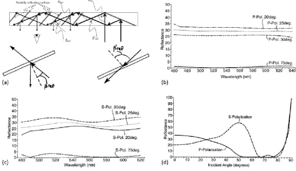
Fig. 2.35. Optical engine and development kits of Lumus [Lumus]. ... 36 Fig. 2.36. (a) (up) A side view of the waveguide having an array of selective
reflection coatings. (down) Alternative angular selective coatings. (b) The reflectance curves as a function of wavelength of an exemplary dichroic coating for P-polarization with incident angles of 20°, 25°, 30° and 75°. (c) The reflectance curves for S- polarization. (d) The reflectance curves as a
17
function of incident angle for an exemplary dichroic coating [73]. ... 37
Fig. 2.37. System using small mirror stripes. (a) monolithic light guide. (b)
monolithic light guide plus a “cover plate. (c) Optinvent ORA-2 [Optinvent]. ... 39
Fig. 2.38. An example of waveguide system using Switchable Bragg Gratings
(SBGs) [76]. ... 40
Fig. 3.1. (a) WGNED with one dimensional EPE. (a) xz view. (b) yz view. ... 46 Fig. 3.2. Definition of the geometrical parameters. ... 47 Fig. 3.3. Optical layout of the freeform eyepiece in (a) sagittal plane, (b)
three-dimensional view, (c) tangential plane. [2] ... 48
Fig. 3.4. Schematic for the designed system. (a) Ray path in zx plane. The dashed
rays are the rays that are coupled into the second (lower) waveguide. (b) Ray path in yx plane. The air gap is magnified for clarity. ... 49
Fig. 3.5. Two ways of coupling light into the waveguide. (a) direct coupling, (b)
coupling using a mirror. ... 51
Fig. 3.6. The ray tracing from the in-coupling pupil to the transition region. The
arrows inside the hatched region mean the ray hitting AB has upwards or downwards direction. ... 52
Fig. 3.7. The eight possible situations in the end of the two waveguides. The big
blue arrow indicates the direction when light hits AB. The green dashed sections represent successfully coupling cases. The red dashed sections represent the non-coupling cases. The pink rays with arrow show the critical geometry between coupling and non-coupling cases. ... 53
Fig. 3.8. Numerical Calculation results of the coupling from the upper waveguide
to the lower waveguide. (a) Minimum coupled energy Ecmin in all range of
with respect to the thickness of the upper waveguide d1 and the length of the
transition region T, (b) Ec with respect to when d1=2.72 mm and T=2.72
mm Three curves in different color represent theoretical value, simulated two cases w=0.7 mm and w=5 mm. ... 55
different points of view: (a) yx view, (b)zx view, (c)zy view. ... 56
Fig. 3.10. MTF curves of the system with the 12 evaluated fields in object angle mode. T and S represent the tangential and sagittal MTFs of each field separately. ... 57
Fig. 3.11. The grid distortion of the system with a maximum distortion of 4.5% at the corner. ... 57
Fig. 3.12. 3D structure and optical path of the system ... 59
Fig. 3.13. Different views of the proposed system. (a) yx view (b) zx view (c) zy view ... 60
Fig. 3.14. Optimization set up by using non-sequential waveguides and adding ideal thin lens ... 61
Fig. 3.15. Principle of replacing the waveguide by a medium of the same refractive index and an equivalent mirror ... 62
Fig. 3.16. Equivalent optimization setup (a) design from the user’s eye to the micro display (b) design from the micro display to the eye by adding an ideal thin lens ... 63
Fig. 3.17. Polychromatic MTF of the system. ... 64
Fig. 3.18. RMS spot radius field map. ... 64
Fig. 3.19. Grid distortion of the system ... 65
Fig. 3.20. The whole structure and optical path of the proposed system in different view. (a) yx view. (b)zx view. (c)yz view. ... 67
Fig. 3.21. (a) The polychromatic MTF of the 12 object fields of the system. (b) Grid distortion at the reference wavelength. ... 68
Fig. 4.1. Geometry of the system and ray tracing. (a) Perspective view, (b) yx view and the in-coupling lenses, (c) zx view with zoomed right-angle prisms, (d) yz view. ... 71
Fig. 4.2. Schematic diagram showing wearing effect in different views. (a) front view and (b) side view. ... 71
Fig. 4.3. Layout and optical performances of the in-coupling lenses. (a) raytracing,
19
and (d) Polychromatic MTF. ... 73
Fig. 4.4. Ray tracing through a right-angle prism in a plane. (a) single retroreflector function ray tracing, (b) ray tracing and stray light analysis of the set of RAPs (drawing not at scale). ... 74
Fig. 4.5. Stray light ratio with respect to number of half RAPs for r=40 mm, r=50 mm and r=60 mm when w=5 mm. Different colors represent different as shown in top right corner. ... 75
Fig. 4.6. Simulated result of stray light ratio with respect to incident angle. ... 76
Fig. 5.1. The two waveguides have been manufactured in three pairs. ... 79
Fig. 5.2. Dimensions of the manufactured waveguides (unit in mm)... 79
Fig. 5.3. Snapshots of the roughness measurements of the PMMA upper waveguide (a) put in reserve and (b) used guides. ... 81
Fig. 5.4. Snapshots of the roughness measurements of the Lumus glass waveguide (a) Outside the mirror area and (b) Inside the mirror area. ... 82
Fig. 5.5. Dimensions of the transition edge (unit in mm). ... 83
Fig. 5.6. Top angle measurement of some teeth. ... 83
Fig. 5.7. Surface roughness measurement of the transition edge in two locations. ... 84
Fig. 5.8. Experimental analysis for a single transition region. (a) Optical setup, (b) light output received at a distance about 5 cm. (c) light output received at a distance about 10 cm. (d) light output received at a distance about 15 cm. 85 Fig. 5.9. Setup for measurement. (a) Schematic diagram for the measurement and (b) Experimental setup for the normal incident white source intensity measurement. ... 85
Fig. 5.10. Optical response of the whole system. (a) illuminated with small angle without ambient light. (b) illuminated with small angle with ambient light. (c) illuminated with large angle without ambient light. (d) illuminated with large angle with ambient light... 86
Fig. 5.11. (a) A 5 mm prism with top and bottom surfaces unpolished and (b) hand polish setup and the polished surface... 86
Fig. 5.12. Optical response of the system with a 5 mm RAP. (a) direct observation
and (b) received by a screen... 87
Fig. 6.1. Modification of the height and width of grooves when the harmonic
number of a HFL increases, with a constant F/#=2. ... 91
Fig. 6.2. Principle of a harmonic lens with a harmonic number equals to ph. ... 92
Fig. 6.3. FDTD approach combines with far field projection for a HFL with ph=10, F#=1, D=400µm and =0.5 m. ... 94
Fig. 6.4. Optical properties of several HFLs with different F/# for unitary
s-polarized normal incident plane wave. The focus efficiency, focal length, maximum intensity and FWHM vs wavelength are plotted respectively. Each color represents a different harmonic number ph (a) F#=0.5, (b) F#=1 and (c)
F#=3. ... 95
Fig. 6.5. Raytracing of a HFL with F#=0.5. ... 96 Fig. 6.6. Electric field intensity distribution of a harmonic lens with ph=10. (a)
=0.49 m and (b) =0.52 m. ... 96
Fig. 6.7. Comparison between the result of paraxial approximation and FDTD plus
ASM. The harmonic number ph=9 in all cases. (a) Diffraction efficiency in
paraxial approximation and FDTD simulation for F/#=1, F/#=2 and F/#=3. (b) Comparison of the focal length as a function of wavelength. ... 97
Fig. 6.8. The maximum electric field intensity, the y position and x position of the
intensity maxima of several HFLs vs wavelength with different incident angle
. F/#=3 in all cases. (a) =1° (b) =3° and (c) =5°. ... 98
Fig. 6.9. Raytracing through lenses with design wavelength. (A) Aspherical lens
with F/#=1, raytracing of normal incident rays (blue) and with an incident angle =5° (green). (B) Fresnel lens with F/#=1. Incident angle is =5°. (C) Fresnel lens with F/#=3, Incident angle is =5°. ... 99
Fig. 6.10. Electric field intensity distribution of several cases when the incident
angle is =5°. The inserts are the zooming around the focal position. F#=1 in all the cases. (a) ph=1, =0.4µm, (a) ph=1, =0.5 µm, (a) ph=9, =0.54 µm
21
List of Tables
Table. 3.1. Performance of the system ... 58 Table. 3.2. Performance summary of the system ... 65 Table. 3.3. Tolerance criterion and result. ... 66 Table. 5.1. Measured dimensions and see-through transmittance of the upper guide.
... 80
Table. 5.2. Measured dimensions and see-through transmittance of the lower guide.
... 80
Table. 6.1. Numerical values of height and harmonic wavelength for a F/#=1 HFL
1. Introduction
1.1. The study scopes
The scope of the thesis is near to eye displays (NEDs) for augmented reality (AR). NEDs also known as Head Mounted Displays (HMDs) or Head-Worn Displays (HWDs). They are devices that can be worn by human and display information in front of the eyes. Some of them are for virtual reality (VR) by which only the virtual image is displayed, and the real environment is blocked. The others are for AR by which the real environment and virtual image are optically superimposed by see-through capability.
Recently, as the emergence of some commercial product for instance Google Glass, HoloLens and Oculus Rift. NEDs has become a very hot topic. Many companies are involved in this domain like Microsoft, Google, Facebook, Samsung, Lumus, Magic Leap, Optinvent, etc. Some of them are mainly focused on VR while others are on AR. However, there are still great challenges to overcome. High optical performance (large field-of-view, eye box, high resolution) in nowadays design implies increasing dimension and weight.
The element used inside a NED can be refractive, reflective and/or diffractive. New technologies such as metasurfaces are very promising because the existing architectures still have big limitations. However, the associated manufacture technologies are limited and costly. In this thesis, we have mainly focused our work on traditional optical elements which can be modeled by geometrical and scalar wave optics, with their associated tools: raytracing and MTF (Modulation Transfer Function) analysis. In order to evaluate new path in the design of in-coupler for future NEDs, in the final chapter, we have also investigated diffractive optical elements using a complete electromagnetic approach.
2
1.2. Motivation
The theme of the thesis for the author was originally motivated by chance (Choosing from several available research topics)! However, the continuity of the thesis is supported by the history and background of our lab as this is also a topic of a previous thesis. From a scientific point of view, the necessity of the research is due to the nowadays apparent contradiction between the optical performance and the compactness of the NED system. The existing NEDs are always cumbersome. The purpose of the thesis is to explore some new ways that may overcome the contradiction.
1.3. Organization of thesis
The content of the thesis will be organized into five chapters and a conclusion including perspectives for future works. In chapter 2, we firstly present an introduction about human eyes. Then we present a review about the nowadays architectures on NEDs. We classify all the NEDs into three families: NEDs with free space combiner, freeform prism and waveguide. In chapter 3, we present our several designs. All the designs involve a two-layer waveguide with a cylindrical edge. The main differences lie in the design of the in-coupler. Considering a cylindrical mirror as edge element, we describe three different in-coupler designs using respectively: a freeform prism, freeform mirrors and freeform lenses. In chapter 4, we introduce an improved design which also involves a two-layer waveguide but a different edge. The edge is composed of many right-angle prism (RAP) placed along a cylindrical base. The benefit is that we can have a rotationally symmetric in-coupler. All the proposed designs have been protected by an international patent (WO2017121967A3). In chapter 5, we present the preliminary encouraging experimental results related to the design described in chapter 4. In chapter 6, we consider a kind of diffractive optical element called Harmonic Fresnel Lens (HFL). The purpose of this study is the possibility of using HFL as a component inside the in-coupler to further reduce the dimension and weight. We use Finite-Difference Time-Domain (FDTD) plus Angular Spectrum method (AS) to
calculate the response of HFL accurately. Finally, we present the general conclusion and the future perspectives of this study.
1.4. Definition of terms
Field-Of-View (FOV): The FOV for a NEDs is the apparent angular size of the virtual
image seen by the viewer through the NEDs.
Eye box: In pupil-forming designs, exit pupil is more used than eye box, while in
non-pupil-forming system, eye box means the common area inside which we can see the whole FOV.
4
2. Literature review
This chapter introduces the fundamental concepts of see-through NEDs (Near to Eye Displays) from the perspective of optical design, image quality and field of view. Each NED design is application and user specific. After a short presentation of augmented reality and see-through displays, we begin by a summary of the human visual system and the key factors guidelines for the NED design and the user acceptance. Then we give an overview of the different approaches used in the optical design of NEDs. Finally, the quality of the display imagery presented to the user’s eye is discussed.
2.1. Augmented reality and see-through
displays
The paradigm of Augmented Reality (AR) aims at helping the interaction of the user with the real world (i.e. his physical environment, composed of physical objects) and the virtual world (i.e. data and processing means at his disposal) [1]. Milgram and his colleagues interpret augmented reality as being included in a linear continuum going from real to virtual [2]. They define the term of mixed reality as the spacing between real and virtual. This mixed reality contents augmented reality, but also augmented virtuality, which consists in integrating virtual elements into the real world. Dubois and his colleagues propose their own taxonomy [3] based on the task object and the type of augmentation (see Fig. 2.1).
Fig. 2.1. Taxonomy [1, 2].
Here we consider only see-though Augmented Reality displays where symbiology or imagery is optically superimposed into a see-through forward view of the user. The distinction between AR and virtual reality systems is very important because they are very distinctly different applications and then have very distinctly different performance requirements.
Since the 1960s, see-through AR displays known as HUDs (Head-Up Displays) have been developed for military applications especially military aircraft. For this class of displays, a collimator is placed in a fixed location in front of the pilot in order to display virtual information in the far field [4]. The transparent collimator does not obstruct the pilot’s view and is situated typically at 200-400 mm from the pilot’s eye. This distance, as we will show after, limits the field-of-view (FOV) of the system. Now HUDs have become standard equipment on many civilian airliners around the world [5]. They have been also introduced to automotive industry since the end of the 80s [6, 7]. This increasing use and success were leading researchers to consider see-through NEDs (Near-to-Eye Displays) also known as HMDs (Head Mounted Displays) or HWDs (Head-Worn Displays). They are also collimated virtual displays, but they are placed directly in front of one or both eyes of the user. They can be mounted on some type of helmet or glasses [8, 9]. Another proposed approach for HWDs has been the retinal scanning display. In this system, the displayed image is scanned directly onto the viewer’s retina with low-power blue, green and red lasers. The laser beams are modulated by acousto-optic modulators and then are coupled into fiber optics which
6
carry light to the helmet. Then the light reaches in free space propagation a pair of oscillating scanning mirrors which scan the viewer’s retina. [10]. The extreme case for a NED can be viewed as a contact lens with built-in information display [11, 12]. In following text, we do not consider the retinal scanning display and contact lens with information display because the optical design of these systems is based on completely different approaches. As reference books on HMDs we can cite the book of Melzer [13] more dedicated to NED development for fixed-wing aircraft, Reference [14-16] focused on the use of NEDs in U.S. Army rotary-wing aircraft. Specific chapters have been dedicated to NEDs [15, 17, 18]. A paper has reviewed the NEDs for the Next Generation Air Transportation System [19]. The history of NEDs can be found in ref [20].
2.2. Different classes of see-through AR
NEDs
According to the ocularity parameter, NEDs can be classified in monocular, biocular or binocular. In a monocular NED, a single image source is viewed by the sighting dominant eye (dominant monocular NED) or by the nondominant eye (nondominant monocular NED). Our dominant eye is the one we unconsciously choose when performing a monocular task. This effect has been recognized for centuries, but it remains poorly understood. Roughly 70% of the population shows a right-eye preference. This classification is based on the assumption that sighting dominance is a rigid preference. But it seems that it varies with different depth planes and with the position of objects relative to the eyes [21]. In a biocular NED, the same image source is viewed by both eyes. In a binocular NED, each eye views a different image source and with the right parameters, the viewer can see a 3D object [22]. The 3D object is plane for a fixed display distance but can be a volumetric 3D object with variable display planes.
image can be displayed at a fixed distance in the far field of the viewer, at a finite distance useful for some manipulation e.g. typically 500mm (distance from the eye to the end of the hand), or the virtual image is displayed in various planes at different distances [23].
2.3. Key human factors considerations for
NEDs
In this section we present shortly the optics of the eye and the three physiological processes: the accommodation, the vergence and the binocular parallax. Then the eyes movements and the mode of vision are described.
2.3.1. Optics of the eye
The instantaneous field-of-view of the human eye is roughly oval and typically measures 130° (V: Vertically) by 160° (H: horizontally) as shown in Fig. 2.2. The overall binocular FOV measures about 120°(V) by 200°(H). The eye is not a centered optical system. We can define rather two axes: the pupillary axis and the line of sight which can be considered approximately as the optical axis and the visual axis of the eye, respectively. The pupillary axis is the line perpendicular to the cornea that intersects the center of the entrance pupil. The line of sight connects the fixated object point to the center of the entrance pupil and the center of the fovea (see Fig. 2.3) [24]. The fovea is the retina area which provides the highest resolution. For instance, the normal resolution in the fovea is 1 minute of arc. As the incidence light angle increases the off-axis aberrations increase and the ability of peripheral retina to discriminate small objects decreases. And for example the resolutions at 10°, 20° or 30° of eccentricity are 2.5, 5, and 10 minutes of arc, respectively [25]. The average eye has an angle kappa of around 4° horizontally in the temporal direction and is centered vertically as shown in
Fig. 2.3, where is the angular distance (in the object space) between the line of sight and the pupillary axis.
8
Fig. 2.2. Human visual system’s binocular field-of-view [26].
Fig. 2.3. The schematic representation of the main axes of the human’s eye with the definition of the kappa angle – T: temporal and N: nasal [24].
In order to recognize 3D shapes, the eye and the brain use three physiological processes: the accommodation, the vergence and the binocular parallax.
Accommodation and vergence are cross-coupled in the neural control system and they interact dynamically. The accommodation is the ability of the eyes to focus on objects that are at different distances. The ciliary muscles change the refractive power of the crystalline lens by adjusting its shape in order to give from an object nearer than infinity, a sharp retinal image. For an object at the well-focused distance, the retinal image is the sharpest with minimum blur. As the depth of the object from the focused distance increases, the retinal image is increasingly blurred. In real world, due to the blur effects, accommodation and defocus blur are effective informative depth cue for relatively near objects typically less than two meters away. In vergence process, the two eyes rotate in opposite directions to maintain binocular fixation on objects at different distances. Inaccurate vergence leads to diploplia (double images). In stereoscopic NED
designs, the virtual image is focused at a fixed distance from the eyes while the depth of the virtual objects, and hence the binocular disparity, varies with the content, which results in conflicting information within the vergence-accommodation feedback loops which is called vergence-accommodation conflict (VAC) as shown in Fig. 2.4 [27]. Virtual display plane, or focal plane, is located at a fixed distance. The virtual objects can be located either in front or, if it is not at infinity, behind it. Thus, the disparity cue drives the eyes to verge at one distance, while the light rays coming from the virtual plane produce retinal blur, which drives the eyes to accommodate to another distance, giving rise to the conflict between these depth cues. Fig. 2.5 summaries for one eye, the different geometrical and optical quantities as the eye relief distance and field-of-view. Subscripts e, i, l, and s represent “eye”, “(virtual) image”, “lens”, and “screen” respectively, so terms such as dil explicitly denote “distance from image to lens”, wl
denotes “width of lens”; f is focal length; t is relevant for spatially-multiplexed MFP designs and represents the thickness of the display stack; M is the magnification factor from the physical to the virtual image. To allow viewing of the entire image, FOV must fit within the angular viewing range constrained by wl and lateral offset of the pupil,
which dictates the width of the eye box (we).
Fig. 2.4. Principle of the stereoscopic view and the vergence accommodation conflict. (a) Conceptual representation of accommodation within the same eye. (b) Conceptual representation of the VAC [27].
10
Fig. 2.5. Principal geometrical and optical quantities for one eye [26].
The Field-Of-View (FOV) for a HMD is the apparent angular size of the virtual image seen by the viewer through the HMD. A monocular FOV is what is viewed by one eye and a binocular FOV is the total angular size seen by the both eyes. In a NED, FOV and display resolution are linked by the focal length of the collimating optics. If we consider a given image source with a given number of pixels, a larger FOV will magnify the pixels more and then reduce the resolution that can be expressed in pixel per degree. There are three ways to specify FOV: (a) Horizontal FOV × Vertical FOV, (b) Diagonal FOV (DFOV) and (c) Total binocular FOV as shown in Fig. 2.6 [28].
Fig. 2.6. Three ways of specifying FOV [28].
2.3.2. Eyes movements
Human moves his eyes about three times each second via unconscious rapid eye movements (saccades) to reorient the fovea through the scene. 90% of viewing time is spent with the eyes apparently stationary, in fixations. These fixations have a duration of about 150-600 ms [29]. Human gaze is a combination of body position, plus head
and eye orientation. Total oculomotor range of eye movement in combination with head movement is ±55°. Without head movement, 90% of all the saccadic eye movements are within ±15°. Then a user who is forced to exceed the ±15° range may suffer eye strain and possibly miss a key piece of information [30].
Human balance ability is based on a combination of inputs from the proprioceptive, vestibular and visual systems. The proprioceptive system gives consciously or not information about the position of organs using the musculature, tendons and skeleton. The vestibular sensory organs are contained in the inner ear. The semicircular canals detect head rotational movements and the otoliths detect linear head acceleration. Then the vestibular system acts as a 6 degree of freedom motion sensor. The vestibulo-ocular reflex permits best vision during head motion by moving the eyes counter to head movement to stabilize the line of sight in space. This reflex allows the vision to lock onto an object even in presence of head motion or vibration. Vision contributes to our sense of balance and spatial orientation.
However, conflicting proprioceptive, vestibular and visual cues can result in spatial disorientation. Nevertheless, visual cues are capable to overriding conflicting inputs from vestibular cues, and wider fields of view contribute to a more stable posture and a better sense of balance. But display latency or other display artifacts can perturb the stabilization obtained by the vestibule-ocular reflex and create sickness (called cybersickness) with physical effects similar to motion sickness.
2.3.3. The mode of vision
The human visual system can be divided into two modes: the focal and the ambient modes. The focal mode is activated by the stimulation in the central portion of our vision. It is sensitive to light level, has a high resolution and rather answers to the question of “What?” about our environment. The ambient mode is generally found in the periphery of our vision. It is less sensitive to light level, has a lower resolution, is more susceptible to temporal effects such as movement and flicker and rather answers the question of “Where?” about our environment. Then for tasks requiring high
12
frequencies information, the focal vision should be activated by displaying NED or HMD imagery in the center of vision. If spatial orientation and balance are required for tasks in the real or virtual world, in that case, the ambient vision should be activated with a wide field of view imagery.
After a short presentation of key human factors that must be considered for NED applications, we detail different designs of NEDs that have been proposed in the scientific literature.
2.4. Review of NED optical designs
Morton Leonard Heilig was a pioneer in Head mounted displays(HMDs). He patented the first concept in virtual reality in 1960 [31]. In 1968, Ivan Sutherland created the first HMD system named The Sword of Damocles, with the help of his student Bob Sproull [32]. Since then, many kinds of Near to eye displays (NEDs) have emerged. Recently, Google started selling a prototype of Google Glass called "Glass Explorers" to the public in 2014, which makes the concept of augmented reality(AR) glasses popular. In the same year, Oculus released its pre-production model Oculus DK2, which aroused great interest for the virtual reality (VR) devices. In addition to these two products, many companies have their own designs. In this chapter, we will mainly focus on AR see-through near to eye displays (STNEDs). According to their structures, we separate all kinds of STNEDs into three families: free space combiner systems, freeform prisms and waveguide systems.
2.4.1. NEDs with free space combiner
In this section, we will introduce the NEDs with free space combiner. The combiner can be a flat mirror, curved mirror and diffractive optical element. The whole system can be a catadioptric optical system where refraction and reflection are combined in an optical system, usually with lenses (dioptrics) and curved mirrors (catoptrics) or purely reflective.
2.4.1.1. 45 degrees Flat combiner
This type is the most straightforward way to achieve see-through ability. The light from image source and the ambient are combined by the semi-reflective mirror as shown in Fig. 2.7. The size of the semi-reflective mirror and lenses increase as the FOV increases. The diameter of the first lens is:
) 2 tan( 2l FOV
D= ( 2-1)
where l is the distance to from the eye to the lens. Because of this relation, the system becomes very bulky when FOV is large. As an example, with FOV=30° and l=50 mm, the diameter of the first lens is 27 mm.
Fig. 2.7. The basic structure of 45 degrees flat combiner.
Alternative designs of this type are shown in Fig. 2.8 (a) from Kessler optics and Fig.
2.8(b) which is the optical system of Google glasses [33]. In Kessler’s system, a curved
mirror is added after the 45° planar mirror. In a sense, it may be classified into curved combiner as we will introduce in the next section. We still classify it into 45° planar combiner family because all the components are on-axis. The curved mirror has two functions. The first is to correct aberrations and the second is to reduce the size of the lenses. Even though the size of the curved mirror is also high, but normally mirrors are lighter than lenses with the same diameter. In the Google’s system, a curved mirror is also used, the difference is that the medium between the components is glass instead of air. This increases the weight of the system, the benefit of doing this is an easier
14
assembly. The drawbacks of adding mirrors is the energy reduction to less than 25% of the original energy. To improve the energy efficiency, a polarized beam splitter (PBS) has been used [34].
Fig. 2.8. Alternative designs of 45 degrees flat combiner. (a) Kessler optics system and (b) Google glass [33].
Polarized head-mounted projection display (p-HMPD) [35] can also be classified into this family. However, they can only be partially see-through. They involve a retro-reflector screen as shown in Fig. 2.9. The quarter-wave retarder and PBS are combined to increase the energy efficiency. The advantage of this structure is that a very small projection lens can be applied directly. The DFOV is around 50°-60°. However, the image quality of the retro-reflective screen is unsatisfactory under the current technical conditions.
Fig. 2.9. (a) Schematic of a monocular head-mounted projection display and (b) Design of a compact p-HMHD prototype [35].
combiner itself and the lenses due to its on-axis and rotationally symmetry. However, the size of the lens increases rapidly with the increase of the FOV. Generally, the FOV, eye box and the eye relief are small in this kind of system.
2.4.1.2. Curved combiners with catadioptric system
Applying curved combiners can improve the lighting budget of the system, and eliminate the ghost image. This kind of configurations provide the highest theoretical luminance transfer from the display with the highest see-through vision and increased eye clearances for a given FOV [36]. Fig. 2.10 shows the basic structure of the NEDs using curved combiner [37]. The whole system is an off-axis system. Thus, the main difficulties are to correct the off-axis aberrations. Normally, complex relay lenses are added. Freeform surfaces are suitable in this kind of system. However, as the difficulties and price of fabricating freeform lenses are high, the off-axis aberrations can also be well corrected by tilting and decentering several rotationally symmetric (spherical or aspherical) lenses. This phenomena can be explained by nodal aberration theory [38].
Fig. 2.10. Basic configuration of the NEDs using curved combiner [37].
Very good review in this family can be found in ref [9, 39]. Here we mainly focus on the performance and design details of this kind of system. Fig. 2.11 shows an off-axis design and its image quality and distortion [40]. In this design, the tilt of the combiner is 29.5° from the user’s line of sight. Astigmatism is the dominant image-degrading
16
aberration that is introduced by the off-axis configuration. The combiner in the system has a toroidal shape rather than spherical, to minimize third-order astigmatism. The relay lens contains two prisms to fold the optical system closely around the head of the HMD wearer, moreover, three non-spherical lenses are used: a cylindrical lens located in the second lens after the first prism and two parabolic lenses close to the second prism. To have the maximum image quality, the distortion is unconstrained as shown in
Fig. 2.11(b). What we can notice is that the tilted combiner also generates large
distortion. Fig. 2.11 (c) and (d) show the MTF for a 10 mm pupil size in different fields.
Fig. 2.11. (a) Layout of the off-axis, 60-deg FOV HMD, (b) Distortion, (c) and (d) Plots of the polychromatic MTF for a 10-mm pupil size and various points in the FOV [40].
Another example is shown in Fig. 2.12 [41]. The combiner (labeled 1) is a tilted spherical surface. Two flat mirrors (labeled 2) are used to fold the system snugly around the head of the user. Relay lenses (labeled 3) are used to bring forth the view image for the user and to compensate for the off-axis aberration between the image source and the combiner. The total of six relay lenses of the system consist of a positive meniscus lens, a biconvex lens, a doublet lens, a biconvex lens, and a positive meniscus lens, arranged sequentially in order from the combinerto the image source. The first lens, which is labeled 3′-lens1, has positive power, which can make it possible to reduce the diameter and thickness of the system. Lens1, consisting of an x-y polynomial surface
and a concave spherical surface, was bent to the combiner to reduce spherical aberration. Even order items of x in x-y polynomials were kept reducing the astigmatism aberration and asymmetric field curvature introduced by the tilted spherical combiner. Aspheric lens2 contributes mainly to limit coma. A cemented doublet was applied to the system to provide correction for distortion, axial color, and lateral color aberration. Lens3 with an aspheric surface has a 6.4° tilt to balance the residual astigmatism. Lens4 is a meniscus lens with positive power to limit distortion.
A comparison of MTFs when lens 1 contains aspherical surface or x-y polynomial is shown in Fig. 2.12 (c) and (d) respectively. With aspherical surface, 15% at a spatial frequency of 20 line pairs/mm across the full field is achieved while 30% at the spatial frequency of 30 line pairs/mm is achieved using the x-y polynomial surface. The maximum distortion is 10% at the top right corner of the field. The shape of the distortion is very like the first example [40].
Fig. 2.12. (a) Layout of the off-axis see-through HMD optical system, (b) Distortion, (c) Plots of the polychromatic MTF when lens 1 contains aspherical and (d) Plots of the polychromatic MTF when lens
1 contains x-y polynomial surface [41].
The off-axis aberrations are the main difficulties to overcome and distortion is more serious in this kind of systems. The main source of the aberrations and distortion is the tilted combiner. To reduce the influence of the combiner, we can put a compensator
18
which is similar to the combiner. Yang et. al designed a system according to this concept as shown in Fig. 2.13 [42].
Fig. 2.13. Layout of the HMD with two similar ellipsoids [42].
The principle of correcting the distortion is shown in Fig. 2.14. Fig. 2.14 (b) presents the minimum distortion when an angle exists between an image and object planes (known as the Scheimpflug condition) [43]. Such distortion is difficult to correct by simply placing refractive lenses around the second focus. To solve this problem, another ellipsoid with the same conic constant is used to offset the distortion caused by the first ellipsoid [see Fig. 2.14(c)]. The right focus of the left ellipsoid overlaps with the left focus of the right ellipsoid. Light emitted from focus A converge to focus B. Rays then converges to focus C because focus B is also a focus of the left ellipsoid. The two ellipsoids have the same conic constant. Thus, ΔADB ≈ ΔCEB, CE∥DA. In addition, an arbitrary angle α at focus A is equal to the corresponding angle β at focus C (i.e., α = β). Therefore, the image at FG forms a distortionless image at HL if no other lens exists. The grid distortion is shown in Fig. 2.14(d).
Fig. 2.14. (a) Chief rays of just one ellipsoid. (b) Minimum distortion when an angle exists between an image plane and an object plane. (c) Structure of two ellipsoids. (d) Free grid distortion [42].
This system can achieve a single channel field-of-view (FOV) of 120° × 120° with a 6 mm diameter eye box and 49 mm eye relief on the pupil axis. However, the system is complex because of the large FOV. Using the same concept, it can be simplified with reduced FOV [44]. The lay-out of the system is shown in Fig. 2.15. The author applies a freeform reflective mirror (FFRM) in the co-focal point of the two ellipsoids. It achieves a FOV of 40°×30°(H×V) and an eye relief of 60 mm. In addition, the average illuminations are higher than 80%.
Fig. 2.15. Structure of the HMD with freeform reflective mirror(FFRM) based on the two similar ellipsoids. It consists of two ellipsoid surfaces, an FFRM, a 7-pieces co-axis relay lens group, and an
20
The primary advantage of the Catadioptric system design is that the see-through quality is the best for the moment. It also provides the highest theoretical luminance transfer from the display. The key drawbacks are very complex optical designs, bulky structures, difficulties to assemble and to hold steady the reflective surfaces. In the next section, we will introduce the NEDs using only reflective surfaces.
2.4.1.3. Design with reflective surfaces only
Systems built up only with reflective elements present no chromatic aberration. Such a design [45] is shown in Fig. 2.16(a). Immy Inc. has used this approach and their schematic diagram and product are shown in Fig. 2.16 (b) and (c). However, in this kind of systems, off-axis geometrical aberrations are still serious. The FOV is limited when only three mirrors are used. Higher optical performances can be obtained by increasing the number of mirrors. However, this will increase the size of the whole system. At the same time, the optical alignment and assembly become more difficult.
Fig. 2.16. (a)Optical layout of the reflective system (b) schematic diagram of Immy Inc. product and (c) a picture of their product [45].
Inside the all reflective system, there is one family that uses only one mirror. This system has been developed recently, in relation with the application of large display


![Fig. 2.5. Principal geometrical and optical quantities for one eye [26].](https://thumb-eu.123doks.com/thumbv2/123doknet/14506711.720232/32.892.150.746.114.393/fig-principal-geometrical-optical-quantities-eye.webp)
![Fig. 2.17. Comparison between NEDs with micro display and mobile phone panels [Seer].](https://thumb-eu.123doks.com/thumbv2/123doknet/14506711.720232/43.892.177.714.587.931/comparison-neds-micro-display-mobile-phone-panels-seer.webp)
![Fig. 2.20. System contains DOE. (a) Lay out of the optical system, (c) The products of Digilens (DL40) [48]](https://thumb-eu.123doks.com/thumbv2/123doknet/14506711.720232/46.892.193.711.124.384/fig-contains-doe-lay-optical-products-digilens-dl.webp)
![Fig. 2.27. Diffractive waveguide: local diffraction efficiency, residual energy and diffracted output energy with respect to the propagation distance [65]](https://thumb-eu.123doks.com/thumbv2/123doknet/14506711.720232/53.892.232.657.118.431/diffractive-waveguide-diffraction-efficiency-residual-diffracted-propagation-distance.webp)

![Fig. 2.38. An example of waveguide system using Switchable Bragg Gratings (SBGs) [76]](https://thumb-eu.123doks.com/thumbv2/123doknet/14506711.720232/62.892.234.667.194.482/example-waveguide-system-using-switchable-bragg-gratings-sbgs.webp)

