Publisher’s version / Version de l'éditeur: Fire Technology, 45, 4, pp. 1-18, 2009-12-01
READ THESE TERMS AND CONDITIONS CAREFULLY BEFORE USING THIS WEBSITE.
https://nrc-publications.canada.ca/eng/copyright
Vous avez des questions? Nous pouvons vous aider. Pour communiquer directement avec un auteur, consultez la
première page de la revue dans laquelle son article a été publié afin de trouver ses coordonnées. Si vous n’arrivez pas à les repérer, communiquez avec nous à PublicationsArchive-ArchivesPublications@nrc-cnrc.gc.ca.
Questions? Contact the NRC Publications Archive team at
PublicationsArchive-ArchivesPublications@nrc-cnrc.gc.ca. If you wish to email the authors directly, please see the first page of the publication for their contact information.
NRC Publications Archive
Archives des publications du CNRC
This publication could be one of several versions: author’s original, accepted manuscript or the publisher’s version. / La version de cette publication peut être l’une des suivantes : la version prépublication de l’auteur, la version acceptée du manuscrit ou la version de l’éditeur.
For the publisher’s version, please access the DOI link below./ Pour consulter la version de l’éditeur, utilisez le lien DOI ci-dessous.
https://doi.org/10.1007/s10694-009-0116-6
Access and use of this website and the material on it are subject to the Terms and Conditions set forth at Mechanical characterization of fibre reinforced polymers materials at high temperatures
Chowdhury, R.; Eedson, R.; Bisby, L. A.; Green, M. F.; Bénichou, N.
https://publications-cnrc.canada.ca/fra/droits
L’accès à ce site Web et l’utilisation de son contenu sont assujettis aux conditions présentées dans le site LISEZ CES CONDITIONS ATTENTIVEMENT AVANT D’UTILISER CE SITE WEB.
NRC Publications Record / Notice d'Archives des publications de CNRC: https://nrc-publications.canada.ca/eng/view/object/?id=9e18437c-74bc-4c20-b8d4-d8ad73d2eb90 https://publications-cnrc.canada.ca/fra/voir/objet/?id=9e18437c-74bc-4c20-b8d4-d8ad73d2eb90
http://www.nrc-cnrc.gc.ca/irc
M e c ha nic a l c ha ra c t e riza t ion of fibre re inforc e d polym e rs m a t e ria ls a t high t e m pe ra t ure s
N R C C - 5 0 8 5 1
C h o w d h u r y , R . ; E e d s o n , R . ; B i s b y , L . A . ; G r e e n , M . F . ; B é n i c h o u , N .
D e c e m b e r 2 0 0 9
A version of this document is published in / Une version de ce document se trouve dans:
Fire Technology, 45, no. 4, pp. 1-18, DOI: 10.1007/s10694-009-0116-6
The material in this document is covered by the provisions of the Copyright Act, by Canadian laws, policies, regulations and international agreements. Such provisions serve to identify the information source and, in specific instances, to prohibit reproduction of materials without written permission. For more information visit http://laws.justice.gc.ca/en/showtdm/cs/C-42
Les renseignements dans ce document sont protégés par la Loi sur le droit d'auteur, par les lois, les politiques et les règlements du Canada et des accords internationaux. Ces dispositions permettent d'identifier la source de l'information et, dans certains cas, d'interdire la copie de documents sans permission écrite. Pour obtenir de plus amples renseignements : http://lois.justice.gc.ca/fr/showtdm/cs/C-42
Mechanical Characterization of Fibre
Reinforced Polymers Materials at High
Temperature
E. U. Chowdhury1, R. Eedson1, L. A. Bisby2, M. F. Green1, and N. Benichou3
1
Queen’s University, Department of Civil Engineering, Kingston, ON, Canada
2
BRE Centre for Fire Safety Engineering, University of Edinburgh, Scotland, UK
3
Fire Research Program, Institute for Research in Construction, National Research Council, Ottawa, Canada
Abstract. One of the greatest impediments to using fibre reinforced polymer (FRP) composites in buildings and parking garages is their susceptibility to degradation when exposed to elevated temperatures and the limited knowledge on the thermal and mechanical properties of these composites at such temperatures. Glass FRP (GFRP) tensile coupons and single lap-splice coupons were tested in tension to study the mechanical properties under steady-state and transient thermal conditions. Tests were conducted at a range of temperatures between room
temperature and +200°C. In terms of tensile strength, approximately half of the strength of the FRP was lost near the glass transition temperature of the epoxy resin matrix. However, 40% of the room temperature strength of the GFRP was still retained at 200°C. The lap-splice tests showed that the FRP-to-FRP bond strength was affected even more by high temperature exposure with 90% loss in lap-splice near the glass transition temperature. An analytical model is also presented in this paper characterizing the mechanical properties at elevated temperature, which in turn will be used in numerical fire endurance models developed by the authors.
Keywords: fire, mechanical properties, FRP, analytical model, concrete, high temperature
Introduction
Fibre-reinforced polymer (FRP) materials are increasingly being used in strengthening or rehabilitating reinforced concrete structures that need to sustain loads higher than originally considered in design, or have deteriorated from
damage such as electrochemical corrosion. In spite of many advantages of using FRPs, such as resistance to corrosion and ease of application; fire resistance remains a significant obstacle to strengthening structural members in buildings and parking garages because of these materials’ susceptibility to degradation of mechanical and bond properties at elevated temperatures. A research study is underway at Queen’s University, Canada in conjunction with the National Research Council of Canada (NRC) and industry partners to investigate the effects of fire on FRP strengthened concrete structures. As part of this research study, this paper presents test results to characterize the mechanical properties of glass FRP (GFRP) under various loading and thermal regimes, ranging from ambient temperature to 200°C. Although 200°C is lower than temperatures normally experienced in a fire, it represents temperature levels expected for an FRP strengthening system protected with external insulation [1]. Results from these tests are used to develop an analytical model to represent the mechanical behaviour of GFRP for subsequent use in predictive fire simulation software which is currently being developed by the authors.
Research Significance
Examining the performance of FRP strengthened reinforced concrete members by conducting full-scale standard fire tests is expensive and time consuming. As a result, a major component of this research study involves developing numerical models that can simulate the heat transfer within FRP strengthened concrete structural members at high temperature. To accurately simulate the behaviour of FRP strengthened concrete structures, a detailed knowledge of the thermal and mechanical behaviour of FRP materials at high temperature, which is extremely scarce for the specific FRP systems under consideration, is critical. Rational and defensible numerical models could considerably reduce the costs incurred in standard fire testing of full-scale specimens. In addition, the critical temperature above which the FRP composite will have inadequate structural strength remains unknown. Such information is important for setting defensible service temperature limits for these systems.
Experimental Procedure
FRP specimen fabricationUnder various loading and thermal regimes, FRP tensile and FRP single-lap-splice bond strength tests were conducted to determine mechanical and bond properties, respectively. Details of the specimens for the two types of tests are in given in Figure 1. The GFRP coupon specimens for pure tension tests were made from two plies of saturated unidirectional glass fabric (Tyfo SHE-51A). Two 725 mm × 725 mm glass fabrics sheets were cut and saturated with epoxy resin (Tyfo S resin), which was mixed as per the manufacturer’s data sheet. The two
saturated fabrics were then stacked on a glass plate with the longitudinal fibres oriented in the same direction in both fabrics. A second glass plate was then placed on top of the lay-up. The lay-up was then left undisturbed for 72 hours. In a similar manner, a single ply 725 mm × 725 mm GFRP panel was made to be used as tabs during testing of the GFRP specimens as to avoid failure near the grips.
After 72 hours, both the double and single GFRP panels were removed from the glass plates and were cured in an air-conditioned laboratory at ambient room temperature and relative humidity ranging between 35 to 45% for
approximately 28 days. Following the 28 days, four glass tab strips were cut from the single ply GFRP panel to match the width of the double ply GFRP panel. The four glass tab strips were bonded to both sides to the two edges of the panel using epoxy putty (Sikadur 30), which was mixed as per the manufacturer
specifications. The panels were again placed in between two glass plates and left undisturbed for at least 4 days. After curing, the GFRP panels were cut into 38 ± 2 mm wide FRP coupons using a wet, abrasive diamond blade. The FRP coupons allowed left to dry prior to testing.
Single lap-splice FRP-to-FRP bond specimens were fabricated in a similar manner. However, in making these specimens, two 390 ± 2 mm long glass fabrics having a width of 725 mm were saturated with epoxy resin, and then carefully placed in between the two glass plates such that the two fabrics overlapped each other by 50 mm. After removing the single lap-splice FRP panel from between the two glass plates and curing for 28 days, tabs were installed and the panel was cut into 38 ± 2 mm wide coupons for testing.
Test Conditions and Instrumentation
Both steady state (heat then load) and transient state (load then heat) thermal regimes were considered. Prior to the tension tests, thermal behaviour of the FRP was investigated by the authors. The mechanical properties and bond strength of the FRP materials are known to begin degrading at temperatures close to the glass transition temperature, , of the polymer resin component, which is typically between 65°C and 120°C [1]. The glass transition temperature, in general, is considered to be the midpoint of the temperature range over which the polymer changes from a stiff, solid state into a flexible, rubbery state. Hence, the tests presented in this paper were conducted at ambient temperature and at
temperatures near the resin’s . Prior to the tension tests, differential scanning calorimetry (DSC) and dynamic mechanical thermal analysis (DMTA) were performed on samples of the polymer resin to investigate the thermal behaviour of the polymer using two different techniques. Through DSC, the heat loss or gain from the resin was profiled as the resin was heated at a constant rate to determine the . Note that DSC is a thermal, rather than physical, test method. DMTA measures, among other parameters, the change in storage (elastic) modulus ( ) and the change in loss modulus ( ). was measured in this test by identifying a dramatic change in the elastic modulus corresponding to a peak in the damping behaviour as measured by tan ⁄ . DMTA is a physical test, and is therefore a more meaningful test method as compared with DSC when studying the mechanical response of FRPs at high temperature.
Based on the determined using DSC, the steady-state thermal condition tension tests presented herein were conducted on both tensile FRP coupons and single lap-splice FRP coupons at ambient temperature, 30°C and 15°C below , at , and 15°C above . Additional tests were conducted at 200°C to observe the material’s performance at temperatures well above . For the steady-state thermal conditions tests, the FRP specimens were heated in the custom fabricated thermal chamber shown in Figure 2 to the desired temperature at 10°C/min, held at the specified temperature for 15 minutes to stabilize, and then loaded at a
crosshead stroke rate of 3 mm/min to failure. This heating rate was chosen to simulate the heating that might be experienced by an insulated FRP strengthening system exposed to a standard fire, based on previous testing of full-scale FRP
strengthened and insulated RC members [1]. The hold period was chosen to ensure that the entire sample was at a uniform temperature when it was loaded. The crosshead stroke was chosen to be half of the rate prescribed for FRP coupon testing at ambient temperatures by ACI [2] to correlate with the rate at which the images were being captured for the PIV and photogrammetry analysis.
For the transient thermal condition tests, the FRP specimens were
subjected to a specified sustained load for 10 minutes under ambient temperature and then heated at 10°C/min until failure. For tensile coupon tests, the sustained load was chosen to correspond to the highest strength achieved by any of the five coupons tested under steady-state conditions at 200°C, to ensure failure of the coupons under transient conditions. For the FRP-to-FRP bond strength tests at high temperature, the lap-splice specimens were loaded to either 10%, 20%, 40%, or 70% of their room temperature tensile strength. No investigation on the
heating and loading rate, both of which may be important, has been conducted thus far.
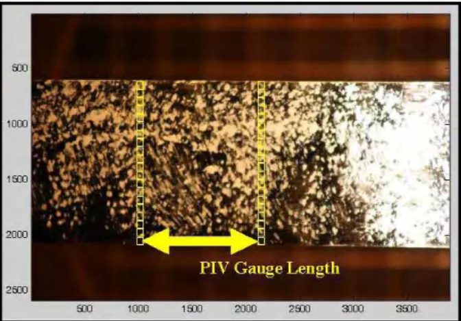
The tests were performed at elevated temperatures in an Instron Universal Testing Machine (UTM), which has a thermal chamber with an internal dimension of 250 mm (width) × 250 mm (depth) × 300 mm (height) and has a maximum load capacity of 600 kN and stroke capacity of 305 mm, Figure 2. Because of the well known difficulty of measuring strain at elevated temperatures during material testing, axial strains were measured using a unique deformation measurement technique based on particle image velocimetry (PIV) and close-range digital photogrammetry [3]. In this measurement technique, digital images were
captured of the FRP specimens inside the thermal chamber using a high-resolution digital camera. Using PIV, 20 virtual strain gauges were created across the width of the coupons by defining 40 pixel “patches” on the images of the FRP
specimens as shown in Figure 3. The gauge length of these virtual strain gauges was approximately 40 ± 10 mm. During PIV analysis, the digital images were processed to track the movement of the pixel patches and hence measure differences in the displacements of the patches between two or more digital images. Based on the displacements measured from the image processing, the axial strain was calculated at several locations across the width of the coupons. This information was subsequently used to calculate the elastic modulus of the coupons during testing as per ACI 440 requirements [2]. In addition to measuring
axial strains using PIV, the FRP specimens that were tested at ambient
temperature were instrumented with a 5 mm electrical resistance foil gauge to compare against the results obtained from PIV (Figure 4). All of the FRP specimens were also instrumented with two Type-K thermocouples on two different locations of the FRP surface (inside the thermal chamber) to observe the temperature distribution along the length of the FRP specimens.
Thermogravimetric analysis (TGA) was also conducted on the polymer resin, as well as on the bare fibres, and cured FRP, to observe the mass loss
response with increasing temperature. The TGA helped determine temperatures at which thermal decomposition or combustion of the materials occurred.
Analytical Models
There has been a broad interest in developing a generalized model for mechanical properties of FRP composites at high temperature. In recent years, research studies [4-9] have shown that the typical relationship between a mechanical property of a polymer composite and temperature under isothermal condition (that is, constant temperature throughout the material) is generally that shown in Figure 5. Since limited data exist on individual mechanical properties, such as modulus and strength, it is assumed for convenience that all mechanical properties can be fitted to the typical mechanical property versus temperature relationship shown in Figure 5. This analytical model assumes no significant change in the initial room temperature value of the mechanical property
until it reaches a critical softening temperature , above which the mechanical property decreases with increasing temperature to a residual value of , at which point the polymer composite has achieved a melting temperature of . The mechanical property deceases beyond the critical softening temperature , because the polymer composite’s polymer matrix begins to change from a hard and brittle state to a viscous or rubbery state over the glass transition region. As previously discussed, the glass transition temperature of a polymer composite is often determined by either DSC or DMTA, and it is important to be aware of the nature of these tests and the meaning of their outcomes, which can sometimes differ considerably for the same polymer resin, when using to set thermal performance limits for FRPs at high temperature. Beyond the temperature , the mechanical property decreases gradually. Research [4, 6] has shown that many
polymer composites lose more than 50% of their mechanical properties before reaching . Hence, it is appropriate to describe the relationship between mechanical properties and temperature of a composite using the thermal properties of the polymer.
A number of mathematical functions have been explored by researchers to describe the mechanical property versus temperature relationship shown in Figure 5. Kulkarni and Gibson [7] described the variation of the mechanical property with increasing temperature using a polyn mial expression as shown in Eqn-1: o
Eqn‐
where is a particular property at temperature , is the value of that property at room temperature , and , , and are fitting constants. This empirical relationship requires deducing the fitting constants , , and for various configuration and types of FRP material by performing small-scale fire tests of FRP materials.
Another model was derived from a physical basis by considering the effects on intermolecular bonds in the resin with increasing temperature [6, 8, 9]. There are two major types of bonds in polymers – primary and secondary. With increasing temperature, the primary bonds (which include the strong covalent intermolecular bonds) remain intact from glass to viscous state. The polymer undergoes transition when there is breakage or failure between the secondary bonds (such as, hydrogen, dipole, Van der Waals). Research studies [6, 8, 9] have derived an exponential relationship (Eqn-2) based on the effects of increasing temperature on these intermolecular bonds in the polymer resin. The model follows a Weibull di tr bus i tion as a function of temperature:
exp Eqn‐
where, is the Weibull exponent having a value ranging between 15 and 21. Mahieux and Reifsnider [8] validated Eqn-2 successfully by fitting to modulus versus temperature data.
Further investigation was conducted by Gibson et al. [5] on the effects of increasing temperature on intermolecular bonds by investigating a number of empirical equations to describe the mechanical behaviour of FRP composites. They found that the behaviour of FRP composites at elevated temperature can be
h b ent n [4, ]
well described by functions based on yper olic tang functio 5, 6 :
· · tanh · Eqn‐
where, km is an empirical constant describing the severity of the property
degradation with increasing temperature, Tcentral is the temperature around which
the curve is nearly symmetrical, and is a power law modification factor to account for resin decomposition. equals 1 when there has been no loss from decomposition and zero when the resin has been completely volatized. It should be noted that the indicated in Eqn-3 and Figure 5 is not necessarily equal to the glass transition temperature.
Results and Discussion
Physical and Mechanical PropertiesResults from the thermal analysis of the FRP specimens are shown in
Figure 6. The glass transition temperature of the FRP material was determined to be 75 ± 2°C based on DSC (where was determined on the second heating cycle) and 55°C based on DMTA. During DSC, the resin specimen went through a heating and cooling cycle; the specimen was heated to 150°C, cooled to 0°C, and then heated again to 150°C. Figure 6(b) shows results from the second heating cycle. Based on the measured values obtained from DSC, test temperatures were selected on the basis of recommended service temperature limits as per ACI 440 requirements [10] as 20°C (ambient), 45°C ( – 30°C), 60°C ( – 15°C), 75°C ( ), 90°C ( + 15°C) and 200°C. From the TGA, the FRP composite and the resin polymer began to lose their initial room temperature mass at about 360°C; however, the fibres showed no significant loss in their mass during the TGA, as expected. Around 500°C, the FRP composite and the polymer resin lost about 50% and 93% of their initial room temperature mass, respectively. During the DMTA, a sharp decrease in the resin’s elastic modulus was observed at about 35°C, and the resin lost 50% of its initial modulus at approximately 48°C.
Also, there was a dramatic change in the damping loss factor tan ) at about 55°C, thus identifying the of the resin polymer.
Five tensile tests were performed under steady-state thermal conditions at each of the above temperatures. Figure 7 shows the stress-strain plots of GFRP tensile coupons at room temperature. Axial strains in the coupons were measured using PIV analysis. The strain analysis was performed using twenty virtual axial strain gauges across the width of the coupons, and the axial strains were observed to vary by up to 0.5% across the width of the FRP coupon specimens at failure of the coupons. This variation can be attributed to non-homogeneities in the
coupons, as well as uneven gripping at the ends of the coupons. This indicates that results from coupon tests using wedge action grips and an isolated strain gauge to measure axial strain should be viewed with caution. Also shown in Figure 7 are the strains measured by a foil gauge bonded on the FRP specimen at the centreline, which is used to validate the optical technique. Good agreement is obtained between the foil and optical gauges since the foil gauge measurements fall within the range of variation of the optical measurements across the width of the coupon. The foil gauge on FRP tensile coupon Specimen 2 may not have been aligned properly along the length of the FRP coupon and as a result the foil gauge on the coupon specimen recorded lower strains than the optical gauges.
Additional validation of this optical technique for measuring strains in FRPs is given by Bisby et al. [11]. Despite the variation in observed axial strain over the coupon width, the axial strains from all 20 virtual strain gauges were averaged across the width to obtain a global stress-strain curve for the coupon. From this global stress-strain curve, the tensile chord modulus was calculated using stress values corresponding to 0.1% and 0.3% strain [3]. At room temperature, the GFRP coupons had an average tensile strength of 412 ± 22 MPa and an average tensile elastic chord modulus of 18800 ± 1800 MPa, based on a nominal thickness of 2.6 mm (which is the nominal thickness of two layers of FRP).
Figure 8 and Table 1 show the normalized tensile strength and elastic modulus data with increasing exposure temperature. The GFRP coupons tested in this paper experienced tensile strength losses of about 50 ± 9 % (average ± one standard deviation) and losses of tensile elastic modulus about 70 ± 13% at 60°C or – 15°C. Comparable losses of strength and modulus were observed at 75°C ( ), 90°C ( + 15°C) and 200°C, with little apparent additional degradation in
either strength or stiffness at these higher temperatures. This behaviour is likely due to loss of interaction and load sharing between fibres for all elevated
temperature exposures, due to matrix softening, such that the elevated temperature strength and stiffness values effectively represent the results that would be
obtained by testing dry fibres without a resin matrix. The data also suggest that, with adequate anchorage maintained at low temperature, the GFRP strengthening system tested herein can retain at least 40% of its room temperature strength at temperatures up to 200°C. Additional testing is needed above 350°C, where the matrix component of the FRP begins to decompose rapidly, Figure 6.
While considerable variability exists in the data shown in Figure 7 and
Figure 8, it should be noted that none of the coupons failed near the grips. All the coupons that were tested above 60°C ( – 15°C) ruptured in the region of the FRP that was inside the thermal chamber, indicating that the reduced strength and stiffness was not a consequence of thermal degradation in the gripping region. There were a few coupons below 60°C ( – 15°C) that failed outside the thermal chamber but away from the grips at 45°C ( – 30°C), which is assumed to be a random phenomenon not associated with thermal exposure. Failure of the GFRP coupons at room temperature was sudden and violent, Figure 9. The failure mode for coupons tested at 45°C ( – 30°C) and 60°C ( – 15°C) was similar to the failure mode observed at room temperature, but was less violent at the higher temperatures. However, with increasing temperature above 75°C ( ), the coupons split longitudinally (refer to Figure 10) as they approached failure and thus failed much more gradually. This splitting behaviour is thought to be associated with loss of interaction between the individual fibre rovings due to resin softening at elevated temperature.
To investigate the behaviour of the GFRP coupons under transient thermal conditions, five coupons were subjected to a sustained axial stress of 203 MPa, which corresponded to the highest strength achieved by one of the five coupons tested at 200°C under steady-state thermal conditions and also approximately 50% of the room temperature average strength. The coupons were then exposed to increasing temperature. Failure occurred in the GFRP coupons at 57 ± 3°C at a strain of 1.42 ± 0.07%.
FRP-to-FRP Bond
Figure 11, Table 2 and Table 3 show the normalized lap-splice bond shear strength data with increasing temperature under both steady-state and transient thermal conditions. The average FRP-to-FRP bond shear strength achieved by the single lap-splice GFRP specimens at room temperature was 9.2 ± 1.1 MPa. With increasing temperatures, the single lap-splice GFRP coupons experienced shear strength losses of 30 ± 8% at 45°C ( – 30°C) and 77 ± 1.3 % at 75°C ( ) under steady-state conditions. Comparatively, under transient conditions, the single lap-splice GFRP coupons experienced shear strength losses of approximately 29% at 54 ± 2°C and 80% at 71 ± 1°C. Little additional degradation was observed in the shear strength of the lap-splice beyond . The residual shear strength was about 16% and 10% of the average room temperature shear strength of the lap-splice under steady-state and transient conditions, respectively. All the coupons that were tested at elevated temperatures failed in the lap-splice region inside the thermal chamber as shown in Figure 12.
Based on the results from the two types of mechanical tests, the bond strength of the FRP lap-splice is more critical when designing FRP strengthened reinforced concrete members in a fire situation because the degradation of the lap-splice bond shear strength is considerably more severe than degradation of the FRP’s tensile strength with increasing temperature. This occurs because the FRP-to-FRP bond strength depends largely on the strength of the resin matrix which is much more susceptible to elevated temperature than the fibres. As the resin matrix degrades in the GFRP tensile coupons, the load is transferred to the fibres; thus the GFRP tensile coupons were able to retain more than 40% of their room temperature strength at 200°C.
Implementation in Structural Fire Model
As previously mentioned, the long term objective in performing the tests presented above is to develop empirical/analytical relationships to describe the variation in mechanical and bond properties of various currently available FRP strengthening materials and systems with temperature for subsequent use in numerical fire simulation models. The authors have, on the basis of previously
published research on the high temperature performance of polymer composites [4, 5, 6, 7, 8, 9], selected a sigmoid curve based on a hyperbolic tangent function [4, 5, 6] to describe the mechanical and bond property degradation of GFRP composites. In this study, was taken to be 1.0 because, based on TGA, the
resins do not experience any significant amount of decomposition until 350°C and was the average of the observed values of the property at room
temperature. Hence Eqn-3 becomes:
Using a non-linear multi-parameter least squares regression analysis, the terms , and, in the above equation were determined to provide an
approximation to the experimentally observed behaviour. Based on the values obtained from the regression analysis, the sigmoid curves for the mechanical and lap-splice bond properties are plotted on Figure 8 and Figure 11. After performing the regression analysis, the term was approximately the average value of the property at 200°C. The values of are presented in Figure 8 and Figure 11. Under transient conditions, the degradation of the FRP-to-FRP bond strength is slightly severe than under steady-state conditions (refer to Figure 13). Based on the regression analysis, was found to be between 47°C and 52°C for the strength, stiffness, and lap-splice bond properties under steady-state conditions, whereas, under transient state condition, was found to be 58°C for the FRP-to-FRP bond properties. It is significant that the range of values obtained for
from regression analysis was close to the temperature (47°C) where the polymer lost 50% of its initial elastic modulus during DMTA. This indicates that it may be possible to use the storage modulus loss curve from DMTA as a proxy for lap-splice bond degradation in externally-bonded FRP strengthening systems. Once the analytical relationships are derived for strength, stiffness and bond properties, they will be incorporated into numerical models to predict the fire endurance of GFRP strengthened reinforced concrete columns. However, further tests and investigations are required on different FRP composites at elevated temperatures to recommend a range of values for and to determine whether DMTA could be used to rationally estimate a priori. Tests on the bond between FRP and concrete are also required.
Summary and Conclusion
This paper presents the results of an ongoing experimental study aimed at developing a more complete understanding of the degradation in mechanical and bond properties of FRP strengthening systems for infrastructure at elevated temperatures. Based on the results of these tests on GFRP coupons, the following conclusions can be drawn:
• The wet lay-up glass/epoxy FRP material tested in this paper experienced 50% loss in tensile strength, 30% loss in tensile elastic modulus, and 60% loss in FRP-to-FRP bond strength at temperatures 15°C below the glass transition temperature of its resin matrix.
• Based on the data presented herein, the wet lay-up GFRP materials, with sufficient anchorage, can maintain 40% of their tensile strength and 70% of their elastic modulus at temperatures well in excess of the glass transition temperature of their resins. Much of the mechanical and FRP-to-FRP bond property degradation occurred below the glass transition temperature. However, the degradation of the FRP-to-FRP bond strength was more severe than the deterioration of the tensile strength and modulus. Approximately 90% of the FRP-to-FRP bond strength was lost at
temperatures slightly above the glass transition temperature. These results should be taken with caution because they represent the most severe possible test of FRP-to-FRP bond strength and are not representative of longer FRP bond/splice lengths used in practice. Thus, more research is required to investigate longer bond lengths and to determine the
consequences for member performance in fire.
• The loss of strength and stiffness appears to be due to loss of load-sharing between the individual fibre rovings, essentially resulting in dry fibre behaviour at temperatures close to or exceeding the glass transition temperature of the resin.
• The hyperbolic tangent function model in Eqn-4 presented herein is able to describe the mechanical and bond property degradation satisfactorily. However, considerable amount of additional testing is required before the true behaviour of FRP strengthening systems, under load, at elevated temperature can be accurately and reliably described.
References
[1] Bisby, L.A., Green, M.F., and Kodur, V.K.R. (2005). Response to fire of concrete structures that incorporate FRP. Progress in Structural Engineering and Materials, 7(3): 136-149.
[2] ACI (2004). ACI 440.3R-04: Guide test methods for fiber-reinforced polymers (FRPs) for reinforcing or strengthening concrete structures. American Concrete Institute, Farmington Hills, MI.
[3] White, D.J., Take, W.A., and Bolton, M.D. (2003). Soil deformation measurement using particle image velocimetry (PIV) and photogrammetry. Géotechnique, 53(7): 619-631.
[4] Feih, S., Mouritz, A.P., Mathys, Z., and Gibson, A.G. (2007). Tensile strength modeling of glass fiber-polymer composites in fire. Journal of composite
materials, 41(19): 2387-2409.
[5] Gibson, A.G., Wu, Y.S., Evans, J.T., and Mouritz, A.P. (2006). Laminate theory analysis of composites under load in fire. Journal of Composite Materials, 40(7): 639-657.
[6] Mouritz, A.P. and Gibson, A.G. (2006). Fire properties of polymer composite materials. Springer, The Netherlands.
[7] Kulkarni, A.P., and Gibson, R.F. (2003). Non-destructive characterization of effects of temperature and moisture on elastic moduli of vinyl ester resin and E-glass/vinyl ester resin composite. Proceedings of the American Society of Composites, 18th Annual Technical Conference, Florida, 19th-22nd October. [8] Mahieux, C.A., and Reifsnider, K.L. (2002). Property modeling across transition temperatures in polymers: Applications to thermoplastic systems. Journal of Materials Science, 37(5): 911-920.
[9] Mahieux, C.A. and Reifsnider, K.L. (2001). Property modeling across transition temperatures in polymer matrix composites: Part 1: Tensile properties. Polymer, 42(7): 3281-3290.
[10] ACI. ACI 440.2R-02: Guide for the design and construction of externally bonded FRP systems for strengthening concrete structures. American Concrete Institute, Farmington Hills, MI.
[11] Bisby, L.A., Take, W.A., and Caspary, A. (2007). “Quantifying strain variation in FRP confined concrete using digital image analysis. 1st Asia-Pacific
Conference on FRP in Structures (APFIS 2007), Hong Kong, December 12th-14th: 599-604.
Table 1: Tensile strength and modulus of GFRP coupons under steady-state conditions Temperature (°C) FRP Width (mm) Tensile Strength (MPa) Tensile Modulus (GPa)
Test value Average
Test value Average 20 37.4 415 18970 37.8 388 410 16120 18800 37.3 434 ± 21190 ± 37.8 431 20 19140 1800 37.6 391 18330 45 38.4 340 20380 38.2 412 325 18640 16900 38.1 301 ± 15120 ± 37.6 273 55 16930 2700 37.8 290 13590 60 38.0 246 16180 38.0 207 210 13920 13100 37.0 207 ± 13530 ± 37.8 232 35 12430 2500 37.2 154 9440 75 38.4 225 16070 38.6 226 195 12790 14400 38.5 183 ± 13450 ± 37.4 160 30 15780 1400 37.7 186 14060 90 38.0 216 15290 38.8 177 180 13830 11700 37.6 150 ± 13840 ± 38.1 196 25 9180 3700 37.4 167 6550 200 38.1 203 17260 37.8 195 190 14530 15300 37.8 190 ± 16020 ± 38.0 178 10 16310 2000 37.8 179 12170
Table 2: Shear strength of lap-splice GFRP specimen under steady-state conditions Temperature (°C) FRP Width (mm) Shear Strength (MPa) Test value Average 20 39.2 7.5 37.6 10.6 9.2 38.9 9.4 ± 38.7 9.3 1.1 40.0 9.5 45 37.9 6.6 38.7 6.4 6.5 38.7 5.8 ± 41.3 7.8 0.8 38.4 6.0 60 38.7 3.4 38.6 4.0 3.8 39.0 4.7 ± 38.1 3.2 0.6 39.9 3.8 75 38.8 2.2 39.6 2.2 2.1 37.3 1.9 ± 38.8 2.2 0.1 39.6 2.1 90 38.5 1.8 39.5 1.7 1.9 38.9 2.0 ± 40.5 1.9 0.1 37.9 2.0 200 39.4 1.3 40.4 1.0 1.3 38.0 1.4 ± 39.9 1.1 0.2 38.8 1.4
Table 3: Failure temperature of lap-splice GFRP specimen under transient conditions Sustained Load (%)1 FRP Width (mm) Shear Strength (MPa) Failure Temperature (°C) Test
value Average Test value Average
10 39.3 0.88 98 38.7 0.83 0.90 91 93 39.2 0.83 ± 102 ± 38.3 0.98 0.08 83 7 38.9 1.00 90 20 38.0 1.80 70 38.1 1.77 1.81 70 71 38.9 1.84 ± 69 ± 38.9 1.85 0.03 71 1 38.4 1.78 72 31 38.5 2.87 68 38.8 2.79 2.82 68 68 38.4 2.80 ± 70 ± 37.9 2.80 0.03 67 2 38.3 2.85 65 40 40.5 3.70 61 38.2 3.75 3.70 63 61 39.0 3.74 ± 63 ± 39.2 3.66 0.04 56 3 39.1 3.67 63 71 37.6 6.58 51 38.5 6.57 6.57 53 54 38.2 6.56 ± 58 ± 38.4 6.52 0.03 54 2 38.8 6.60 53
725 mm 725 mm 65 mm 65 mm 50 mm overlap 38 mm (a) (b) FRP specimen GFRP tabs 65 mm 65 mm
Figure 1: FRP specimen schematics for (a) tensile tests, and (b) FRP-to-FRP bond overlap tests.
Figure 2: (a) Universal testing machine, thermal chamber, and data acquisition system, (b) thermal chamber, and (c) wedge-action gripping system outside the chamber.
Figure 3: Test patches on FRP specimens for image processing using PIV (photo rotated 90° clockwise).
Foil strain gauge
Figure 4: 5 mm electrical resistance foil gauge on FRP coupons
Temperature, T M ech an ica l P ro p er ty , P PR Pinitial Tcentral Pcentral Tcr Tm Tg
Figure 5: Typical relationship between mechanical property and temperature of FRP composite under isothermal condition.
Temperature (οC) (a) 0 100 200 300 400 500 % o f In it ial Mass 0 20 40 60 80 100 120 FRP Resin Fibres Temperature (οC) (b) 0 25 50 75 100 125 150 175 H eat F lo w ( W /g ) -6 -4 -2 0 2 4 6 Specimen 1 Specimen 2 Temperature (oC) (c) 0 50 100 % of Init ial Mod u lus 0 50 100 Tan δ 0.0 0.5 1.0 1.5 % of Initial Modulus Tan δ T50 = 48oC Tg = 55 o C
Axial Strain (%) (a) 0.0 0.5 1.0 1.5 2.0 2.5 3.0 Ax ia l St ress (M Pa) 0 100 200 300 400 500
PIV strain gauges 1-20 Average strain Foil Gauge EPIV = 21388 MPa EFoil = 22235 MPa Axial Strain (%) (b) 0.0 0.5 1.0 1.5 2.0 2.5 3.0 Ax ia l St ress (M Pa) 0 100 200 300 400 500
PIV strain gauges 1-20 Average strain Foil gauge EPIV = 19141 MPa EFoil = 23850 MPa Axial Strain (%) (c) 0.0 0.5 1.0 1.5 2.0 2.5 3.0 A xi al St ress (MPa ) 0 100 200 300 400 500
PIV strain gauges 1-20 Average strain Foil gauge
EPIV = 18330 MPa
EFoil = 19672 MPa
Figure 7: Stress-strain plots at ambient temperature of FRP tensile coupon specimen (a) 1, (b) 2, and (c) 3.
Temperature (οC) (a) 0 50 100 150 200 250 Nor m al ize d Te nsile S trength 0.0 0.5 1.0 1.5 Tg = 75οC PR = 0.46 km = 0.0882 Tcentral = 47οC R = 0.95 R2 = 0.90 Temperature (οC) (b) 0 50 100 150 200 250 N o rm alized Te nsile Modulus 0.0 0.5 1.0 1.5 Tg = 75οC PR = 0.67 km = 0.1024 Tcentral = 51οC R = 0.81 R2 = 0.65
Figure 8: Normalized (a) tensile strength, (b) tensile modulus, and (c) shear strength of FRP tensile coupon specimens under steady-state conditions.
(a) (b)
Figure 9: Failure of GFRP tensile coupons at ambient temperature (a) just before failure, and (b) just after failure (photos rotated 90° clockwise)
(a) (b)
Figure 10: Failure of GFRP tensile coupons at 200°C (a) just before failure, and (b) just after failure (photos rotated 90° clockwise)
Temperature (οC) (a) 0 50 100 150 200 250 No rm alized S h ear S treng th 0.0 0.5 1.0 1.5 PR = 0.16 km = 0.0509 Tcentral = 52οC R = 0.98 R2 = 0.96 Tg = 75οC Temperature (οC) (b) 0 50 100 150 200 250 N o rm alized S h e ar S tr ength 0.0 0.5 1.0 1.5 PR = 0.10 km = 0.0677 Tcentral = 58οC R = 0.97 R2 = 0.94 Tg = 75 ο C
Figure 11: Normalized shear strength of FRP under (a) steady-state and (b) transient conditions.
Figure 12: Failure of GFRP lap-splice coupons at elevated temperatures (photos rotated 90° clockwise) Temperature (οC) 0 50 100 150 200 250 N o rm al iz ed Sh ea r St re n g th 0.0 0.5 1.0 1.5 Steady-state condition Transient state condition
Figure 13: FRP to FRP bond strength under steady-state and transient conditions.