Assessing the opportunity to produce Nitinol medical
device components using additive manufacturing
by
Arvind R. Kalidindi
Ph.D. Materials Science and Engineering
Massachusetts Institute of Technology, 2018
SUBMITTED TO THE DEPARTMENT OF MATERIALS SCIENCE AND
ENGINEERING IN PARTIAL FULFILLMENT OF THE REQUIREMENTS OF THE
DEGREE OF
Master of Business Administration
at the
MASSACHUSETTS INSTITUTE OF TECHNOLOGY
March 2019
0 2019 Massachusetts Institute of Technology. All rights reserved.
Signature of Author:
Signature redacted
Sloan School of Management
March 01, 2019
Certified by:
Signature redacted
V V .Thomas Roemer
Senior Lecturer, Operations Management
Thesis Swervisor
...
Signature redacted
Christopher A. Schuh
Danae and Vasilis Salapatas Professor of Metallurgy
Thesis Supervisor
Accepted by:
Signature redacted
Maura Henson
W&WOSEMs ~Assistant
Dean, MBA Program
r
TECHNOLOGY.
MIT Sloan School of Management
JUN
042019
LIBRARIES
77 Massachusetts Avenue
Cambridge, MA 02139 http://Iibraries.mit.edu/ask
DISCLAIMER NOTICE
Due to the condition of the original material, there are unavoidable
flaws in this reproduction. We have made every effort possible to
provide you with the best copy available.
Thank you.
The images contained in this document are of the
best quality available.
Assessing the opportunity to produce Nitinol medical
device components using additive manufacturing
by
Arvind R. Kalidindi
Submitted to the Sloan School of Management
on March 01, 2019 in Partial Fulfillment of the Requirements for the Degree of Master of Business Administration
ABSTRACT
Nitinol is an important alloy for medical device applications due to its exceptional combination of strength and elasticity. Most Nitinol is produced in wire form and then braided or laser cut into the complex geometries needed for medical device applications. These manufacturing processes are costly and can be labor-intensive. Additive manufacturing, or 3D printing, offers a tantalizing alternative to the status quo of Nitinol manufacturing as the desired part can be printed to shape, greatly simplifying the operations and cost of producing medical device components.
Working with Boston Scientific in Clonmel, Ireland, roughly 100 Nitinol samples were additively manufactured to determine whether quality parts could be printed. Through a design of experiment procedure, the 3D printing parameters were optimized to develop settings for parts with high relative density, low internal defects, and low impurity concentrations, meeting the ASTM F2063 standards for medical device-grade Nitinol. The main challenge from an engineering perspective is the loss of Ni during printing, which could require either higher power lasers or sourcing high Ni content powder to reach the desired properties. Operationally, a cost accounting model was developed to match the expected operational setup for additively manufacturing Nitinol, with smaller components comparing favorably cost-wise to traditionally manufactured Nitinol components. The engineering and business analyses were combined to determine the best applications considering Nitinol properties used (superelasticity, shape memory, and ductility) and the opportunity for 3D printing (prototyping, replacing existing Nitinol parts, developing new Nitinol parts). The best opportunities in the short-term for this technology were identified to be prototyping and developing new Nitinol components targeting ductility and shape memory Nitinol applications.
Table of Contents
1. Introd uctio n ... 6
1.1. Nitinol: Properties, Applications, and Current Industry Challenges ... 9
1.1.1 Superelastic and Shape Memory properties of Nitinol... 9
1.1.2 Current Manufacturing Methods for Nitinol... 13
1.2. Review of Additive Manufacturing Studies of Nitinol... 16
2 . T hesis O utline ... 2 3 3. Assessing Feasibility of Producing Quality Nitinol Components ... 24
3.1 Developing design targets for 3D printed Nitinol... 24
3.2 Identifying key tunable process parameters in the additive process...26
3.3. Identifying fundamental material properties that link processing parameters to desired properties for Nitinol produced by selective laser sintering... 27
3.4. Experimental analysis of the feasibility of 3D printing Nitinol using selective laser sin terin g ... 32
3.4.1. M ethodology ... 32
3.4.2. A nalysis of density and porosity... 33
3.4.3. Analysis of surface quality and microstrcucture... 35
3.4.4 Analysis of the phase transformation properties of printed Nitinol... 38
3.4.5 Analysis of the mechanical properties of printed Nitinol ... 45
3.4.6 Summary of feasibility assessment for 3D printing Nitinol ... 50
4. Assessment of Opportunities for Producing Quality Nitinol Components... 51
4.1 Identifying best attributes and biggest risks for 3D printed Nitinol based on the engineering assessm ent ... 51
4.2 Applications to target based on engineering feasibility analysis... 52
4.3. A cost accounting model for selective laser sintering of Nitinol... 56
4.4. Identifying best attributes and biggest risks for 3D printed Nitinol based on the cost accounting m odel... 58
4.5 Summary of opportunity assessment for Nitinol 3D printed medical devices ... 61
5 .C o n clu sio n s... 6 3 6 . R eferences... 64
List of Figures
Figure 1. A schematic showing the superelastic effect for Nitinol where a transformation from austenite to martensite leads to significantly larger (10-20x) elastic deformation than conventional m etal alloys... 10
Figure 2. Stress-strain curves showing the mechanical performance of Nitinol with an austenite finish temperature 11 C tested at different operating/ambient temepratures (reproduced with permission from A.R. Pelton et. al. [10]). ... 12 Figure 3. A typical DSC curve (reproduced with permission from A.R. Pelton et. al.
[ 10 ])... 13
Figure 4. Conventional processing of Nitinol (reproduced with permission from Elahinia
et. a l. [13 ])... 15
Figure 5. A schematic of the selective laser sintering process, reproduced with permission from E lahinia et. al. [15] ... 17
Figure 6. Laser scanning strategies for the body of selective laser sintering components, which can effect internal stresses, surface finish and the presence of porosity in the part (reproduced with permission from Cheng. et. al [19])... 18
Figure 7. A summary of laser power and scan speeds used for selective laser sintering of Nitinol, with two distinct regimes emerging: a low power regime with powers between
40-100 W and a high power regime with powers over 200 W [20-44]. ... 19
Figure 8. DSC curves for selective laser sintered parts under low and high power lasers (reproduced with permission from Dadbakhsh et. al. [40])... 20 Figure 9. Effect of printing parameters on the pickup of impurities in the printed parts (reproduced with permission from Haberland et. al. [23]). ... 22 Figure 10. Schematic of engineering feasibility analysis of producing Nitinol using selective laser sintering ... 28
Figure 12. Flow chart of the experimental assessment of the feasibility of 3D printing N itinol com ponents in Section 3.4... 32
Figure 13. 3D printed test coupons to study effect of printing parameters on material p ro p erties... .
Figure 14. Optical microscope images of polished, printed NiTi samples to study porosity an d d efects ... 34
Figure 15. Optical microscope images of subsurface features in polished, printed NiTi sa m p le s ... 3 5
Figure 16. SEM images of two surfaces on the 3D printed Nitinol component with the best density to study surface roughness... 36
Figure 17. SEM images of two surfaces on the same 3D printed NiTi component as in F igure 16 after electropolishing ... ... 37
Figure 18. DSC of Nitinol powder (top) and the printed Nitinol component with the best density (bottom). The peaks in the curves shift to higher temperatures through the
printing process ... 39
Figure 19. DSC of NiTi powder printed using different print parameters to study how the phase transformation is affected by the printing process... 41
Figure 20. DSC of printed components with various post-annealing heat treatments... 43
Figure 21. Geometry of tensile testing samples... 46
F igure 22. Mechanical testing experimental setup ... 46
Figure 23. Stress-strain curves from tensile testing printed Nitinol samples, first cycling up to a fixed strain and then elongating to failure. ... 47
Figure 24. Stress-strain curves from cycling up to a fixed strain at several temperatures above the austenite finish temperature to study superelasticity... 48
Figure 25. Categories of applications for Nitinol 3D printed components... 53
Figure 26. Several types of lattice/porous Nitinol components (a-e) that could provide performance advantages over existing components (reproduced with permission from A n d an i et. al. [34 ])... 5 5 Figure 27. Modular view of the cost accounting model for Nitinol additive manufacturing ... 5 6 Figure 28. Case studies using the cost accounting model for small and large parts and sm all and large volum es... 58
Figure 29. Case studies using the cost accounting model for high laser power, specialized p rin tin g ... 6 0 Figure 30. Nitinol applications evaluated based on the engineering analysis and cost accounting model (green - feasible in the short term, yellow - feasible with 1-2 years of research, red - requires substantial research and investment). ... 61
List of Tables
Table 1. Impurity element maximum allowances in Nitinol medical devices [11]... 14 Table 2. Engineering properties of Nitinol that should be considered in evaluating the
perform ance of printed com ponents ... 24 Table 3. Process parameters in the selective laser sintering process that need to be tuned to achieve high performance N itinol parts... 26
Table 4. Material characteristics of Nitinol that can help understand how the 3D printing process affects the engineering properties of 3D printed Nitinol ... 28
Table 5. Risk assessment of achieving engineering properties of Nitinol based on
experim ental analy sis... 5 1
Table 6. Weighting key tunable additive process parameters in terms of importance to achieving desired N itinol properties ... 52
Acknowledgements
First and foremost, I would like to thank Michael Keane, Kevin O'Riordan, and Rob Hannon for hosting me at Boston Scientific in Clonmel and giving me the opportunity to work on this exciting project. I also want to thank Steve Schiveley for reaching out with this opportunity. The six months that I spent in Clonmel were a great learning experience for me and felt incredibly special. This work would not be possible without the additive team: Rob, James, Mark, Aine, Liam, Stephen, Conor, and Lauren
-thank you for welcoming me to the team and for your friendship.
I also want to thank the LGO program for making this project possible. Patty and
Thomas, thank you for taking a chance on integrating me into the LGO program. i'm forever grateful for having the opportunity to be a part of LGO! Thomas, thank you for being a terrific advisor for this project; your visits to Ireland were immensely helpful in getting outside perspective and shaping the project into this complete thesis. I also want to thank my 48 classmates for their support and for helping me navigate business school
(and thanks Megan, Ken, and Kristin for organizing a nice respite to Northern Ireland during the internship!). This project would never have happened had my Ph.D advisor not been Chris Schuh. Chris - thank you for giving me permission to explore this opportunity and for advising this project.
Finally, I want to thank my friends and family for their love, support, and encouragement. Neha, thank you for supporting my choice to go overseas for this work and being a wonderful partner through this process. And to my mother, Manju, my father, Surya, and my brother, Bharath, I'm incredibly grateful to have you all constantly support me and give me excellent advice when deciding to take on new projects such as this.
1. Introduction
Additive manufacturing is a rapidly growing method for making components directly into their final shape from feedstock. Synonymous with 3D printing, additive manufacturing enables parts to be processed to shape by adding material layer by layer compared to traditional 'subtractive' manufacturing methods which start with a larger piece of raw material and cut out the desired part shape (e.g. milling or laser cutting). Additive manufacturing offers advantages in reducing the cost of complex designs and
low volume components compared to traditional manufacturing methods [1-4].
While additive manufacturing originally gained traction as a way to prototype and build plastic parts, the variety of materials for which high quality additively manufactured components can be developed has grown in the past decade, with a large increase in suppliers of additive manufacturing printers particularly for metallic materials [4]. The growth of metal additive manufacturing has been enabled by the ability of engineers to achieve good structural properties in printed parts, which include reducing the amount and size of critical defects (such as pores) and controlling the chemistry to minimize the presence of impurities which can embrittle the alloy [5-7]. The ability to create high quality, complex, low volume components has made metal additive manufacturing an important technology in several industries using a number of different additive manufacturing technologies as required by the different scale of parts and different mechanical property requirements [3, 4].
This thesis explores the opportunity to use metal additive manufacturing in the medical device industry to produce a special alloy known as Nitinol, which is an equiatomic alloy of Nickel (Ni) and Titanium (Ti) with the chemical notation NiTi. Nitinol has incredible elasticity, termed superelasticity, enabled by a solid-state phase transformation Linder stress. To achieve superelasticity requires precise control over chemistry and microstructure, which makes 3D printing Nitinol a complex engineering challenge. In addition, as most Nitinol parts in the medical device industry have been designed to accommodate the availability of Nitinol as a wire or tube, the advantages of additive manufacturing need to be analyzed in an operational context to understand where the best use cases for this technology lie (i.e. prototyping, commercial, or new products) and which Nitinol properties are most practical to design around (superelasticity, shape
memory, and/or high ductility). In this thesis, the feasibility of using metal additive manufacturing, in particular selective laser sintering, to produce Nitinol components is assessed both from an engineering and operational perspective to develop insight into the potential opportunities of this technology in the medical device industry and the major challenges that need to be overcome.
1.1. Nitinol: Properties, Applications, and Current Industry Challenges 1.1.1 Superelastic and Shape Memory properties of Nitinol
Nitinol, or NiTi, is a metallic compound formed by alloying Ni and Ti together at around equiatomic compositon (i.e. 50 at.% Ni and 50 at.% Ti). This compound can exist at equilibrium with two crystalline phases, which are termed the martensite and austenite phases. The unique properties of Nitinol are a result of phase transitions between the martensite and austenite phases using either heat or mechanical stress.
Superelasticity describes the large elongations and compressions (known as 'strains' in mechanics) that Nitinol can endure elastically, i.e. with minimal permanent deformation. Superelasticity occurs when Nitinol is in the austenite phase. As Nitinol undergoes deformation under a force (more generally called a 'stress'), it can transform into martensite which leads to further deformation. When the force is released, the martensite transforms back to austenite and recovers to its original shape. Because of the transformation from austenite to martensite, Nitinol can have elastic elongations of 10-20 times that of stainless steel [8] with strains greater than 10% (which means a 10% extension or compression from the undeformed state). Figure 1 schematically shows a typical mechanical testing curve, known as a stress-strain curve, for Nitinol that exhibits
superelasticity (Figure 1). Superelasticity is a valuable mechanical property in Nitinol: it allows Nitinol to have a reasonably high strength as a metal while having an elasticity/bendability closer to that of a plastic, which makes it useful in medical device applications where a combination of strength and elasticity are required as well as for deploying certain devices which can be compressed into a small tube and decompress into their original shape when pushed into the body [9].
Superelastic Effect
transormation
Strain
Figure 1. A schematic showing the superelastic effect for Nitinol where a transformation
from
austenite to martensite leads to significantly larger (10-20x) elastic deformation than conventional metal alloys.The shape memory effect is similarly a result of the transformation between austenite and martensite, but where the transformation is induced by heating. Martensite is stable at lower temperatures, whereas austenite becomes the stable state at higher temperatures. The shape memory effect is created by first setting the desired shape of Nitinol in the austenite phase by heating into the austenite phase. Once cooled back to the martensite phase, the material can be deformed into a new shape. Because of the manner in which martensite deforms (through a mechanism known as 'twinning'), when the material is heated back to the austenite phase it returns to the shape that was originally set in the austenite state, thus having 'shape memory'. Like superelasticity, the shape memory property can be used for deploying components so that they reach a desired shape upon release and as an actuator that can be manipulated through temperature changes. However, to date the superelastic effect of Nitinol is by far the more widely used in the medical device industry [8,9].
The specific properties of Nitinol required for exhibiting superelasticity vs shape memory at a given temperature are different, and thus Nitinol needs to be manufactured
and treated appropriately for a given application. Generally, the temperature at which properties of Nitinol are designed for is body temperature, around 37 'C. For the
superelastic transformation from austentite to martensite to be driven mechanically, the Nitinol component needs to be in the austenite state at body temperature and within range of being stable in the martensite state under a reasonably low load. The key property that determines whether this is possible is the transformation temperature between martensite and austenite, known as the austenite finish temperature (A-), which is the temperature at which austenite is fully formed. The austenite finish temperature should be below body temperature in order for the component to be fully austenitic at body temperature. Figure 2, derived from a review paper by A.R. Pelton, et. al. [10], shows how the difference between the austenite finish temperature, 11 C for the alloy tested, and the ambient
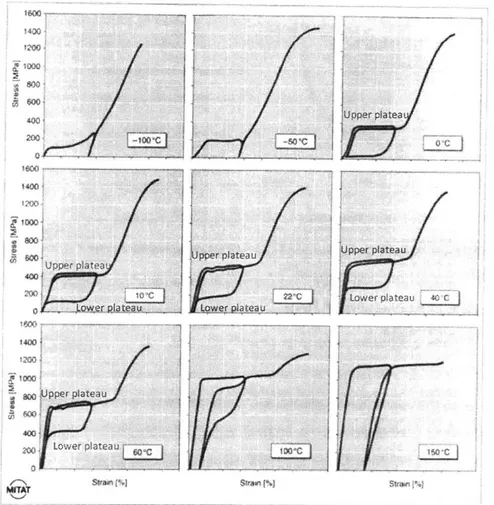
temperature (denoted in a box in each graph) around the Nitinol component affects the mechanical performance. Samples below 0 'C are clearly in the martensite state and do not exhibit superelasticity. Above 0 'C, the material shows evidence of superelasticity (austenite starts to form in this material at -22 C) with an upper plateau showing a transformation from austenite to martensite and a reverse transformation along the lower plateau upon unloading, returning the material back to near zero strain. The stress at which the upper and lower plateaus occur is often a design criterion for applications, which further constricts what the austenite finish temperature of the Nitinol alloy needs to be. Generally, Nitinol alloys engineered for medical device applications have austenite finish temperatures around 10-40 'C below body temperature to be in the superelastic state.
The transformation properties of Nitinol can be characterized by cycling temperature and measuring the heat released/consumed during the transformation between martensite and austenite, using a method known as differential scanning calorimetry (DSC). Figure 3, also derived from a review article by A.R. Pelton and coworkers [10] shows the output of a typical DSC experiment where key transformation properties such as the austenite finish temperature can be measured for a Nitinol component. The peak from heating (downward facing peak) is the transformation from martensite to austenite, with the material fully in the austenite phase after the peak (describes the austenite finish temperature). Other transformation temperatures play a
role on the mechanical properties of Nitinol as well, but are outside of the scope of this
work.
Upper a ea '400~00I
200 400 1000J
40& 0 low LwV r pjgqe ;400 !2w0 p L verplaeau 0 anea1%Figure 2. Stress-strain curves showing the mechanical performance of Nitinol with an austenite finish temperature 11 0C tested at different operating/ambient temepratures
(reproduced with permissionfrom A.R. Pelton et. al. [10]).
II
UJpper
pateau
Upper plateau LJ Low er p ateau...
...
...
-
....
3. A typical
03
-20
f\100 -50 0 50 10
MIAT Tewinafur 1'CJ
DSC curve (reproduced with permission from A.R. Pelton et. al.
1.1.2 Current Manufacturing Methods for Nitinol
The superelastic properties of Nitinol are critical to its use over other, more
traditional alloys such as steels. As mentioned in the previous section, the ability to
elastically deploy parts through hollow wires allows for much less invasive surgeries for
both short-term and long-term implantable devices [8,9]. Several other benefits of
superelasticity are subtler, such as kink resistance and biomechanical compatibility,
which lead to Nitinol being chosen for stents and guidewires for catheters as more
reliable alternatives to other alloys [9]. Shape memory properties are also utilized in
certain applications where the application of heat can change the shape of the material
without requiring invasive surgeries. Examples of shape memory Nitinol include wires in
orthodontics and bone plates for fractures [8,9]. A few applications use Nitinol directly in
the martensitic state for its ductility, such as the Paragon stent [8].
Manufactured wrought NiTi components for medical devices must meet the
American Society for Testing and Materials (ASTM) standards, ASTM F2063, for this
material [11]. The standard specifies that the nominal Ni composition must be between
54.5 and 57 wt.%. The Ni composition has a strong effect on the austenite finish
temperature [12], with increasing Ni composition leading to a lower austenite finish
temperature. Ni compositions in the range specified are expected to yield superelasticity
at body temperatures. In addition, the standards specify maximum compositions for
Figure
several impurity elements that can be introduced during the manufacturing and materials
processing stages. Table 1 shows the limits for these different impurities [11].
Table 1. Impurity element maximum allowances in Nitinol medical devices [I].
Maximum weight percentage
Carbon
0.05
Coba It
0.05
Copper
0.01
Chromium
0.01
Hydrogen
0.005
Iron
0.05
Niobium
0.025
Nitrogen + Oxygen
0.05
The presence of impurities can embrittle Nitinol alloys, leading to premature failure of
the component. Of particular importance, given the traditional manufacturing and
processing routes as well as expected exposure in the additive manufacturing process, are
the carbon, hydrogen, nitrogen, and oxygen contents. Minimizing the introduction of
these elements is an important part of designing the processes for producing Nitinol
components.
The conventional manufacturing processes for Nitinol are shown in Figure 4,
which is derived from a review article by Elahinia et. al [13]. Ni and Ti are typically
alloyed either through a melting and casting process or through powder metallurgy
(special processes include processes such as thin films produced by sputtering). Melting
requires a vacuum furnace as Ti is a highly reactive element, with vacuum induction
melting and vacuum consumable arc melting being the most widely used processes [14].
Both processes have been tuned by controlling the choice of crucible to minimize
impurities, the temperature of melting, and the rate of temperature change in casting
(usually very slow rates) to produce homogeneous parts with tight control over chemistry
Heat Treatment I -- --+ Hot Working
Cold Working
4
Heat Treatment 2-- Melting and Casting Cutting, Matching, Forming] Shape Memory Treatment
Special Processes
Casting, Finishing --- + NiTi product
Pure Ni and Ti
-Debinding, Sintering ---...- Heat Treatment Conventional Shape Memory Treatment PowderSpecial Processes
Casting. Finishing ----. - -. +.NiTi product
Special Processes... --- --- -- ---- - NiTi product
Figure 4. Conventional processing of Nitinol (reproduced with permission from Elahinia
et. al. [13]).
The subsequent steps in the process after melting and casting shown in Figure 4 generally aim to affect the microstructure, surface properties and final shape of the Nitinol component. Nitinol is generally first produced into thin wires or tubes from which the resultant part is produced. These steps are generally labor intensive and require delicate engineering to maintain the mechanical properties and superelasticity. Nitinol is a particularly difficult alloy to machine which limits the types of methods that can be used to create the desired shape.
Conventional powder route processing for Nitinol includes sintering (including spark plasma sintering and hot isostatic pressing) and metal injection molding and aims to make components near the desired net shape to reduce the number of manufacturing steps required to produce the final component [15]. Powder is produced generally using gas atomization in order to attain nearly spherical powder particles. Powder generally contains a higher impurity concentration than cast Nitinol ingots due to the higher surface area of the powder, which makes it difficult to control against the formation of oxide and carbide phases that embrittle the alloy [16]. Sintering and metal injection molding can
have high porosity due to the difficulty in fully consolidating the powder [17, 18], which
Nitinol applications, the presence of pores is another source of embrittlement and can lead to premature failure of the component.
The challenges associated with conventional Nitinol production are instructive to the efforts to produce Nitinol through additive manufacturing. The additive manufacturing technique that is primarily studied for Nitinol is selective laser sintering, which melts together Nitinol powder particles using a laser beam in an argon atmosphere. Ultimately the tantalizing potential of additive manufacturing for Nitinol is to produce parts near net shape to eliminate the costly manufacturing steps for current Nitinol parts and open up the potential for new geometries of Nitinol components. However, the challenges of using powder, which can have higher impurity concentrations and lead to porosity, and relying on a melting and solidification process through the laser which can affect the chemical composition and homogeneity of the part are major components of determining whether additive manufacturing of Nitinol is a viable technology.
1.2. Review ofAdditive Manufacturing Studies of Nitinol
Additive manufacturing of Nitinol has been studied by materials science researchers over the past 10 years to develop an understanding how the printing process affects the material properties and solve early challenges in creating high quality Nitinol through 3D printing. The most common additive manufacturing technique that is utilized for Nitinol is called selective laser sintering. Selective laser sintering uses a feed of metal powder, in this case Nitinol powder, which is sintered (effectively melted together) by a laser beam. A schematic of the process of selective laser sintering is shown in Figure 5
[15].
The process of selective laser sintering starts with a clean substrate on the "fabrication piston" side of Figure 5. A layer of powder is spread across the substrate by inching up the powder delivery piston and spreading the powder over the powder bed/substrate using a roller or other spreading device. The laser then selectively strikes the powder bed based on the uploaded CAD drawings of the desired part geometry. Key parameters of this process include the laser power (usually limited to a range based on the particular laser equipped on the machine) as well as the speed of the laser and the thickness of the powder layer that is spread across the bed. After the laser is finished with
one layer, the fabrication piston moves down by the specified powder layer thickness parameter and the next layer of powder is brought across by the roller. This process is repeated until the final part is finished.
LAser Scanner
System
Roller Powder Bed
Powder Delivery Fabrication
Piston Piston
Figure 5. A schematic of the selective laser sintering process, reproduced with permission
from
Elahinia et. al. [15].Components built from selective laser sintering have rough surfaces, which generally require surface finishing in post-processing (e.g. wet-blasting or tumbling). In addition, the components are adhered to a substrate and must be removed. Removal from the substrate depends on the part and can be done manually or require the use of an electrical discharge machining wire (EDM wire), which leaves a smooth finish.
While several companies supply selective laser sintering machines [4] with built-in parameter sets for common materials such as copper, titanium, steel, alumbuilt-inum alloys, etc., developing suitable process parameters for a new material still requires substantial tuning. In addition to the aforementioned laser power and speed parameters, much of the art of 3D printing with selective laser sintering is determining the pattern in which the laser rasters across a layer of the part and interprets the CAD file into a physical laser scanning strategy. The laser scanning strategy (a sample of different common ones are shown in Figure 6 which is derived from the work of Cheng et. al. [19]), for example, determines in what order the different areas of a part in a given layer are melted. The order in which parts are melted effects the thermal history that the material experiences
and can effect microstructural features (such as grain size), internal stresses (which cause
warping) from heating and cooling unevenly, and the pickup of impurities. Within each
strategy, the distance between consecutive laser passes in the same area is known as the
hatch spacing (i.e. the distance between lines in Figure 6), which also has a strong effect
on the thermal history and ultimate performance of the printed components.
Lx
Island scanning 45* rotate scanning Line scanning 900 rotate scanning 45* line scanning 67* rotate scanningIn-out scanning Out-in scanning
Figure 6. Laser scanning strategies for the body of selective laser sintering components, which can effect internal stresses, surface finish and the presence of porosity in the part
(reproduced with permission
from
Cheng. et. al [19]).In addition, scanning strategies for the surface layer of the part often differ, referred to as contour scans, which often have unique laser parameters to attain better surface finish and dimensional tolerance. Similarly, the first few layers binding the part to the substrate can
have different strategies to make the removal of the component after printing easier or to ensure rigidity during the printing process.
Selective laser sintering is well suited for a wide range of material components, from plastics to metals and ceramics, which has led to it being the prime method for exploring Nitinol 3D printing [20-44]. Other methods such as directed energy deposition that are flow based have also been explored [4548], but are not considered in this work. The remainder of this section highlights the findings of several research groups that have studied 3D printing of Nitinol using selective laser sintering [20-44].
The first key attributes of Nitinol that are generally necessary (i.e. regardless of particular application) is to be able to print components with sufficient density and chemical control, as these material properties are required for ductile, superelastic, and shape memory parts. Figure 7 is a summary of laser power and scan speed parameters for selective laser sintering that have been studied [20-44].
1500
Vig
power
E
E
E 1000
-vq_
0)
C00
100
200
300
Laser Power (W)
Figure 7. A summary of laser power and scan speeds used for selective laser sintering of
Nitinol, with two distinct regimes emerging: a low power regime with powers between 40-100 W and a high power regime with powers over 200 W [20-44].
The printing parameters fall into two regimes. Most studies have been conducted in the
40-100 W regime of power with correspondingly low scan speeds. This power range
reflects the operating power range of most commercial selective laser sintering machines.
A select few studies have been conducted at very high powers of 250 W using specialized
selective laser sintering equipment. Dadbakhsh and coworkers [42] summarized the
different output properties from printing parameters in these different ranges. In both
regimes high relative density components of greater than 99% were found (a high relative
density means that the material has few pores or voids). In addition, they found that lower
scan speeds generally lead to higher transformation temperatures, which naturally lends
these parts to be more useful for shape memory applications than superelastic
applications.
This effect of the printing parameters on the transformation temperatures, most
critically the austenite finish temperature, is critical to the viability of Nitinol additive
manufacturing. In earlier work, Dadbakhsh and coworkers studied this effect using high
power laser parameters and low power laser parameters, resulting in the DSC curves
shown in Figure 8 [40].
As-Printed With Annealing
M-A P 1.0. 1.0. O 4 M-A A 4 A 0.2 -. P 0.2 HP S0.0 0.0 -0.2 -0-2 08 -- 1
---04 1-A _Powd -4A0.4 MAPwe
-0.6 -0.6
-0.8 -0.8 MA
-1.0 -10
-100 -50 0 5D 100 ISO -100 -50 0 50 100 150
Temperature (C) Temperature (C)
Figure 8. DSC curves for selective laser sintered parts under low (40 W) and high power
(250 W) laser settings (reproduced with permission from Dadbakhsh et. al. [40]).
The DSC curves for the as-printed and virgin powder (on the left in Figure 8)
show a marked shift of the transformation peaks to higher temperatures at low power
printing parameters. The austenite finish temperature reaches around 80 'C from a virgin
-1
powder with an austenite finish temperature closer to 20 'C, which would be appropriate for superelastic Nitinol products at body temperature. Upon annealing the powder and the printed parts at 830 C for 25 minutes, the authors note that the low power curve is no longer shifted relative to the powder's DSC curve. Trends similar to this are observed in several studies of Nitinol selective laser sintering.
Based on these results, Dadbakhsh and coworkers identify several possible reasons for the increase in the transformation temperatures when printing the component at low power:
1) Preferential evaporation of Ni during printing due to the higher vapor pressure of
Ni which would lower the Ni content of the printed part and lead to a higher austenite finish temperature.
2) Precipitation of secondary phases of Ni, such as Ni4Ti3, which would decrease the
Ni content in the rest of the part and also lead to internal stresses and barriers to the phase transformation.
3) Smaller grains due to the different cooling rate which can affect the transformation
temperatures, and
4) Residual stresses and grain textures which can affect the transformation temperatures.
In their work, Dadbakhsh and coworkers claim that precipitation is the most likely cause for the increase in the transformation temperature as evidenced by the lack of differences in the transformation temperatures in the annealed structures. However, the root cause differs between different authors who have studied the increase in transformation temperatures. Bormann et. al. and Haberland and coworkers instead attribute the change in transformation temperatures to a loss in Ni content [23, 49], but do not present corroborating data measuring the loss of Ni to correlate with the observed increase in the transformation temperatures.
One of the main goals of this work is to understand whether Nitinol can be printed on commercial selective laser sintering machines, which means printing at less than 200 W, with superelasticity at body temperature. As part of this goal, the experiments should shed further light into the root cause for the increase in transformation temperatures that have been observed by others (Section 3.4.4).
. Oxygen 0 Ntrogen 715 A Carbon 0.10 0 0 200 400 600 800 Energy densiy o v (J.rnW)
Figure 9. Effect of printing parameters on the pickup of impurities in the printed parts (reproduced with permission
from
Haberland et. al. [23]).Another important factor that has been studied is the introduction of impurities during the printing process. During the laser sintering process, the material reaches its melting temperature and is susceptible to dissolve impurity species from the surrounding atmosphere or from the substrate. The atmosphere used is an argon atmosphere, but still contains oxygen and nitrogen in enough content to be introduced into the melt pool. Figure 9 from a study by Haberland et. al. [23] shows how the pickup of air elements in the argon atmosphere - oxygen and nitrogen - increase with the amount of energy introduced by the laser into the melt pool (energy is calculated based on the power of the laser and how long it sits over a particular area of the material). Using different methods to cycle the argon gas in printing chamber, Haberland et. al. [23] show that the increase in oxygen and nitrogen- content can be minimized to be in line with conventional Nitinol ingots. In this thesis, the impurity contents of printed Nitinol will also be a subject of study in determining whether parts can be consistently made to meet the ASTM F2063 standards for impurity content using commercial Nitinol powder as feedstock.
2. Thesis Outline
The ability to 3D print Nitinol components offers a new manufacturing route that can reduce costs for printing medical devices with complex geometries and opens up the opportunity for entirely new medical devices that could not previously be fabricated. As outlined in the Section 1.2, early research has been conducted by materials scientists to determine whether Nitinol can be fabricated using selective laser sintering in a lab setting. The research highlighted optimism in the ability to produce dense components and identified concerns regarding impurity content and an increase in the transformation temperatures of Nitinol.
This thesis begins by building on the academic studies exploring this technology to assess the feasibility of printing Nitinol components of medical grade in an industrial setting. The engineering assessment (Section 3) identifies the main performance metrics required in Nitinol medical device components, produces experimental results to determine whether these performance metrics can be met using selective laser sintering, and reveals the main challenges that remain for adoption of this technology in the medical device industry.
The engineering assessment is then used to explore the business case for 3D printed Nitinol for medical devices. The relative difficulty of achieving different engineering properties is used to identify the most likely applications for using this technology in the near future. A cost accounting model is developed for Nitinol to understand the operational and financial aspects of investing in Nitinol 3D printing and to identify the different costs associated with different routes of implementing this technology. This model is used to identify the general sizes and types of components that are most likely to experience large cost advantages over traditional Nitinol manufacturing.
This work was done with Boston Scientific, a leading medical device producer, headquartered in Maple Grove, MN. The work was primarily completed in Clonmel, Ireland.
3. Assessing Feasibility of Producing Quality Nitinol Components 3.1 Developing design targets for 3D printed Nitinol
Table 2 shows a summary of the main engineering properties that are considered in evaluating the quality of 3D printed Nitinol components. The stakeholders for this project include product development engineers, research and development scientists, and regulatory agencies (using the standards described in ASTM F2063 for Nitinol medical device components [11]). The majority of the properties that need to be met are mechanical properties, as it is the mechanical properties of Nitinol that make it a useful candidate for medical devices. In particular, the yield strength, % elongation at failure, % plastic strain after recovery, and # of cycles to failure were identified as critical properties
for which to meet specifications for a broad range of medical device applications.
Table 2. Engineering properties of Nitinol that should petformance ofprinted components
Property Type of Property Yield strenuth Mechanical
% elongation to fracture Mechanical
% plastic strain after recovery Mechanical
Upper plateau strength Mechanical
Lower plateau strength Mechanical
Ultimate tensile strength Mechanical
Young's modulus Mechanical
Shape memory effect extent Mechanical
# of cycles to failure Mechanical - Fatigue
Dimensional tolerances Geometrical
Corrosion resistance Chemical
Biocompatibility Chemical
be considered in evaluating the
Importance to Stakeholders High High High Moderate Moderate Low Low Low High High High High
The yield strength describes the maximum stress that the component can experience before it is permanently deformed (also known as plastic deformation). Plastic deformation is an important failure criterion for medical device components as once the
part is permanently deformed it will no longer perform its function in the manner in which it was designed. The % elongation to fracture describes the maximum strain that the material can experience before breaking. In the context of Nitinol this property is important mostly as it reflects the type of failure mode that occurs in these components. A % elongation that is too low can mean that the part is susceptible to undergo brittle fracture, as opposed to ductile fracture which allows for plastic deformation before failure and is generally required for medical device applications. The % elongation under elastic strain is also very important in Nitinol as it relates to its superelastic property. This property is captured in Table 2 as % plastic strain after recovery, which is the amount of permanent deformation that occurs in the component after the part has been deformed to a fixed strain and released. The fixed strain for deformation can vary based on the application, but is often set at 6% elongation for consistency across tests. For applications where fatigue plays an important role - which can broadly be described as any component that is used as a long-term implant - the # of strain cycles that the component can endure before failure is critical as it determines how long the component can remain in the body before fracture. The fatigue life of traditionally manufactured Nitinol is often cited as one of the most challenging engineering properties to achieve and is thus also likely to be one of the main challenges for 3D printed Nitinol [43], as 3D printing as a manufacturing technique is generally poor at achieving good fatigue properties.
In addition to mechanical properties, the dimensional tolerances of the components are critical to meeting the engineering requirements of Nitinol applications, which utilize fine features as is typical in the medical device industry (many critical feature sizes will be IOs to I00s of microns and each critical feature must be inspected to meet regulatory standards). Biocompatability is also an important consideration as Ni is toxic, and so careful design of the surface treatment of the part is required to ensure no Ni diffusion into the body.
The experiments in Section 3.4 are designed to identify the relative difficulty of achieving the different properties in Table 2.
3.2
Identifying
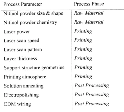
key tunable process parameters in the additive processThe properties of the printed Nitinol components will depend strongly on the process parameters used to 3D print Nitinol parts. Table 3 shows the most significant process parameters in the selective laser sintering process.
Table 3. Process parameters in the selective to achieve high peiformance Nitinol parts.
Process Parameter
Nitinol powder size & shape
Nitinol powder chemistry Laser power
Laser scan speed Laser scan pattern
Layer thickness
Support structure geometries Printing atmosphere
Solution annealing Electropolishing
EDM wiring
laser sintering process that need to be tuned
Process Phase Raw Material Ra-w Material Printing Printing Printing Printing Printing Printing Post Processing Post Processing Post Processing
The Nitinol powder is a critical input into the selective laser sintering process. The properties of the Nitinol powder depend strongly on the properties of the original wire that is used in gas atomization, particularly the chemistry, which includes the concentrations of Ni and Ti as well as the presence of impurities such as oxygen, nitrogen, carbon, and hydrogen which can have a very strong affect on the properties of the 3D printed component. While the powder properties are very important, as a medical device producer, testing various powders in a rapid manner is challenging as Nitinol powder is a relatively scarce resource with very few suppliers. Nitinol powder lead times are generally between 3 to 6 months.
Within the selective laser sintering process, several machine parameters can be tuned to perform a design of experiment to optimize around the desired properties. The
most common parameters that are used are the laser power, laser speed, and the laser scan strategy, which is often simplified to specify the distance between laser scans (called the hatch spacing). The amount of powder that flows onto the bed between recoats is determined by the layer thickness. In addition, the actual quality of the printing atmosphere can be particularly important for Nitinol where lower oxygen content is required (the ASTM F2063 specification for oxygen content is 0.05 wt%).
After printing, various post-processing techniques can be used to bring properties in line with the desired specifications. Solution annealing has been shown in several studies of 3D printed Nitinol [23,31,33,40] to help provide better superelastic properties. Solution annealing is performed by raising the temperature of the part up to an elevated temperature where various Ni,Ti compounds will dissolve and grains often will recrystallize to yield a more preferred grain structure. Subsequent annealing has also been shown to be useful to produce some desired precipitates [23,31].
The surface finish for traditionally manufactured Nitinol components is often provided by electropolishing and is thus an important potential step in producing high quality 3D printed Nitinol as well. For all parts, the printed component needs to be removed from the substrate, which is often done using an EDM wire, which can create localized heating on the cut surface.
Several of these parameters are studied in Section 3.4 to determine the most critical processing parameters for producing quality Nitinol components and to characterize the highest quality components produced.
3.3.
Identifying findamental
material properties that link processing parameters to desired properties for Nitinol produced by selective laser sinteringWhile Table 2 provides the properties of Nitinol that directly relate to the performance of the printed alloy, there are important material properties of Nitinol components that, while indirectly affecting the mechanical and functional properties of the alloy, are more direct consequences of the manufacturing process. In metallurgy, these relationships are called Process-Structure-Property relationships [50], where the process parameters in a manufacturing process directly affect the material at a structural level, and it is these material properties that directly cause the mechanical and functional
properties of the part. Figure 10 shows the Process-Structure-Property relationships for selective laser sintering of Nitinol.
Manufacturing Process
Process to create the final part from raw material. Includes:
* Process parameters of 3D printing
" Raw material properties * Post processing
Selective laser sintering of Nitinol
requires an understanding of how the Material Characteristics
process affects the desired properties. Material features which ultimately
This often requires first understanding effect performance. Includes:
how the process affects material 9 Porosity analysis
characteristics for a complex alloy such -Chemical characteristics
as Nitinol and how that material -Microstructure analysis
structure leads to the desired properties
Desired Properties
Engineering specifications for final part. Includes:
" Mechanical properties * Dimensional tolerances
-Surfacefinish
Figure 10. Schematic of engineering feasibility analysis of producing Nitinol using selective laser sintering
The important role that these structural features, or material characteristics in Figure 10, play in understanding the feasibility of producing engineering quality Nitinol through selective laser sintering can be understood by looking at the characteristics listed
Table 4.
Table 4. Material characteristics of Nitinol that can help understand how the 3D printing process affects the engineering properties of 3D printed Nitinol
Material Property Relative density Max pore size Surface quality
Impurity concentration Max inclusion size Grain size
Precipitated phase chemistry
Ni to Ti ratio
Transformation temperature
Strongly related engineering properties
00 elongation to
failure,
# cycles tofailure
% elongation to
failure,
# cycles tofailure
% elongation to
failure,
dimensional tolerance% elongation to failure, # cycles to
failure
% elongation to
failure,
upper/lower plateau Yield strength, upper/lower plateau, % recovery upper/lower plateau, yield strength, % recoveryUpper/lower plateau, % recovery
Upper/lower plateau, % recovery, (also depends on other material properties strongly)
The first two properties are relative density and maximum pore size, which both speak to the presence of defects in printed components. The presence of defects in the printed component is known to depend strongly on several processing parameters in Table 3. For example, if the laser power during the printing process is too low, the powder will not melt sufficiently leading to cavities in the part where the melted powder does not flow to fill. The presence of pores then directly affects mechanical properties. Substantial porosity in a component can lead to brittle fracture of the part, since the pore can be a natural place for cracks to initiate and propagate, which leads to a low %
elongation to fracture. To prevent brittle fracture, the part should have a high relative density (which speaks to the average porosity) and small pores overall.
The surface finish in particular is an important challenge in 3D printing as the components as-printed will have a surface roughness that will generally be outside of the specifications of the dimensional tolerances of parts. The tight dimensional tolerances can be difficult to meet when surface roughness causes significant variance in the dimension throughout the part. For Nitinol in particular the surface finish also must meet chemical requirements in order to assure biocompatibility of the parts and a high corrosion resistance. Ni is a toxic element and it is the oxide that forms on the surface of Nitinol that allows it to be used safely as an implant. A rough surface is also a fertile ground for
The impurity concentration in Nitinol is another important material characteristic for all Nitinol medical device components. Standards for Nitinol specify maximum concentrations of oxygen, carbon, hydrogen, and nitrogen among other impurities [11]. Each of these elements can play two roles that, like porosity, can lead to premature failure of the components through brittle fracture. Each of these impurity elements can form various compounds, or inclusions, for example titanium carbide (TiC) and titanium dioxide (TiO2), which are very hard phases formed within the part and form interfaces
that are highly susceptible to brittle fracture. These elements can also segregate to grain boundaries - interfaces between neighboring grains in the alloy - and weaken the bonding along that interface. This process is known as grain boundary embrittlement and these elements, particularly hydrogen, are potential embrittlers in Nitinol [51]. During the printing process, when powder is melted it reaches high temperatures where impurities have a much higher solubility in the metal. When the part is cooled, the components can retain higher concentrations of these elements which leads to the aforementioned issues.
A few processing parameters play a critical role in the impurity content of the
resulting components and the maximum size of any inclusions that form as a result. First, the raw powder itself should be as impurity free as possible, as impurity concentrations will only increase during the printing process. Secondly, the printing atmosphere, which in the commercial selective laser sintering machines considered here is typically an argon atmosphere, should have low impurity concentration and be circulated in the machine in a manner that minimizes exposure of impurity elements to the part [23]. Finally, the laser speed, power and scan strategy affect how long the part stays in the melted state and how fast it cools. A higher laser power and faster scan speed generally yield a lower concentration of impurities as the high laser power heats the material quickly and the fast laser speed moves the heat away from the part quickly allowing it to cool faster.
The grain size and the presence of any precipitated phases affect the yield strength of the part as well as the phase transformation that leads to superelasticity. The presence of smaller grains and many small precipitates can make the material harder - as the interfaces add strength to the material [52] - but can also make it harder for the material to transform. Precipitated phases in NiTi occur when regions of the material are off-stoichiometry and thus other stable phases can be formed as described in the Nitinol
phase diagram. These properties will be affected by the original chemistry of the powder as well as the printing parameters which affect the rate at which the material is heated and cooled.
The superelastic properties of Nitinol depend strongly on the concentrations of Ni and Ti in the NiTi phase [12], where increasing the amount of Ni can increase the temperature at which the phase transformation occurs significantly. The temperature at which martensite transforms to austenite is a critical material characteristic/functional property as superelasticity only occurs when the part is in the austenite phase (i.e. above the austenite temperature). For medical device applications, the material needs to be in the austenite phase at body temperature of 37 'C in order for superelasticity to occur. The difference between the phase transformation temperature and the temperature under which superelasticity is being tested determines where the upper and lower plateau stresses lie, which makes understanding where the transformation temperature occurs very important.
The transformation temperature is affected by the processing parameters in many ways. As mentioned, the relative concentrations of Ni and Ti affect the transformation temperatures. The presence of precipitated phases can preferentially consume Ni or Ti which changes their concentration in the NiTi phase. Ni has also been hypothesized to evaporate preferentially [23 49] to Ti during the selective laser sintering process, which again will depend on the the rate of heating and cooling. Transformation temperatures can also be dependent on residual stresses present in the 3D printed component which are common in 3D printed parts. These effects are discussed in more detail in Section 1.2.
Characterizing these material/structural properties is a critical step to understanding the challenges associated with selective laser sintering and is the fundamental driver behind the design of the experiments shown in Figure 12. The experiments focus primarily on the printing and post-processing parameters as opposed to the raw powder parameters, due to the aforementioned long lead times of sourcing multiple types of Nitinol powder. The experiments focus on addressing the mechanical properties in the most detail, as these properties are the most fundamental to the use of Nitinol in the medical device industry. To link these process parameters and mechanical
properties, parts will be characterized to study the level of porosity, surface roughness, transformation temperatures, and chemical concentrations.
Defect characterization
Relative density
* Max pore sizes
Process parameters Surface roughness Key mechanical properties
- Microstructure
Explore different: - High ductility
- Printing recipes Measure Design for - Superelasticity
- Post processing recipes I Shape memory effect - Transformation temps
- Impurity content
Ni to Ti ratio
Chemical characterization
Figure 12. Flow chart of the experimental assessment of the feasibility of 3D printing Nitinol components in Section 3.4.
3.4. Experimental analysis of the feasibility of 3D printing Nitinol using selective laser sintering
3.4.1. Methodology
Printing of Nitinol coupons was done on commercial selective laser sintering machines with the range of allowable laser powers ranging up to 100 W. Printing parameters were varied based on values provided in previous studies in the literature [20-44] (Figure 7). Using these values as initial seeds, further exploration was done using a basic square grid exploration of the printing parameter space. Post process annealing was conducted using a vacuum furnace, and annealing temperatures were determined based on the literature as well [20-44].
The porosity of components was measured mounting printed parts in an epoxy resin and polishing the samples to achieve a mirror finish. Polished samples were then analyzed using an optical microscope with 5x to 100x magnification. Surface roughness was measured by sending components to a scanning electron microscopy (SEM) service provider. Surface roughness of parts were studied before and after electropolishing, where electropolishing was also conducted through a service provider. Electropolishing

![Table 1. Impurity element maximum allowances in Nitinol medical devices [I].](https://thumb-eu.123doks.com/thumbv2/123doknet/14102925.465807/15.917.192.678.249.520/table-impurity-element-maximum-allowances-nitinol-medical-devices.webp)


![Figure 7. A summary of laser power and scan speeds used for selective laser sintering of Nitinol, with two distinct regimes emerging: a low power regime with powers between 40-100 W and a high power regime with powers over 200 W [20-44].](https://thumb-eu.123doks.com/thumbv2/123doknet/14102925.465807/20.917.198.591.552.888/figure-summary-selective-sintering-nitinol-distinct-regimes-emerging.webp)