Chapter 2. Basic Atomic Physics
Academic and Research Staff
Professor Daniel Kleppner, Professor David E. Pritchard, Dr. Wolfgang Ketterle, Dr. Alexander Martin
Visiting Scientists and Research Affiliates
Pin P. Chang,1 Dr. Theodore W. Ducas,2 Scott N. Paine,3 Dr. H. Joerg Schmiedmayer
Graduate Students
Michael P. Bradley, Kevin R. Boyce, Michael S. Chapman, Michael W. Courtney, Kendall B. Davis, Frank DiFilippo, Christopher R. Ekstrom, Troy D. Hammond, Jeffrey R. Holley, Hong Jiao, Michael A. Joffe, Robert P. Lutwak, Marc O. Mewes, Vasant Natarajan
Undergraduate Students
John E. Berberian, Tracie M. Drew, Matthew J. Marjanovic, J. David Pelly, Eliot J. Quataert, Alexis P. Silitch, Abraham D. Stroock, Bridget E. Tannian, John J. Wuu, Peter Yesley
Technical and Support Staff
Carol A. Costa
2.1 Millimeter-Wave Frequency
Measurement of the Rydberg Constant
Sponsors
Joint Services Electronics Program Contract DAAL03-92-C-0001 National Science Foundation
Grant PHY 89-19381
Project Staff
Pin P. Chang, Dr. Theodore W. Ducas, Jeffrey R. Holley, Robert P. Lutwak, Scott N. Paine, Professor Daniel Kleppner
The Rydberg constant, R., relates the wavelengths of the spectrum of atomic hydrogen to practical lab-oratory units. As such, R. is the natural unit for measurements of many atomic properties. Recent advances in optical wavelength metrology have enabled experiments using laser spectroscopy to measure R. with accuracy approaching 2 parts in
1011.4
While R. remains the most accurately measured fundamental constant, other high-precision exper-iments, which depend on R. as an auxiliary con-stant, demand even more accurate measurement. The accuracy of optical wavelength measurements is approaching the practical limitations of wave-length metrology. Further progress in the measure-ment of R. will require frequency measuremeasure-ments making use of the modern definition of length in terms of time intervals and the defined speed of light.
We are attempting to advance the measurement of R. by directly measuring cR., the "Rydberg fre-quency." By initially preparing highly excited "Rydberg" states of atomic hydrogen around n=30, we are able to measure millimeter-wave transitions to nearby states with the full precision of frequency metrology.
The goal of our experiment is three-fold: First is the reevaluation of R. itself, providing an inde-pendent check, in a different regime, on concurrent developments in optical wavelength metrology. Second is the measurement of the ground state
1 National Measurement Laboratory, Taiwan.
2 Physics Department, Wellesley College, Wellesley, Massachusetts.
3 Smithsonian Astrophysical Observatory, Cambridge, Massachusetts.
Chapter 2. Basic Atomic Physics
Lamb shift. Because our measurements involve high angular momentum states for which the Lamb shift is extremely small, our results may be com-pared with optical measurements of transitions between low-lying states to yield an improved measurement of the Lamb shift. Third is the fre-quency calibration of the spectrum of hydrogen, which may eventually lead to a single frequency standard extending from the radio-frequency regime to the ultraviolet.
Our experiment is performed with an atomic beam in order to suppress the Doppler effect and to avoid collisional perturbations. Atomic hydrogen is excited to a low angular momentum n=29, m=O state by two-photon stepwise absorption. The hydrogen atoms are then transferred to the longer lived n=29, m=28 "circular" state by the method of crossed electric and magnetic fields.5 The atoms enter a region of uniform fields in which the fre-quency of the resonant transition n=29, m=28
--n=30, m=29 is measured. The atoms interact with the millimeter-wave radiation at two locations in a Ramsey separated oscillatory fields geometry. The final state distribution of the atoms is measured by
a state-selective electric field ionization detector. The resonance signal is observed as a transfer of atoms from the n=29 state to the n=30 state as the millimeter-wave frequency is tuned across the tran-sition.
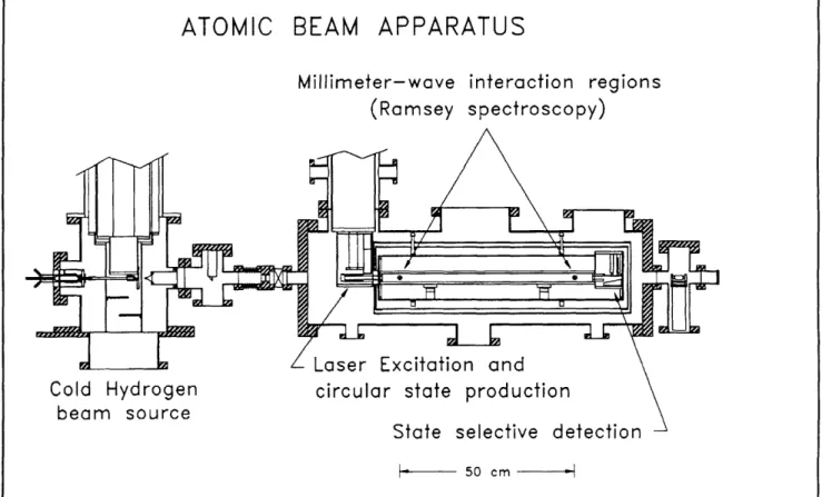
Figure 1 illustrates the main features of the appa-ratus. Atomic hydrogen or deuterium is produced by dissociation of H2 or D2 in a radio frequency dis-charge. The beam is cooled by collisions with the walls of a cryogenically cooled thermalizing channel in order to slow the beam and thereby increase the interaction time. The atoms are excited to the n=29, m=28 state by two-photon stepwise excitation in the circular state production region. The development of the hydrogen beam and optical systems was described in a previous Progress
Report. The magnetic field necessary to transfer
the atoms to the circular state is provided by per-manent magnets. The electric field is produced by an arrangement of strip electrodes which allows the direction of the field to be rotated. A detector in the circular state production region monitors the effi-ciency of the laser excitation and momentum transfer processes.
Figure 1. Schematic of the atomic beam apparatus.
After the atoms are prepared in the n=29 circular state, the beam enters the interaction region. Because Rydberg atoms interact strongly with external fields, accurate measurement of the energy level structure requires careful control of the inter-action environment. Thermal radiation is reduced by cooling the interaction region to -10 K by a liquid helium flow system. The ambient magnetic field is shielded out by a double-wall high-permeability shield. A small electric field, which defines the quantization axis of the atoms, is applied with high uniformity by field plates with cor-rective strip electrodes along the sides. The milli-meter waves intersect the atomic beam at two locations separated by 50 cm. The millimeter-wave optics were described in a previous Progress
Report.
The state distribution of the atoms emerging from the interaction region is analyzed by an electric field ionization detector. The atoms enter a region of increasing electric field produced by a ramped plate held at constant potential. The atoms in the n=30 state, which ionize at lower field, are collected in the first detector, while the n=29 atoms, which
ionize at higher field, are collected at the second detector.
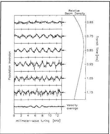
In the past year we have begun making measure-ments. Some typical time-resolved Ramsey fringe data is presented in figure 2. The accuracy with which we can currently extract R. from the data is limited by our understanding of the systematics of the experiment to about 1 part in 109. In order to extract all the necessary systematic information, it will be necessary to increase the signal-to-noise ratio of the experiment by a factor of at least 1000. Towards this end, efforts are underway to increase the duty cycle of the experiment and to decrease signal loss due to blackbody radiation. We have acquired a 120 Hz excimer pump laser to replace our aging 10 Hz YAG laser and have begun development of a new ultraviolet dye laser system. In addition to the improvement in signal from the increased repetition rate, we expect the new system to provide a narrower UV linewidth and, hence, improved efficiency of atomic excitation. We are also investigating alternative methods of circular state production which may lead to better radiation
Figure 2. Preliminary data displaying narrow linewidth
"Ramsey" fringes. The deuterium n=29, m=28 -- n=30, m=29 circular transition is shown. The time resolution of the detection system allows each velocity group to be studied independently. The velocity-averaged data is presented, along with the theoretical model, at the bottom of the page. Further refinement of these experiments will yield a measurement of R. with accuracy of 1 part in 1011.
shielding and simpler evaluation of the magnetic field strength in the interaction region.
2.1.1 Publications
Chang, P. Measurement of the Rydberg Frequency
Using Circular Rydberg States of Atomic Hydrogen. Ph.D. diss., Dept. of Physics, MIT,
1992.
Paine, S. High Precision Millimeter-Wave
Spectros-copy of Atomic Hydrogen. Ph.D. diss., Dept. of
Physics, MIT, 1992. 157 Reloative 0.65 0.75 -0. 0.85 2 - i . -i -g -C 0.95 0 . e! a tlo 1.15 0 2 4 6 8 10 12 m ilmeter-wove tu~ing [kHz] 3 01
Chapter 2. Basic Atomic Physics
2.2 The Diamagnetic Rydberg Atom
Sponsors
National Science Foundation
Grant PHY 89-19381
U.S. Navy - Office of Naval Research
Grant N00014-90-J-1322
Project Staff
Michael W. Courtney, Hong Jiao, Professor Daniel
Kleppner
A highly excited hydrogen atom in a strong
mag-netic field, the so-called "diamagmag-netic hydrogen
atom," is among the simplest nonseparable
systems in quantum mechanics.
Understanding
this atom could provide a key to the more general
aspects of nonseparable systems. The problem is
also attracting attention in the context of nonlinear
dynamics because its classical behavior displays a
transition from orderly to disorderly motion as the
energy is increased in a fixed magnetic field. One
can study the quantum structure of the system in
this regime both theoretically and experimentally.
Thus, the diamagnetic hydrogen atom provides an
ideal testing ground for studying the relation
between quantum structure and disorderly classical
motion, a subject sometimes called
"quantum
chaos."
We have developed techniques for carrying out
high resolution laser spectroscopy on the lithium
atom in a strong magnetic field. The difference
between lithium and hydrogen is minor for Rydberg
atoms.
The experiment uses a lithium atomic beam which
is excited by two c.w.
lasers.
The first laser excites
the atoms from the 2S state to the 3S state by a
two-photon transition and the second laser excites
the atoms to Rydberg states. The excited atoms
are detected by electric field ionization. We
typi-cally operate in magnetic fields near 6T. We can
determine the energy within 10-3
cm-1
, the
mag-netic field within 5 gauss.
Figure 3 shows the
atomic beam apparatus and superconducting
magnet.
The Hamiltonian for the diamagnetic hydrogen
atom, in atomic units, is
There are no general solutions to this problem and perturbation theory is inapplicable in the positive energy regime. In previous years, our experimental results6 have helped to stimulate theoretical advances, but an obsolete superconducing magnet made further progress difficult. The apparatus has been rebuilt using a new superconducting magnet. The new magnet employs a split coil configuration. The four-inch bore allows a significantly larger inter-action region and more convenient optical access than previously possible. Rydberg atoms are very sensitive to stray electric fields, which was a limiting factor in our previous work. Figure 4 shows the new interaction region in which stray electric fields are greatly reduced because surfaces are farther from the interaction volume. In addition, any stray electric field parallel to the magnet axis can be can-celled out by field plates, or an electric field can be applied as an addditional probe of the system. Another improvement in the interaction region is the collection of light from flourescence decay of the 3S state. One mirror focuses light onto a light pipe. Another doubles the area of collection by focusing light back to the point of interaction.
A scintillator and light pipe have replaced the surface barrier diode for detection of Rydberg atoms. After atoms are ionized, they are acceler-ated into the scintillator by a 15 KV potential. Light produced is carried to a photomultiplier by the light pipe. This detection method has the advantage of being able to count single ions. As a result, our signal is linear to the number of Rydberg atoms produced, and we detect nearly all the Rydberg atoms produced.
In certain regimes the system displays one-dimensional behavior. It is useful to write the
Ham-iltonian for the diamagnetic hydrogen atom as X= XP + z + h', where p 2 Sp= p2 1 LzB + B Pz2 1 Z1 2 Izl = 1 1 B + 1 B2 2 2 r 2 L 8
and J.C. Gay, Phys. Rev. Lett. 66:
Lett. 66: 145 (1991).
141 (1991); C. lu, G.R. Welch, M.M. Kash, D. Kleppner, D. Delande,
6 D. Delande, A. Bommier,
and
(, _ 1 1
jzj r
, is the Hamiltonian of an electron in a magnetic field, ),z is the Hamiltonian of one-dimensional Hydrogen, and Y ' is a perturbation to the other-wise trivial Hamiltonian. Although the perturbing potential is not small (in fact it is singular for the entire z=O plane), it has been shown7
that parts of the experimental spectrum can be understood simply in terms of the unperturbed Hamiltonian as a superposition of the spectra of one-dimensional Hydrogen and an electron in a magnetic field. Using the stray electric field in the old apparatus, we have studied the Stark splitting of the one-dimensional hydrogen atom that is approximated by magnetic confinement of the electron transverse to
the magnetic field. The measured field is in rea-sonable agreement with the splitting predicted by the one-dimensional model. However, it is more desirable to measure the Stark splitting at a variety of electric fields by using the electric field as a con-trolled probe to check how closely our system resembles one-dimensional Hydrogen. The new magnet and interaction region allow this to be done. Using a program written by Dominique Delande of E.N.S. Paris, we have calculated the spectra in many regions below the ionization limit. One result of these calculations suggests that there are energy levels which correspond to wavefunctions localized near the z=O plane. These levels can be con-nected with eigenvalues of a simple one dimen-sional model, and they produce the smallest anticrossings in the system. This suggests yet another undiscovered approximate symmetry. It also shows that in spite of the chaotic nature of the corresponding classical motion, the trivial periodic
Figure 3. Superconducting magnet and atomic beam apparatus.
7 C. lu, G.R. Welch, M.M. Kash, L. Hsu, and D. Kleppner, Phys. Rev. Lett. 63: 1133 (1989).
159
Chapter 2. Basic Atomic Physics
orbits in the z=O plane have a strong influence on the quantum spectrum. This has been shown pre-viously in the quasi-Landau modulations (periodic modulations in the oscillator strength of 1.5 times the cyclotron frequencys), but ours is the first work connecting these orbits with individual energy levels.
There is a growing interest in periodic orbit spec-troscopy. Periodic orbit spectroscopy is a tech-nique that relates the quantum mechanical spectrum to the periodic orbits of the corresponding classical system.9 Classically chaotic systems possess a proliferation of periodic orbits. The
clas-sical dynamics of diamagnetic hydrogen follow a simple scaling rule, and the Fourier transform of the constant-scaled-energy spectrum gives the scaled classical actions of periodic orbits. This has been shown experimentally,10 but many peaks in the Fourier transform were unresolved. A better tech-nique is needed to study quantum processes corre-sponding to classical bifurcations of periodic orbits. Classical bifurcation theory describes the manner in which new periodic orbits can be created out of old
ones or "out of nowhere" as the energy changes. We have shown that the results of Delande's program can be used to calculate the
constant-I
Figure 4. Interaction region.
8 J.C. Castro, M.L. Zimmerman, R.G. Hulet, and D.
Lett. 45: 1780 (1980).
Kleppner, "Origin and Structure of the Quasi-Landau Resonances," Phys. Rev.
9 A. Holle, J. Main, G. Wiebusch, H. Rottke, and K.H. Welge, "Quasi-Landau Spectrum of the Chaotic Diamagnetic Hydrogen Atom,"
Phys. Rev. Lett. 61: 161 (1988); J.-M. Mao and J.B. Delos, "Hamiltonian Bifurcation Theory of Closed Orbits in the Diamagnetic
Kepler Problem," Phys. Rev. A. 45: 1746 (1992).
10 A. Holle, J. Main, G. Wiebusch, H. Rottke, and K.H. Welge, "Quasi-Landau Spectrum of the Chaotic Diamagnetic Hydrogen Atom," Phys. Rev. Lett. 61: 161 (1988).
Atomic Beam
Mirrors
Field Plates
Plastic ScintilLator
Light Pipe
Laser Beams (into page)
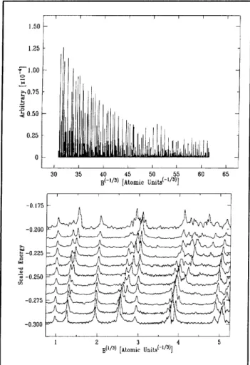
scaled-energy spectrum. One constant-scaled-energy spectrum and a series of Fourier transforms is shown in Figure 5. Each peak in the Fourier transform corresponds
of a periodic orbit. being compared with J.B. Delos.
to the scaled classical action These results are currently the semi-classical results of
1.50 1.25 1.00 S0.75 0.50 0.25 0 30 35 40 45 50 55 60 65
i-/) Atomic Units(-1/s)]
0.175 . -0.200 -0.225 -0.250 -0.275 -0.300 1 2 3 4 5 B( 1/ 3 ) [Atomic Units( -1/3)]
Figure 5. a) Constant-scaled-energy spectrum for a
scaled energy of -0.3. b) Fourier transforms. Each peak corresponds to a periodic orbit of the classical system.
2.3 Precision Mass Spectroscopy of
Ions
Sponsors
Joint Services Electronics Program Contract DAAL03-92-C-0001 National Science Foundation
Grant PHY 89-21769
Project Staff
Michael P. Bradley, Kevin R. Boyce, Frank DiFilippo, Tracie M. Drew, Matthew J. Marjanovic,
Vasant Natarajan, Abraham D. Stroock, Professor David E. Pritchard
In 1992, we undertook a program of measurement of the atomic masses of some key atoms important for the improvement of the nuclear mass table. Through major improvements in our experiment, we have increased our precision by a factor of 5 to less than 10-10 and performed several checks on our sources of error. This capability will allow us to do a variety of experiments in both fundamental and applied physics, including:
* The 3H+ - 3He+ mass difference, important in ongoing experiments to determine the electron neutrino rest mass;
* Determination of Avogadro's number NA, by weighing y-rays-and combined with the Rydberg, gives an independent value of a; Determing the Avogadro's number accurately would permit the replacement of the "artifact" mass standard by an atomic mass standard. * Improvement of many traditional applications of
mass spectroscopy by orders of magnitude improvement in both accuracy and sensitivity and,
* Determination of excitation and binding ener-gies of atomic and molecular ions by weighing the small decrease in energy, Am = EbinJc2 (we must reach our ultimate goal of a few * 10- 12 to
make this a generally useful technique).
Our experimental approach is to measure ion cyclotron resonance on a single molecular or atomic ion in a Penning trap, a highly uniform mag-netic field with axial confinement provided by weaker electric fields. We monitor the ion's oscil-lation along the magnetic field lines by detecting the currents induced in the trap electrodes. Working with only a single ion is essential because space charge from other ions leads to undesired fre-quency shifts. This work in trapping and precision resonance draws on techniques developed by Hans Dehmelt at the University of Washington and Norman Ramsey at Harvard University, for which they shared the Nobel Prize in 1989.
We have developed techniques for driving, cooling, and measuring the frequencies of all three normal modes of Penning trap motion. Thus, we can reproduce our manipulation of the ion position to within 30 microns of the center of the trap, cor-recting for electrostatic shifts in the cyclotron fre-quency to great accuracy. We use a 7r-pulse method to coherently swap the phase and action of
Chapter 2. Basic Atomic Physics
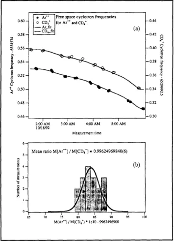
the cyclotron and axial modes." Therefore, although we detect only the axial motion directly, we can determine cyclotron frequency by meas-uring the phase accumulated in the cyclotron motion in a known time interval (figures 6a and 6b). In the past two years we have rebuilt our apparatus with a new Penning trap and quieter rf SQUID detector. We have implemented a new signal pro-cessing algorithm to improve our phase estimation by a factor of 2-3, resulting in a precision of 1 x 10⁻¹⁰ for a one-minute measurement. Our entire ion-making process has been automated, and the computer can cycle from an empty trap to having a cooled single ion in about 3 minutes. This has been partly due to a new broadband white noise generator that is used to expel unwanted ions.12
In addition, we have built an external ion source and associated optics that can produce and select ions with a resolution of 0.1. When this comes on line, we should be able to greatly reduce the percentage of "bad" ions and also alleviate the problem of residual neutral gas when using volatile species such as helium.
We have also developed a new measurement tech-nique that enables us to extend our precision com-parison to non-doublets of mass (actually mass to charge ratio). This has allowed us to perform strin-gent checks on systematics using such known ratios as N /N and Ar /Ar++. This represents a sig-nificant advance in precision mass spectrometry since it allows us to obtain absolute masses by direct comparison to carbon. Indeed, we have com-pared CD4 and CD5 to C to obtain two determi-nations of the absolute mass of deuterium. Mass ratios of doublets cannot be inverted to obtain absolute masses in general without comparing some species to carbon (C6H14/C7H2 to obtain H or C3D8/C4D2 to obtain D, for example). But we have
developed a scheme involving only doublet compar-isons that uses the known Ar+/Ar++ ratio to obtain the absolute masses of several light atoms-H, D, N, O, Ne, Ar-to about an order of magnitude better than the current standard mass table. The value of the deuterium mass obtained using this method is consistent with the value from the direct non-doublet comparisons, giving us confidence in our error estimates. With H and D thus known, we can obtain the mass of any ions by comparison with a suitable organic compound of the same nominal mass.
11 E.A. Cornell, R.M. Weisskoff, K.R. Boyce, and D.E. Pritchard,
Crossing," Phys. Rev. A 41: 312 (1990).
With the field imperfections (both magnetic and electric) shimmed as well as we can, our systematic errors are well below 5 x 10-". In one night of quiet magnetic time, we can get between 20 and 30 switches of the two ion species. The lowest statis-tical noise we have obtained thus far is 2.4 x 10⁻¹⁰
per shot (over the smooth drift in the field) and 6 x 10-11 for the night (see figure 6). We feel that this precision is perhaps the limit with the alternate ion scheme that we use now, but this is already quite a useful precision for the 3H - 3He and the NAh measurements described above. We plan to improve our precision either by shielding field
fluctu-Figure 6. (a) Cyclotron frequency as a function of time
for alternate CD, and Ar-+ ions in our Penning trap. The frequencies are obtained after a 50s integration of cyclotron phase (see text). The solid line is a polynomial fit to the drift in the field common to both ions. (b) A histogram of the individual ratios obtained between neighbouring points. Solid line is a gaussian distribution with a standard deviation of 2.4 x 10⁻¹⁰
"Mode Coupling in a Penning Trap: 7 and a Classical Avoided
ations better or having two ions in the trap at the same time.13
If we can get the shot to shot fluctuation below
1 x 10⁻¹⁰, the primary source of measurement noise will be the special relativistic mass shift due to thermal fluctuations in cyclotron amplitude. We have proposed a scheme of classical squeezing with parametric drives to reduce amplitude fluctu-ations.14 We hope to demonstrate its ability in reducing these fluctuations by a factor of 3 to 5. These techniques should help us in reaching our ultimate goal in precision of a few parts in 1012, necessary for weighing chemical bonds.
Publications
Boyce, K.R. Improved Single
nance Mass Spectroscopy.
Physics, MIT, 1992.
Ion Cyclotron
Reso-Ph.D. diss. Dept. of
Cornell, E.A., K.R. Boyce, D.L.K. Fygenson and D.E. Pritchard. Two Ions in a Penning Trap: Implications for Precision Mass Spectroscopy."
Phys. Rev. A 45: 3049-3059 (1992).
DiFilippo, F., V. Natarajan, K.R. Boyce, and D.E. Pritchard. "Classical Amplitude Squeezing for Precision Measurements." Phys. Rev. Lett. 68:
2859-2862 (1992).
2.4 Atom Interferometry
Project Staff
John E. Berberian, Michael S. Chapman, Christopher R. Ekstrom, Troy D. Hammond, Eliot J. Quataert, Dr. H. Joerg Schmiedmayer, Bridget E. Tannian, Professor David E. Pritchard
Sponsors
Joint Services Electronics Program
Contract DAAL03-92-C-0001
U.S. Army - Office of Scientific Research Contract DAAL03-89-K-0082
U.S. Navy - Office of Naval Research Grant N00014-89-J-1207
During 1992, we refined our atom interferometer5 and began performing experiments with spatially separated beams. The interferometer is now oper-ating with smaller period groper-atings,16 providing
greater beam separation. The experiments were performed with the aid of an interaction region that inserts a thin metal foil between the beams. This allowed us to manipulate the atomic wave function in only one arm of the interferometer.
Atom interferometers will make possible quali-tatively new types of experiments involving inertial effects, studies of atomic and molecular properties, and tests of fundamental physics. In addition, they may ultimately open the way for making ultra-small structures using atom holograms.
* The relatively large mass and low velocity of atoms make atom interferometers especially sensitive to inertial effects such as rotation, acceleration, and gravity. Sagnac rotation has been observed in accord with theoretical pre-dictions17 and sensitivity to gravitational accel-eration at the 3 x 10⁻⁶ level has been demonstrated.18 Atom interferometers may become the best absolute accelerometers and gravimeters in the next few years.
* Atom interferometers can be applied to a number of experiments in fundamental physics: tests of quantum mechanics such as the Aharonov-Casher effect,17 geometric phases and the measurement process, measurement of the equality of proton and electron charges, and a precise measurement of the momentum of a photon. This latter measurement should produce a new high precision value for the fun-damental constants NAh.
13 E.A. Cornell, K.R. Boyce, D.L.K. Fygenson and D.E. Pritchard, Two Ions in a Penning Trap: Implications for Precision Mass Spec-troscopy." Phys. Rev. A 45: 3049-3059 (1992).
14 F. DiFilippo, V. Natarajan, K.R.Boyce, and D.E. Pritchard, "Classical Amplitude Squeezing for Precision Measurements." Phys. Rev.
Lett. 68: 2859-2862 (1992).
15 D.W. Keith, C.R. Ekstrom, Q.A. Turchette, D.E. Pritchard, "An Atom Interferometry for Atoms," Phys. Rev. Lett. 66: 2693 (1991).
16 C.R. Ekstrom, D.W. Keith, and D.E. Pritchard, "Atom Optics Using Microfabricated Structures," Appl. Phys. B 54: 369 (1992).
17 F. Riehle, T. Kisters, A. Witte, J. Helmcke, and J. Borde, "Optical Ramsey Spectroscopy in a Rotating Frame: Sagnac Effect in a Matter Wave Interferometer," Phys. Rev. Lett. 67: 177 (1991).
18 M. Kasevich and S. Chu, "Atomic Interferometry Using Stimulated Raman Transitions, Phys. Rev. Lett. 67: 181 (1991).
Chapter 2. Basic Atomic Physics
Interferometers for atoms and molecules will offer more accurate ways to measure intrinsic properties of these particles, like their polariza-bility. They will also open up new areas of study, such as measurements of the "index of refraction" of a gas for a particle beam which passes through it.
The key component of our interferometer is the set of three matched transmission diffraction gratings which we constructed at the National Nanofabrica-tion Facility (NNF) at Cornell University. The process allows fabrication of precisely positioned openings in thin silicon nitride membranes mounted in silicon frames. The pattern created in the mem-brane is determined by an electron beam writer, making the process quite versatile. This process was used to create a variety of diffraction gratings used in the interferometer. In addition, several zone plates (atom lenses) were also built, and were later successfully demonstrated.19
Our present interferometer consists of three 200 nm period transmission gratings, mounted 0.66 m apart on separate translation stages inside the vacuum envelope. During operation, the 0th and 1st order
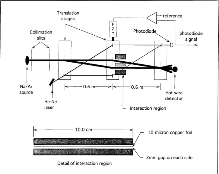
beams from the first grating strike the middle grating (which is 140 tm wide) where they are diffracted in the ls' and - 1st orders so that they converge at the third grating. At the second (middle) grating the beams have widths of 30 tm (FWHM) and are separated by 55 tm. The first two gratings form an interference pattern in the plane of the third grating, which acts as a mask to sample this pattern. The detector, located 0.30 m beyond the third grating, records the flux trans-mitted by the third grating. An interaction region, consisting of a stretched metal foil positioned sym-metrically between two side electrodes, is inserted in the interferometer so that the atom wave in the two sides of the interferometer went on opposite sides of the foil. The foil was 10 cm long and 10 microns thick and the gap between the foil and each electrode, where the separated atom beams traveled, was 2 mm. Figure 7 shows the design of the interferometer.
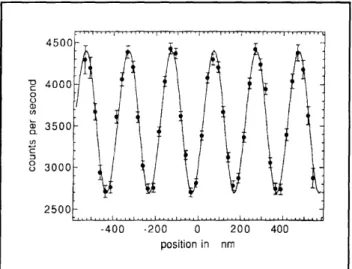
The data necessary to determine the interferometer phase and contrast are acquired by modulating the position of one grating relative to the other two and simultaneously recording the signal from the atom counting electronics as well as the signal from an optical interferometer used to measure the relative position of the gratings. After removing data obscured by noise spikes from the hot wire, the
atom count rate data are averaged into bins according to relative grating position, resulting in the fringe pattern shown in figure 8. The peak to
peak amplitude of our interference signal is 1600 Hz, which enables us to determine the interferom-eter phase to a precision of 15 milliradians in 1
minute.
By putting an electric field on one side of the inter-action region, the interference pattern is shifted. This phase shift is caused by the DC Stark shift of the atom. The Stark shift is -aE2/2 , where a is the electric polarizability and E is the electric field. The measured phase shift was quadratic with the applied field, allowing us to determine the polariza-bility of the ground state. Figure 9 shows the phase shifts versus applied electric field. By observing the reduction of the interference contrast with increasing phase shift, we can measure the longitudinal coherence length of the atomic beam. Our coherence length is 1.6 A, consistent with the measured velocity distribution.
In another experiment, we apply a uniform magnetic field along the beam axis to determine the quantiza-tion direcquantiza-tion. By running a current down the metal foil, perpendicular to the plane of the interferometer, we increase the field magnitude on one side of the interaction region (thus on one beam) and decrease it on the other. This gives a differential Zeeman energy, and therefore phase, for the two paths that is proportional to the septum current and the projection of the magnetic moment along the beam axis.
The interference pattern of each of the eight sodium ground states shifts independently. There are five different values of the angular momentum projection (one each mF ± 2, two each mF=-l,0). The dif-ferent interference patterns superpose to produce an interference pattern whose contrast depends on the differential Zeeman shifts. This is shown in figure 10. The first revival of contrast is the point where the phase shifts are: ±4T for the ImF = 2 states, ±2T for the ImF = 1 states, and 0 for the mF = 0 states.
The scientific future of atoms interferometers looks bright: atom beam sources are inexpensive and intense relative to other particle beams/sources (e.g., neutrons, electrons); several techniques have now been demonstrated to make interferometers for them; and the atoms which may be used in them come with a wide range of parameters such as polarizability, mass, and magnetic moment. This assures the applicability of these instruments to a
wide range of measurements of both fundamental and practical interest.
Publications
Berberian, J. Measuring the Isotropic Polarizability
of the Sodium Ground State. S.B. thesis, Dept.
of Physics, MIT, 1992. Ekstrom, "Atom Appl. C.R., Optics Phys. B
D.W. Keith, and D.E. Pritchard. Using Microfabricated Structures," 54: 369-374 (1992).
Turchette, Q.A., D.E. Pritchard, and D.W. Keith. Numerical Model of a Multiple Grating Interfer-ometer, J. Opt. Soc. Am. A 9: 1601-1606
(1992).
Pritchard, D.E. "Atom Interferometers." In Pro-ceedings of the 13th International Conference on Atomic Physics, Munich, Germany, August
3-7, 1992, Eds. T.W. Hansch and H. Walther.
Translation stages reference Collimation slits
I
Na/Ar source He-Ne laser < 1 0.0 cm Mak-M"10 micron copper foil
2mm gap on each side Detail of interaction region
photodiode signal
0.6
m 1I
Hot wire detector interaction regionFigure 7. A schematic, not to scale, of our atom interferometer showing the active vibration isolation system and the interaction region. The 10 [m copper foil is shown between the two arms of the interferometer (thick lines are atom beams). The optical interferometer (thin lines are He-Ne beams) is used for active vibration isolation. The 200-nm period atom gratings are indicated by a vertical dashed line, and the 3.3-km period optical gratings by a vertical solid line.
165
Chapter 2. Basic Atomic Physics 0 0 (D En 4500 4000 3500 3000 2500 -400 -200 0 200 400 position in nm
Figure 8. Interference pattern from 40 seconds of data. The interference signal is 860 counts per second with a contrast of 25%, which allows us to determine the phase to 15 milliradians in 1 minute. A background of 120 counts per second has been subtracted.
0 400 800 1200 1600 electric field in volts/cm
Figure 9. Stark phase shifts for voltages applied to the
right (open circles) and the left (filled circles) sides of the interaction region. Phase shift per applied electric field in (volt/cm)2 is 1.220(7) x 10-s for the left side and
1.224(7) x 10-5 for the right side. This measurement
sta-tistically determines the dc polarizability of sodium to 0.4%.
2.4.1 Cooling and Trapping Neutral Atoms
Sponsors
Joint Services Electronics Program Contract DAAL03-92-C-0001 U.S. Navy - Office of Naval Research
Grant N00014-90-J-1642 30- 25- 20- 15- 10-0O 0 200 400 600 septum current in mA 800 1000
Figure 10. Contrast revival from the independent precession of the 8 different internal ground states of sodium. A current flows down the septum, altering the size of an axial magnetic guide.
Project Staff
Dr. Alexander Martin, Dr. Wolfgang Ketterle, Kendall B. Davis, Michael A. Joffe, Marc O. Mewes, J. David Pelly, Alexis P. Silitch, John J. Wuu, Pro-fessor David E. Pritchard
Our current objective is to obtain samples of atoms at very high density and ultra-low temperatures. This goal is pursued by using a high flux slower for atoms, a dark light trap to stop and compress the atoms, and a magnetic trap for the final confine-ment and cooling.
Experiments with dense samples of cold neutral atoms promise exciting new discoveries in basic and applied physics. Due to the considerably reduced thermal motion of atoms, they are ideal for high resolution spectroscopy and for more accurate atomic frequency standards.
Collisions of ultra-cold atoms in such samples are characterized by a long deBroglie wave-length and are dominated by weak long-range interactions. Since the collision duration for slow atoms greatly exceeds the radiative decay time, stimulated and spontaneous radiative transitions can take place during the collision. Slow collisions are therefore radically different from fast collisions studied so far and will
become an exciting new field of atomic physics.20
High density samples of atoms open possibil-ities for observing quantum collective effects such as Bose-Einstein condensation and col-lectively enhanced or suppressed radiative decay.
In 1992, we completed work on an inverse Zeeman slower, which produced the highest flux of cold atoms obtained to date. We demonstrated that further enhancement is possible by transverse collimation of the slow atom beam inside the slower. The slow atoms were captured in a novel light trap, a "dark SPOT" (dark spontaneous force optical trap), which enabled us to confine more than
1010 atoms at densities one to two orders of
magni-tude higher than achieved to date. In addition, two theoretical papers were published on possibilities (and impossibilities) of trapping and cooling atoms by external fields.
Inverse Zeeman Slower
In a Zeeman slower the changing Doppler shift as an atom slows is compensated by the Zeeman shift in an inhomogeneous magnetic field. This method has the advantage of producing a continuous beam of slow atoms and has a practically unlimited velocity capture range. In the original implementa-tion of Zeeman slowing, however, one encountered difficulties in producing beams of atoms with veloci-ties lower than 200 m/s. The major problems were off-resonant slowing of atoms after they left the slower and substantial spreading of the slow atomic
beam due to transverse heating.
To solve the first problem we chose the recently demonstrated inverse Zeeman slower which slows atoms using a - light.2 1 This type of slower requires
a magnetic field increasing along the atom's trajec-tory until the atoms are slowed to the desired final velocity. The magnetic field drops off rapidly after reaching this maximum, thus quickly shifting atoms out of resonance and reducing off-resonant slowing (figure 11). The atomic densities in the slow beam were high enough so that the longitudinal velocity distributions could be determined directly from
Figure 11. Experimental setup for the inverse Zeeman slower: A beam of sodium atoms is slowed by counter-propagating laser light inside a solenoid with a parabolically increasing magnetic field. The slow atomic beam is collimated and deflected inside the slower by transverse two-dimensional optical molasses.
absorption spectra for the first time. This allowed the unambiguous measurement of absolute flux-values of 2 x 10¹¹ atoms/sec at 40 m/sec and
1012 atoms/sec at 100 m/sec through a 4 cm2 cross
section were obtained. The observed drop in flux for small velocities showed an approximate v2 dependence, consistent with spreading of the slow beam due to transverse heating during the slowing process.
The problem of transverse spreading of the slow atoms has been reduced by application of trans-verse cooling with red molasses. This was applied inside the slower, at the stationary field point where the atoms have essentially completed their slowing, but have not yet had time to spread transversely. The transverse velocities were reduced from - 2.5 m/s to - 1 m/s, resulting in a sixfold increase in the density of the slow atoms. Furthermore, deflection of the slow atomic beam by imbalancing the molasses beams resulted in complete separation of the slowed beam from both the original thermal beam and the slowing laser beam; this is important for experiments requiring slow atoms unperturbed
by laser beams or collisions with thermal atoms.
20 P.S. Julienne and J.Vigue, "Cold Collisions of Ground- and Excited-state Alkali-metal Atoms," Phys. Rev. A 44: 4464 (1991).
21 T.E. Barrett, S.W. Daport-Schwartz, M.D. Ray, and G.P. Lafyatis, "Slowing Atoms with a -Polarized Light," Phys. Rev. Lett. 67: 3483 (1991).
Chapter 2. Basic Atomic Physics
A Dark Light Trap for Neutral Atoms
The most common method of obtaining high density samples of cold atoms is to use a magneto-optical trap (MOT) to collect, cool and confine the atoms. However, the maximum density achieved in a MOT has been limited so far to - 1011 atoms/cm3 by two processes: (1) trap loss due to collisions between ground- and excited-state atoms,2 2 and (2) repulsive forces between the atoms caused by reabsorption of scattered photons (radiation trapping).23
We have demonstrated a dark SPontaneous-force Optical Trap ("dark SPOT"), in which all the above-mentioned limitations are mitigated by confining the atoms mainly in a ("dark") hyperfine ground state which does not interact with the trapping light. The key idea is "shelving" atoms, i.e., cooling and trap-ping forces are only exerted on the small fraction of atoms in the "bright" state. In such a trap, more than 1010 sodium atoms have been confined to den-sities approaching 1012 atoms cm-3 (figure 12). A similar number of atoms have been previously trapped by light forces only at densities 20 times lower.
The high densities achieved in a dark SPOT are promising for the observation of evaporative cooling after transferring the atoms into a magnetic trap. At densities of 1012 cm- 3, the estimated elastic colli-sion rate is already 100 s-1, much larger than the trap loss rate due to collisions with the background gas.
Trapping and Cooling Atoms by External
Fields
In a theoretical paper we have studied possibilities of using electric, magnetic and gravitational fields to trap atoms in the ground state. A trap for particles in the lowest internal state is highly desirable since loss by two-body collision is endothermic and thus suppressed. However, we were able to prove that it is impossible to trap ground state particles at rest using arbitrary combinations of electric, magnetic, and gravitational fields, a result which is a consider-able generalization of a previous theorem. Confine-ment of ground state particles is possible if they are in motion (dynamic equilibrium). Our analysis showed that axially symmetric storage rings with electric or magnetic fields are possible and should be experimentally feasible.
-100 -50 0 50 100
Frequency [MHz]
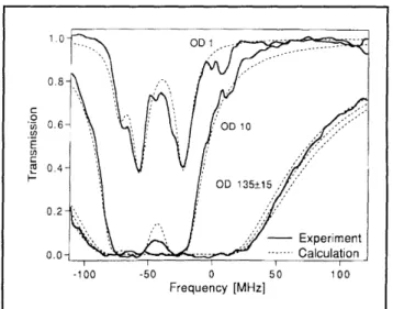
Figure 12. Absorption spectrum of a 4-mm diameter cloud of sodium atoms trapped in a dark SPOT. The best fit yields an optical density (OD) of 135 which corre-sponds to an atomic density of 7 x 1011 cm-2 and -5 x 10¹⁰ trapped atoms. Traces with lower OD were recorded with a reduced number of atoms. The dashed lines are calculated spectra for OD = 1, 10, 120, 135, and 150, respectively.
Recently, cooling schemes for atoms have been suggested which rely solely on time-dependent con-servative forces. We were able to devise a theorem showing that time-dependent potentials cannot increase the phase-space density of atoms, even if the motion is nonclassical. "Real cooling" or "brightening" of atoms is only possible if the time evolution in non-unitary, e.g., by spontaneous emis-sion of photons or loss of atoms (evaporative cooling).
Publications
Joffe, M.A., W. Ketterle, A. Martin, and D.E. Pritchard, "Transverse Cooling and Deflection of an Atomic Beam Inside a Zeeman Slower." Sub-mitted to J. Opt. Soc. Am. B
Ketterle, W., K.B. Davis, M.A. Joffe, A. Martin, and D.E. Pritchard, "High Densities of Cold Atoms in a Dark Spontaneous-force Optical Trap." Phys. Rev. Lett. 70: 2253 (1993).
Ketterle, W., A. Martin, M.A. Joffe, and D.E. Pritchard. "Slowing and Cooling Atoms in
22 M. Prentiss, A. Cable, J.E. Bjorkholm, S. Chu, E.L. Raab, and D.E. Pritchard, "Atomic-density-dependent Losses in an Optical Trap,"
Opt. Lett. 13: 452 (1988).
Isotropic Laser Light." Phys. Rev. Lett. 69:
2843-2846 (1992).
Ketterle, W., and D.E. Pritchard. "Atom Cooling by Time-dependent Potentials." Phys. Rev. A 46: 4051-4054 (1992).
Ketterle, W., and D.E. Pritchard. "Trapping and Focusing Ground State Atoms with Static Fields." Appl. Phys. B 54: 403-406 (1992). Pritchard, D.E., and W. Ketterle. "Atom Traps and
Atom Optics." In Lecture Notes of the Interna-tional School of Physics Enrico Fermi, Varenna,
1991.