Aligning Design and Development
Processes for Additive Manufacturing
By
Michael L. Stern
S.B. Mechanical Engineering
Massachusetts Institute of Technology, 2009
MASSACHU SETT WST TUTE
01 C.HNOLOLC3Y
JUL 3
0
2015
LIBRARIES
Submitted to the Department of Mechanical Engineering in
Partial Fulfillment of the Requirements for the Degree of
Master of Science in Mechanical Engineering
at the
Massachusetts Institute of Technology
June 2015
2015 Massachusetts Institute of Technology. All rights reserved
Signature redacted
Sign ature o f A uth or
...
-- - --- . .. ...
... .
Michael L. Stern
Department of Mechanical Engineering
May 21, 2015
Certified by ...
Signature redacted
Maria
Yang
Associate Professor of Mechanical Engineering
Thesis Supervisor
Accepted by...
Signature redacted
David E. Hardt
Professor of Mechanical Engineering
Chairman, Department Committee on Graduate Studies
Aligning Design and Development
Processes for Additive Manufacturing
By Michael Stern
Submitted to the Department of Mechanical Engineering on May 21, 2015 in Partial Fulfillment of the
Requirements for the Degree of Master of Science in Mechanical Engineering
Abstract:
Rapid Prototyping has transitioned from only being able to produce delicate
prototypes to being capable of producing robust production parts. As part of this transition, it has been renamed Additive Manufacturing (AM). As a true manufacturing technology, it has become important to deliberately design parts for Additive Manufacturing, and research has begun in how best to achieve this. This thesis explores the background of Additive Manufacturing, the growth in its use as a manufacturing technology, and the advantages and challenges of the technology. Following background information, this thesis progresses to different design approaches and technologies that promise to be effective when paired with AM. A design methodology using topology optimization is proposed, detailed and then tested on two case studies. The first case is a high-speed mirror for imaging and the second case is an aircraft bracket for the 2013 GrabCAD-GE design challenge. This thesis also includes an examination of the implementation of the proposed methodology on these case
studies and the resulting designs. The design from both case studies achieved a greater than
60% weight reduction through the use of design methodology tailored for AM.
The final section of the thesis shifts from the design process to the development process where the impact of AM is examined. In order to gain an understanding of the influence that Additive Manufacturing has on production, this thesis includes a synthesis of the literature from Additive Manufacturing as well as Design and Management. The benefits
are approached from an economic perspective, reviewing the first order benefits that have been extensively studied and then progressing to the second order benefits, and indirect benefits, which have not been examined in detail before. To understand the full effect of Additive Manufacturing on product development, the consideration of advantages such as high fidelity prototypes, decreased risk, faster time to market and late stage design flexibility are assessed.
Acknowledgments
I would like to thank those who were instrumental in my education. You have helped me reach the
MIT Graduate School of Mechanical Engineering, aided me in the pursuit of meaningful research and guided me in writing a coherent thesis.
Maria Yang, Lois Feldman, Fred Stern, Kaidyn Becker, Laura Brennan, Nathaniel Lubin, Jim Ingraham, Scott VanBroekhoven, Eli Niewood, Ken Estabrook and all of the students in the Ideation Lab.
Glossary
3-Matic-STL
3-Matic-STL is a software tool for directly editing STL meshes produced by Materialise.
Additive Manufacturing (AM)
American Society for Testing and Materials (ASTM) F42 definition: "a process of joining materials to make objects from 3D model data, usually layer upon layer, as
opposed to subtractive manufacturing methodologies [1]"
AlSi1OMg
AlSil 0Mg is an aluminum alloy used in metallic powder bed fusion it is 10% silicon and roughly 0.5% magnesium by weight.
CBush
CBush is a type spring element form the Nastrtran FEA system (used in Optistruct). They have independent coefficients of translational and rotational stiffness and join
two nodes to each other.
Computer Aided Design (CAD)
Computer Aided Design is a software tool that is used for creating 2D or 3D digital models.
Computer Based Design (CBD)
Computer Based Design is a term coined by Mistree and Muster that defines a category of design tool where the user does not directly model features but instead builds models generatively or with the assistance of the computer [2].
Design for Additive Manufacturing (DFAM)
Design for Additive Manufacturing is an area of study that examines how best to create parts and assemblies for Additive Manufacturing.
Design for Manufacturing and Assembly is a term coined by Boothroyd and
Dewhurst for a process focusing on the redesign of parts to maximize the efficiency of manufacturing and assembly.
ElectroOptical Systems (EOS)
Electro Optical Systems GmbH is a manufacturer of Additive Manufacturing powder bed fusion systems.
Fused Deposition Modeling (FDM)
Fused Deposition Modeling is a term coined by Stratasys LTD. for a plastic material extrusion process.
Meshmixer
Meshmixer is a software tool for directly editing STL meshes produced by Autodesk.
Optistruct
Optistruct is a finite element solver produced by the Altair company. It has the capability to run SIMP topology optimization.
OSS Smooth
OSS Smooth is a thresholding and smoothing tool. It is also capable of creating a
reanalysis model where the thresholded geometry is returned as a new finite element model with the original loading and boundary conditions applied to it.
Powder Bed Fusion (PBF)
An Additive Manufacturing process in which thermal energy selectively fuses regions of a powder bed.
Rapid Manufacturing (RM)
Rapid Manufacturing is "the use of a CAD-based automated Additive Manufacturing process to construct parts that are used directly as finished products or components [3]."
RBE 3
A RBE 3 is the type of rigid body element (used in Optistruct), created as part of the NASTRAN FEA system. It is often used to connect constraints to a set of elements.
It can be used in a wagon wheel configuration typically join elements of a circular feature to a central node, such as in a bolt constraint.
Selective Laser Melting (SLM)
Selective Laser Melting is a term for a powder bed fusion process typically applied to metallic processes.
Self-weighting
Self-weighting is a term describing the loading of optical components. It is the concept that the mass of an optical component drives its own inertial loading.
Solid Isotropic Material with Penalization (SIMP)
SIMP is a methodology for TO developed by Bendsoe and Kikuchi that utilizes element weightings and finite element analysis to optimize problems [4].
TI6AL4V
Ti6A14V is a titanium alloy with 6% aluminum and 4% vanadium by weight as alloying elements. It is commonly used in metallic powder bed fusion systems.
Topology Optimization (TO)
Topology optimization is an optimization method that redistributes material to create an optimized layout for a given objective while subject to a set of constraints. Most topology optimization solvers use the SIMP algorithm.
Unmanned Air Vehicle (UAV)
Table of Contents
Chapter 1: Background on A dditive M anufacturing... 16
1.1 Introduction:... 16
1.2 A dditive M anufacturing Term inology ... 16
1.2.1 Types of M anufacturing Processes... 16
1.2.2 Com puter-Controlled A dditive M anufacturing... 17
1.2.3 U se of A dditive M anufacturing ... 18
1.2.3.1 Four Categories of U tilization... 18
1.2.3.2 V isual M odels... 19
1.2.3.3 Fit-Check Prototypes ... 19
1.2.3.4 Fixtures and Patterns ... 20
1.2.3.5 End-U se Parts ... 20
1.2.3.6 Influences on Part U tilization... 20
1.3 Rapid M anufacturing... E rror! B ookm ark not defined. 1.3.1 D efinition of Rapid M anufacturing... 21
1.3.2 A doption of Rapid M anufacturing... 22
1.3.3 A dvantages of Rapid M anufacturing ... 22
1.3.3.1 G eom etric Freedom ... ... 22
1.3.3.2 M old-Free M anufacturing ... 23
1.3.3.3 D evelopm ent benefits ... 23
1.3.3.4 Supply Chain, D istribution and Inventory ... 23
1.3.4 Challenges... 24
1.3.4.1 M aterials... 24
1.3.4.2 Layer Based Process... 24
1.3.4.3 Process Lim itations ... 24
1.3.4.4 Part Q ualification ... 25
1.3.4.5 Inspection ... 25
1.3.4.6 Process K now ledge... 25
1.4 Conclusion :... 26
2.1.1 Tipping the Balance ... 27
2.1.2 Trend Setting Exam ples... 28
2.1.3 Economics of Rapid Manufacturing and the Direct Substitution Fallacy ... 29
2.1.4 Research Q uestions ... 29
2.1.5 V alue Proposition ... 30
Chapter 3: Breaking outo ... 31
3.1 Fighting A gainst O ur D esign Instincts... 31
3.1.1 The D esign Paradox ... 31
3.1.2 Breaking O ut of D esign Fixation ... 31
3.2 D esign for M anufacturing ... 32
3.2.1 G uidelines for D esign ... 32
3.2.1.1 Part O rientation... 33
3.2.1.2 D igital D esign ... 33
3.2.1.3 Support M aterial Plan ... 33
3.2.1.4 O verhanging Structures... 34
3.3 D esign Tools and D esign Fram ew orks ... 35
3.3.1 Com puter A ided D esign ... 35
3.3.2 A nim ation Softw are... 35
3.3.3 Com plexity, Sim plicity and Biom im icry ... 36
3.3.4 Com puter-Based D esign... 38
3.3.5 Function Based D esign ... 38
3.4 Structural O ptim ization ... 39
3.4.1 H istory of Structural O ptim ization ... 39
3.4.2 O ptim ization Engine ... 39
3.4.3 Types of O ptim ization ... 40
3.4.3.1 Size O ptim ization... 40
3.4.3.2 Shape O ptim ization ... 40
3.4.3.3 Topology O ptim ization... 41
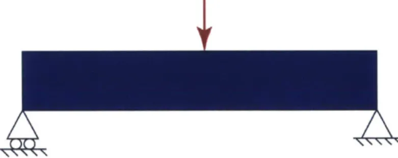
3.4.4 Beam Bending Exam ple... 42
3.4.4.1 Problem Form ulation ... 42
3.4.5.1 Inspiration Based Design ... 45
3.4.5.2 Traditional Manufactured Design... 46
3.4.5.3 Additive Manufactured Design ... 48
3.4.6 P roposed Process:... 49
3 .5 C o n clu sio n ... 5 1 Chapter 4: Applying an AM Aligned Design Methodology... 52
4 .1 C ase S tu dies ... 52
4.1.1 Spinning M irror ... 52
4.1.2 GrabCAD GE Engine Bracket... 59
4.1.3 Methodology Implementation Challenges ... 65
4.1.3.1 Difficulties Associated with Function-Based Design ... 65
4.1.3.2 Software Limitations ... 65
4.1.4 Adapting Topology Optimization for AM... 66
4.1.4.1 Lattice-Based Topology Optimization Interpretation... 66
4.1.4.2 Lattice Generation and Sizing ... 67
4.1.4.3 Manufacturing Constraint Integration ... 67
4.1.4.4 Interactive Optimization ... 67
4 .2 C o n clu sio n ... 68
4.2.1 Effective Methodology... 68
P ro cess ... 6 9 5.1 Design Process Versus Development Process... 69
5.2 Economics of Rapid Manufacturing... 70
5.2.1 Economics of Tool-Free Production... 70
5.2.2 Supply Chain, Distribution and Inventory... 70
5.2.3 The Effect of Rapid Manufacturing on Product Development ... 71
5.2.4 The Elimination of the Manufacturing Cycle ... 71
5.2.5 Benefits of the Perfect Prototype ... 72
5.3 Evaluating the Magnitude of the Benefits of Rapid Manufacturing... 73
5.3.1 Economic Impact on Product Development Process ... 74
5.3.1.1 Quantifying the Benefit of Prototype Fidelity ... 74
5.3.2.1 E ffect of N on-Frozen D esign... 75
5.3.2.2 H ardw are Follow s Softw are ... 75
5.4 Innovative Product D evelopm ent... 76
5.5 Conclusion: ... 77
Chapter 6: C onclusion ... 79
6.1 Future w ork ... 79
6.2 Fusion of D esign and D evelopm ent ... 80
A ppendix: G E- G rabCA D Contest Info... 81
List of Figures
Figure 1: Breakdown of utilization of AM in 2014. Based off of data from the Wohlers
R ep o rt 20 14 [7]... 19
Figure 2: The relationship between utilized part strength, complexity and function of AM p arts... 2 1 Figure 3: The increase in spending at service bureaus on end-use parts. Source: Wohlers R ep o rt 2 0 14 [7]... 2 7 Figure 4: Effect of orientation on support structure. Blue is the part material and yellow is support material. Note the effect digital of design in the representation of the fillet, outlined with red, and of the sensitivity to overhanging structures and the required sup p ort m aterial... 34
Figure 5: Natural root system compared to engineering run and shaft design... 37
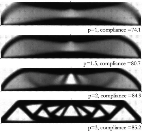
Figure 6: (a) size optimization, (b) shape optimization, (c) topology optimization. Source: B en d so e [4 5]... 4 0 Figure 7: Beam bending problem formulation: design region, loads and boundary conditions. ... 4 2 Figure 8: Topology optimization output as a function of penalty value with virtual density shown as a grayscale and compliance reported - 3... Figure 9: Beam bending results thresholded at 0.3 with varying penalty weighting... 44
Figure 10: Inspired design based off topology optimization... 45
Figure 11: Flow diagram for inspiration based use of TO... 46
Figure 12: Traditionally manufacturable design based on TO... 47
Figure 13: Traditional manufactured design topology optimization flow chart... 47
Figure 14: AM manufacturable design based on TO ... 48
Figure 15: AM topology optimization flow chart. ... 49
Figure 16: Mirror bounding volume in cross section: Red portions define mechanical interface regions that cannot be modified and blue portions are mirror faces and cannot be altered. The central void houses the drive motor and is unavailable. Green represents the available design volume... 53
Figure 18: Top view of with symbolic boundary conditions; disconnected hub (left),
modified load case and connected hub (right). ... 55
Figure 19: One-quarter mirror model showing displacements normal to the x-face (right); red regions do not meet specifications. Left, initial design directly from thresholding; right, post processed resulting in
0.79%
weight increase... 56Figure 20: One-quarter model of final mirror design displacements normal to the x-face (right); faces m eet surface figure specifications... 57
Figure 21: Addition of a boss to accommodate a balancing setscrew in 3-Matic STL ... 58
Figure 22: Traditional mirror design on left, additive mirror design on right. ... 58 Figure 23: AM Optimization flow chart, with backward red arrows representing required
reform ulation experim entation. ... 59
Figure 24: Four load conditions for the bracket. Source [54]. ...
60
Figure 25: Resulting geometry from TO optimization... 61
Figure 26: Isometric view of the final design with VonMises stress displayed. Maroon
colored elem ents represent yielded m aterial... 62
Figure 27: Bottom view of the final design with VonMises stress displayed. Maroon colored elem ents represent yielded m aterial... 62
Figure 28: Comparison of topology optimized design with top three designs from the
competition, displaying percent weight reduction. ... 63
Figure 29: Comparison between TJ2 and T20 design showing stresses viewed from the bottom. Maroon colored elements represent yielded material in upper two images. Red stress represents 500 MPa in the lower two images. ... 64
Figure 30: Density versus Young's modulus plot. Source: Bendsoe [45]... 66
Figure 31: Development process for both AM and conventionally manufactured parts.Unlike traditional manufacturing, AM does not require a separate manufacturing cycle. S o u rce: [3 5]... 72
Figure 32: Prototype Fidelity verus number, holding savings near constant. Source: Thomke an d B ell, [6 7]... 74 Figure 33: Left: Radiolaria an interactive design tool to create necklace [68]. Right: Hyphae
Chapter 1: Background on Additive
Manufacturing
1.1 Introduction:
This thesis will explore how design and development processes can be modified to better harmonize with Additive Manufacturing (AM). Additive Manufacturing will be
discussed in four categories based on utilization: visual model, fit check prototype, pattern or fixture and end-use part. There will be an additional focus on Rapid Manufacturing (RM); the practice of using AM to fabricate end-use parts. RM is particularly interesting, because when fabrication technologies transition to use in manufacturing, the investment of time to optimize design and development becomes important. Finally, a function-based design methodology for RM design based on structural optimization will be presented, formalized and then applied to two case studies.
This thesis is organized into five chapters. The first chapter examines important terminology of AM, how it has been used historically and how it is currently being used. The
second chapter focuses on the growth in the use of RM, the significance of this growth, and includes a formal statement of the thesis's research questions. The third chapter presents background on design and optimization relevant to the thesis' proposed methodology. The methodology is applied to two case studies and results are reviewed in detail in Chapter 4.
Chapter 5 examines the higher-level effects that AM and particularly RM can have on the development process.
1.2 Additive Manufacturing Terminology
1.2.1 Types of Manufacturing Processes
Manufacturing can be divided into three categories: subtractive, formative, and additive. Subtractive manufacturing comprises any process in which parts of a larger section of material are removed to produce an end product. Examples are numerous, reaching as far
back as the fabrication of arrowheads in the Stone Age and extending through modern diamond grinding with accuracy on the order of angstroms [5]. Subtractive manufacturing serves as the benchmark for all manufacturing and, although it has the greatest precision, it is time consuming and requires more starting material than the final product.
Formative manufacturing is usually mold-based or pattern-based with the final parts produced indirectly. Examples of formative manufacturing processes include casting, injection molding and forging. A critical advantage of this method is its efficiency for large-scale production: a single mold or pattern can be used to produce very large numbers of parts.
An Additive Manufacturing process is one in which material is selectively placed to form the final part. An example of this type process is brick and mortar construction. A key advantage in an additive process is the ability to create structures of much greater complexity than could be created by subtractive or formative manufacturing. This complexity is enabled
by the fact that internal features are accessible during fabrication.
1.2.2 Computer- Controlled Additive Manufacturing
Charles Hull's 1984 patent filed for photopolymeric construction of 3D parts and marked the beginning of Additive Manufacturing [6]. Terminology has evolved with the technology, first coalescing around Rapid Prototyping (RP), and then in an effort not to pigeonhole the technology for developing prototypes, the term Additive Manufacturing
(AM) was born. It is important to distinguish this AM terminology from the
previously-discussed Additive Manufacturing processes. The distinction is made in addition to selective material placement already mentioned the process be driven by 3D modeled data. The American Society for Testing and Materials (ASTM) F42 committee, the recognized body
for material, manufacturing and testing standardization, defined Additive Manufacturing as "a process of joining materials to make objects from 3D model data, usually layer upon layer, as opposed to subtractive manufacturing methodologies [1]." While industry has adopted AM, the media has used 3D printing (3DP) as the terminology of choice. Originally a
descriptor for a specific process, 3D printing evokes for the layperson the concept of the technology and has gained widespread acceptance. Recently, Terry Wohlers, a key industry analyst, declared in his annual report of the industry that Additive Manufacturing and 3D
printing can be used synonymously [7]. Similarly, this thesis will use AM and 3DP interchangeably.
In addition to the various names for Additive Manufacturing as a whole, there is terminology for each specific technology or class of technologies within AM. This plethora of terms is further complicated by the fact that almost every company has a trademarked name for their specific process. These processes may not necessarily be unique, resulting in the creation of many names with the same meaning. In an effort to create standard
terminology to reduce confusion, the ASTM organized and defined seven categories that encompass every current methodology for 3D printing [1]. These various approaches rely on different physical phenomena and, as a result, often work with different materials that
exhibit both strengths and weaknesses across cost, rate, quality or material availability. Chapter 4 describes two case studies in which the technology used is metal Powder Bed Fusion (PBF) an Additive Manufacturing process in which thermal energy selectively
fuses regions of a powder bed.
1.2.3 Use of Additive Manufacturing
1.2.3.1 Four Categories of Utilization
Additive Manufacturing has been employed in a wide range of applications. By teLguiizing hese applicationis, we can gain insight into its historical use and how that use is evolving. Here we propose that the use of Additive Manufacturing can be broken into four different categories: visual models, fit check prototypes, fixtures and patterns, and end-use parts. Based on data from an organizational survey by Wohlers Associates, utilization by the four proposed categories is captured in Figure 1.
8
17
w Visual Models
29 I Fit-Check
20 Fixtures & Patterns F End-Use Parts
SOther
26
Figure 1: Breakdown of utilization of AM in 2014. Based off of data from the Wohlers Report 2014 [7].
The utilization is split quite evenly between visual models, fit check prototypes, fixtures and patterns and end-use parts. An expansion of the description of each of the use categories are presented below.
1.2.3.2 Visual Models
The earliest use of Additive Manufacturing was for the creation of physical models designed from computer aided design (CAD) files. A visual model has the form but not necessarily the function of the final part. As such, the value of a model is to provide a mechanism for tactile representation that can be visualized and handled, helping gain
management or customer approval of a design in a medium that can be easily evaluated. And for engineers, it offers an opportunity to get a physical sense of dimensions and an intuitive sense of the design [7].
1.2.3.3 Fit-Check Prototypes
Fit-check prototypes give the user an opportunity to establish appropriate part fit and to assess whether there is sufficient space and access for assembly. This application can be useful both for ensuring that tolerances are correctly accounted for and, in the case of mating to preexisting parts, that interfaces and fits are correct. Frequently, fit-check prototypes will reveal errors that would be expensive in production but can be
1.2.3.4 Fixtures and Patterns
For fixtures and patterns, Additive Manufacturing is used to generate the geometry but not the final part. Due to limitations in materials available for Additive Manufacturing, it is often desirable to prototype or manufacture in a standard engineering material instead. In these cases, parts can be printed and then, using an intermediate process, transformed into a final part. For example, wax positives can be printed and then processed by lost wax casting into metallic parts. Fixtures for assembly or fabrication can also be made to speed up alignment of parts during assembly or to provide a template for manual fabrication procedures.
1.2.3.5 End-Use Parts
For end-use parts, Additive Manufacturing generates both the geometry and material for the final part. After removal from the printer, the part will be utilized directly. End-use part production was the last category of use to be developed but is now exhibiting the most rapid growth, as will be discussed in Chapter 2. In addition to being used for prototypes, end-use parts can be manufactured in quantity as the final product.
1.2.3.6 Influences on Part Utilization
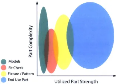
The material and machine properties in Additive Manufacturing have advanced tremendously since the 1980s when brittle plastic was the standard material [6]. At the time, there was a widespread anecdote that models passed around a boardroom rarely made it back to the presenter in one piece. Research since then has led to increasingly durable and diverse materials. Now, parts are made with super alloys, engineering grade thermoplastics, and even living cells [8]. From a design perspective, great improvements have swept the computer industry, transforming the capabilities of CAD and thereby allowing greater complexity and sophistication of part design. By looking at the material requirements and part complexity of AM, we can get a sense of how the utilization has evolved. A conceptual plot of part function based on complexity and utilized strength is shown in Figure 2.
E
Models Fit Check
Fixture / Pattern
End Use Part
Utilized Part Strength
Figure 2: The relationship between utilized part strength, complexity and function of AM parts.
Through this lens of part utilization we see that the evolution of part use is a function of both the complexity that could be effectively captured digitally via software and the part strength or material properties that could be fabricated. The least rigorous
requirements for both strength and complexity only allow for the generation of models of which the primary goal is to physically produce a digital concept. For this purpose material properties are not critical and the value is a function of the complexity and realism that can be captured. For fit-check parts, complexity is not as great since all features need not be captured and the geometry will be limited by traditional manufacturing. However, there is still some level of handling strength required for fit check parts. For fixtures, the material properties become much more important as parts will now be handled aggressively during assembly or production; for patterns, the material properties are critical for processes such as investment casting where material must be melted for removal. End-use parts utilize the most strength and can leverage the greatest complexity providing the opportunity to create parts with the most significant impact.
1.3 Rapid Manufacturing
1.3.1 Definition of Rapid Manufacturing
Rapid Manufacturing is a term that was popularized in the early 2000s and developed from "rapid prototyping [9]." RM can be defined as "the use of a ... CAD-based automated
Additive Manufacturing process to construct parts that are used directly as finished products or components [3]."
1.3.2 Adoption of Rapid Manufacturing
In many cases, Rapid Manufacturing has grown organically from the use scenarios in which a user, under time pressure, took a model that was designed for fit-check purposes
and tested if it had the strength to be functional. These tests were often successful, which demonstrates the utility of RM. Yet, to better understand the current level of adoption of Rapid Manufacturing, it is useful to further examine its advantages and challenges.
1.3.3 Advantages of Rapid Manufacturing
A great deal of literature on Additive Manufacturing has focused on the advantages
and disadvantages of the process. A concept has arisen based on the characteristics of AM: Design For Additive Manufacturing (DFAM), which is central to utilizing the advantages and minimizing the disadvantages of the AM process. The comprehensive list of the benefits and drawbacks RM has been informed by my own personal experience with AM tools, discussions with experts and many valuable sources [3,9-21].
1.3.3.1 Geometric Freedom
Geometric freedom is one of the most far-reaching and significant advantages of AM because, for the first time, form can be decoupled from fabrication. While specific additive processes may have manufacturing restrictions, they are dramatically less
constraining than any previous manufacturing technology. And with this geometric freedom comes a host of benefits that have profound implications:
* Static assemblies can be reduced to single parts.
* Single-Part Assemblies can be fabricated-an assembly grown as a single part with moving subcomponents.
* Mass customization is possible, and large numbers of similar parts can be created in which each part is unique.
* Parts can be optimized for functionality instead of manufacturability, enabling higher performance.
1.3.3.2 Mold-Free Manufacturing
Since the part geometry is defined by digital files and realized with an Additive Manufacturing system, molds are not required and therefore manufacturing is scale invariant. New parts can be created more quickly than previously possible and changes can be made inexpensively and expeditiously. As a result:
* The time to reach market is faster.
* Designs do not need to be frozen after tools are made.
* Factories become more agile since part mix can be varied without retooling.
1.3.3.3 Development benefits
An important and often overlooked impact of using RM is the effect that it has on the development process. More detail on these claims will be presented in the fourth chapter. Generally the advantage of using RM for development can be described as:
e Faster development times of products.
* Perfect fidelity prototypes result when using Rapid Manufacturing. * Late stage changes can be made without excessive costs.
1.3.3.4 Supply Chain, Distribution and Inventory
Rapid Manufacturing enables a leaner supply chain since goods can now be
fabricated on-site and on demand. Transport is simplified, requiring only the distribution of raw materials.
e Reduced inventory since there is no need to store a diversity of parts. * Faster distribution since parts can be built on site.
1.3.4 Challenges
As a young manufacturing technology, the challenges of Additive Manufacturing are just beginning to be understood well, and solutions or mitigation techniques are under development. This section below will enumerate these challenges.
1.3.4.1 Materials
The process requirements for Additive Manufacturing and the specific requirements of the wide range of different AM technologies used have given rise to extensive materials research. Different processes are often suited to specific materials or generate material microstructures with different properties than previously encountered. This has given rise to:
* Requirement for process specific material development. * The qualifications of novel materials.
e Experimentation into process-material interactions. 1.3.4.2 Layer Based Process
Due to the layer-by-layer process employed by Additive Manufacturing, bonding within layers and between layers may be different, leading to anisotropic materials.
Additionally, point-wise manufacturing means that a region may have different properties than its neighbors. More specifically:
* Parts built will have anisotropic material properties requiring more detailed characterization.
* Defects can occur at interior locations of a part, making them difficult to detect. * The stair-stepping, also described as figure error, effect prevents smooth profiles
from being generated in the z-axis due to discontinuities between layer profiles.
1.3.4.3 Process Limitations
The limitations that will be the most difficult to mitigate are those linked to process physics itself. As a result, these limitations may force us to adapt the design and adjust our requirements.
* Surface finish is typically worse than traditionally manufactured parts. * Process times are usually slower than traditional manufacturing. * Support material required for complex overhanging shapes.
1.3.4.4 Part Qualification
Qualification of parts has been difficult given the unknowns in materials, process parameters and machine reliability. As a result, users have been reluctant to put AM parts into critical applications. Recent application of AM parts for end-use has lead to focus on:
* The development of qualification standards and procedures.
* Study of the variability of material properties with as a result of geometry. * Lack of repeatability between parts.
1.3.4.5 Inspection
The benefits that Additive Manufacturing provides from a geometric freedom standpoint also create challenges from an inspection standpoint. Every detail is another feature to measure. The need to inspect parts has typically been focused on the exterior of a part where the
limits
for traditional manufacturing serve to ensure access for measurement. Verifying the detail of internal features is limited by the resolution of the most advanced inspection technologies and the geometric freedom of AM enables the creation of parts thatexceed that inspection resolution. Recent developments in Computed Tomography (CT) are helping study certain material parts [22]. White light imaging is similarly helpful for analyzing complex 3D shapes, but state of the art measurement of internal and complex features is still trailing the technology that can fabricate it [23]. In situ part monitoring is under
development as an alternative to inspection after fabrication, this holds great promise because it allows for inspection of the interior of complex parts during fabrication [24,25]. 1.3.4.6 Process Knowledge
Additive Manufacturing is still in its infancy. Processes are being studied and new features continue to emerge; practitioners have yet to fully understand how to leverage all of the positive elements and how to mitigate the impact of the challenging features. Rapid
Manufacturing has been most successful as engineers have learned how to target some of the design and performance benefits while solving certain qualification issues.
1.4 Conclusion:
The DFAM framework of leveraging the pros and limiting exposure to the cons of AM processing will be critical to understanding the current transformation of AM from rapid prototyping to Rapid Manufacturing. Additionally, the framework provides perspective for examining the design methodology and development process presented in the following chapters. Many of the concepts presented will add another layer to the benefits and
Chapter 2: The Adoption of Rapid
Manufacturing
2.1.1 Tipping the Balance
Until recently, Rapid Manufacturing for end-use parts was an option only for a small niche group of AM users. Continued improvements in materials, machines, and testing methodology have helped drive down the impact of some of the challenges, thereby
reshaping the cost-benefit tradeoff. The resulting shift has been captured by data collected in the Wohlers report, shown in Figure 3, showing how utilization of end-use parts has grown over the past decade.
(A +0 4.4 cd 40 35
1
30 25-20 15-10 2003 2004 2005 2006 2007 2008 2009 2010 2011 2012 2013Year
Figure 3: The increase in spending at service bureaus on end-use parts. Source: Wohlers Report 2014 [7].
Currently, end-use parts represent more than one-third of the business for Additive Manufacturing service bureaus.
- ----28.3 --- ---4.0 --- --- -- -19.6 17.2 4.0 -- -- --- 9. - - -- - - -- - - -- - -8.3
2.1.2 Trend Setting Examples
The most effective utilization of Rapid Manufacturing has been within low-volume manufacturing: taking advantage of the mold-free economics and geometric complexity available through this method. Two industries in particular have successfully utilized these benefits: the medical device market in which prostheses, surgical guides and implants can be customized for customers' specific profiles, and the aerospace industry in which the
geometric freedom has enabled higher performance parts to be developed. In each of these cases, value has not been derived by delivering lower cost manufactured parts but rather through an increase in part performance.
A striking example of the adoption of RM for medical manufacturing has been the
fabrication of hearing aids of which more than ten million of which have been designed and produced to fit into individual patients' ears [26]. The added value of a customized fit and the ability to fabricate replacement units without holding inventory or re-measuring a
person's ears outweighs any additional manufacturing costs. For these reasons it is estimated that 90% of hearing aids are now made with RM, more than two million per year [7].
Rapid manufactured acetabular cups for hip replacements demonstrate another example of geometric freedom providing critical advantages. One of the key benefits of this design over those made via conventional manufacturing is the ability to create a range of densities within the same
part.
Varying density enables the porous side to nrovidean
ontimal site for Osseo-integration (bone growth), while the polished high density side creates an efficient ball and socket joint. Additive manufactured accetabular cups have been implanted in more than 90,000 patients in Europe and recently the FDA has allowed implantation of similar devices in the United States [7,27].Within the aerospace industry, one of the most notable parts being rapidly manufactured is a fuel injector nozzle for the LEAP engine scheduled to enter service in
2016 on Boeing 737 and Airbus A380 airplanes. The utilization of RM to make this part has
received a great deal of press due to the scale of manufacturing and the increased
performance it provides. It will be manufactured in quantities between 20,000 and 50,000 units per year. The highlight of this project is that the new fuel injector, by utilizing
geometric freedom of AM, has reduced an assembly of 20 parts to a single part, resulting in a reduction of mass by 25% and a fivefold increase in durability [28].
2.1.3 Economics of Rapid Manufacturing and the Direct
Substitution Fallacy
Though the following academic research suggests that RM is not cost effective in large quantities, the examples of the fuel injector nozzle and hearing aid have demonstrated that manufacturing products on a scale of tens of thousands to millions can be profitable. A number of studies have explored the manufacturing cost tradeoffs between choosing to manufacture a part by injection molding or Rapid Manufacturing. Two studies: Hopkins & Dickens and Ruffo et al. state that the economical break-even volume between AM and injection molding ranges from roughly 1,000 to 10,000 based on part size [9,19]. More recently, Atzeni et al. conducted similar research focusing on the effect of redesigning the RM part to be better suited for Additive Manufacturing. Their results show that the break-even point for a small part rose to roughly 90,000, demonstrating a substantial shift when the design is tailored for AM [10]. A key limitation of these studies is their assumption that new parts will ultimately perform identically to traditional parts; as we have seen in the preceding examples, this generally is not the case.
Let us formalize this concept that we can define as the Direct Substitution Fallacy, as the belief that Additive Manufacturing can be substituted to create end-use parts without altering designs tailored for traditional manufacturing. Without accounting for this fallacy, analysis is almost without exception a disappointment. Typically, material properties are inferior, costs are higher and tolerances are worse [13,12]. To make up for these deficiencies the part must be redesigned expressly for RM to have a more efficient geometry or an otherwise increased value [11].
2.1.4 Research Questions
This thesis examines the impact that Rapid Manufacturing can have on both the design and development processes. The research into this was motivated by the desire to gain a better understanding in how these two processes can be aligned to the advantages of AM. Specifically, this thesis sets out to answer two key questions:
2. Can the unique characteristics of RM be utilized to enhance the development process?
The third and fourth chapters will focus on answering the first of the questions and will explore how to design parts for RM. A methodology will be proposed that leverages benefits while minimizing the impact of the challenges of AM. Typically, to justify the increased cost of AM parts, a design must outperform conventionally-manufactured designs.
In chapter four, two case studies are explored to illustrate the proposed design methodology and the benefits of its utilization.
The second question will be answered in the fifth chapter, which offers an approach for how one can leverage AM to improve the product development process. We will explore how the development process for Rapid Manufacturing is fundamentally different than that
for conventional manufacturing. And it will be argued that these key differences, when leveraged correctly, can be of substantial financial benefit.
2.1.5 Value Proposition
Research is underway to improve upon current systems to minimize or eliminate the challenges that have restricted the use of Additive Manufacturing technology. Improved material properties, qualification procedures, robust AM systems, and closed loop control systems are all under development. Together, these improvements will shift the value proposition for Rapid Manufacturing and, as a result, pressure will rise to leverage this increasingly robust technology.
A McKinsey & Company survey highlights the lack of organizational readiness for
adoption. The report states, "In essence, more than half of the market has yet to grasp AM's applications [29]." Currently, AM is being heralded as an important new technology based solely on its manufacturing freedom. Yet there is a lack of literature on exploring how best to reshape the design process and the product development process to amplify the benefits. Due to the similarities between AM processes, increased knowledge in this area will apply to all of the various AM processes and will engender increasing relevance as the technology becomes more mature.
Chapter 3: Breaking out of the Mold
3.1 Fighting Against Our Design Instincts
This chapter is divided into two sections and sets out to answer how we can best leverage the benefits of RM during the design process. The first section explores the tools we use for design and how those contribute to the design process. Based on the advantages
and disadvantages of the different tools examined, we propose a methodology of design for AM.
3.1.1 The Design Paradox
For the first time, design has become more challenging than manufacturing. Design and manufacturing have historically been intertwined, typically with the designer pushing the manufacturer to implement increasingly complex designs. Now, that paradigm is reversed. With the development of Additive Manufacturing, it has become possible to fabricate objects of virtually unlimited intricacy leading to the slogan that "complexity is free." But this is only half of the creation process and designing has not become any easier. The reduction of constraints on the manufacturing process shifts the limitations from
manufacturing to design. We are now in a design-limited paradigm where we could make increasingly complex objects if only we could design them. This transition is well captured
by Reeves: "Most products are not optimised, as they are 'designed-for-manufacture' rather
than 'manufactured-for-design [30]."'
3.1.2 Breaking Out of Design Fixation
Currently, a significant limitation in learning to design for Additive Manufacturing is an understanding of how to distance ourselves from past designs. Since design always has to be manufacturable, we design within the regime of the possible as defined by what can be manufactured. In traditional design, consideration is paid to tool access, wall thickness variations, undercuts, draft angles, and a myriad of other factors that are not relevant for 3D
printing. While manufacturing is less restrictive with Additive Manufacturing, assembly constraints remain of critical importance. By carefully considering how something would be made and assembled, Boothroyd and Dewhurst established that savings of 50% over a project life cycle could be realized [31]. Their work demonstrated a significant
interdependence between design, manufacturing, and assembly that has led to greater focus on their interaction.
While 3D printing is not free from restrictions, it has many fewer manufacturing constraints -- and those it has serve mainly as guidelines. Guidelines do not strictly prohibit features but instead increase the cost of the feature, typically driven by build time, post processing and material waste.
To generate complex engineering systems, we often build off past experiences: engineers are taught not to "reinvent the wheel." While such an approach is often beneficial, one often inherits obsolete assumptions tied to traditional manufacturing methods. That phenomenon is referred to as design fixation: when designers are primed with specific concepts that result in a restricted ability to conduct novel design generation. With this fixation, the framing of design problems influences designers,
limiting
the range of their ideas and ability to think creatively [32,33]. And this phenomenon of design fixation is particularly impactful in Additive Manufacturing, where conventional manufacturing experience restricts novel designs that leverage the advantages brought by AM [34].3.2 Design for Manufacturing
3.2.1 Guidelines for Design
To design effectively for RM, engineers must have an intimate understanding of AM technology and its specific constraints. Due to the recent development of AM technology and the diversity of the systems and software available, users must often experimentally determine many of the system constraints. The case studies examined here for this research involve manufacturing using metal powder bed fusion, more specifically Selective Laser Melting (SLM) with an EOS system.
The following set of guidelines for AM are based on authors previous work on the development of an AM Unmanned Air Vehicle (UAV) built with FDM [35]. The design
guidelines were synthesized to assist designers in understanding the fundamental differences between AM design and traditional design. These guidelines have been adapted from FDM to metal PBF, many of the following considerations apply to other AM processes as well:
3.2.1.1 Part Orientation
- The orientation of a part during the printing process impacts many of its final
characteristics; the layer deposition process creates an inherent anisotropy in the part, which may adversely affect its strength properties. In metal, these effects are quite small. For example, Ti6AL4V yield strength differs by only 2%, for FDM ABS-M30 it is 20% and some processes more than 50% [36,37,20].
- Depending on orientation, some features require support material.
e At small scales, print orientation can affect figure error on shapes, such as circles.
3.2.1.2 Digital Design
- Every part has a resolution of a discrete size that is dictated by a physical constant, such the diameter of the laser.
- For very small-scale or thin-walled parts, the dimensions of a sub element must be a multiple of the laser beam spot size.
- The vertical build direction resolution is limited by the layer height.
3.2.1.3 Support Material Plan
* Metallic support material is wasteful; it takes additional material and time to create and must be removed and thrown away after fabrication, requiring handing and extensive processing time.
- The further above the build plane a supported feature is located, the more costly it is since support material propagates through the entire height of the print.
- Depending on geometry, support material may not be required to bridge small gaps. For example, a typically-supported feature, such as a horizontal hole, often can be built support-free with only minor distortion.
3.2.1.4 Overhanging Structures
- The machine can create self-supporting overhangs up to a specific angle; in the case of metallic PBF systems, this angle is roughly 45 degrees from the vertical axis. - The part may be reoriented to eliminate problematic overhangs. Here, the tradeoff
between the two potential configurations must be evaluated -- changes may not necessarily reduce support but instead shift it to another location. Alternatively, the support may be reduced but the build may take longer.
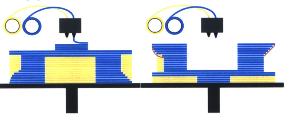
The behavior of Fused Deposition Modeling (FDM) is quite similar to that of PBF in metal. Figure 4 shows the effects of part orientation, digital design, support structures and overhanging structures.
Figure 4: Effect of orientation on support structure. Blue is the part material and yellow is support material. Note the effect digital of design in the representation of the fillet, outlined with red, and of the sensitivity to overhanging structures and the required support material.
In this example, we see the dramatic effect of reorienting the part. In doing so there is a decrease in the overhanging structures and thus in required support structure. The effect of digital design, the discretization of material, is exemplified by the poor representation of the fillet on the left. Finally, the difference between a fillet and chamfer results in dramatic difference in support structure required.
3.3 Design Tools and Design Frameworks
The software tools we use have a strong effect on the types of designs we create. This section examines two different categories of design tools to understand some of the
fundamental differences that exist. Two main categories of tools are: Computer Aided Design tools, where the user models every detail of the design with his or her own hand, and generative Computer Based Design (CBD) tools, where users create computer interfacing rules that in turn generate the parts. An explanation of how bioinspired design and function based design tools fit into the generative category of design tools will also be examined.
3.3.1 Computer Aided Design
Computer Aided Design has advanced dramatically from its origins as a drafting aid, but its fundamental role has always been to help engineers design objects to be physically
realized [38,39]. The implication is that there is no need to be able to model structures that cannot be built. The result has been to develop features that enable engineers to build parts digitally in a way that reflects their physical counterparts and resultant traditional
manufacturing methods [8]. In the common design software, Solidworks, an example of manufacturing influencing a digital tool, the extrude function largely reflects milling operations; revolve similarly reflects turning operations, etc. Historically, the reflection of manufacturing constraints in digital design software has not been problematic since it has not added further restrictions. As we focus on design for Additive Manufacturing, the connection between software and traditional manufacturing greatly restricts our ability to design novel shapes and therefore to think in ways that capture the potential of the new tools. The following subsections represent a survey of design tools and frameworks for addressing the software challenges of AM.
3.3.2 Animation Software
The manufacturing bias in software described above is a product of the
fundamentals of engineering; animation software, on the other hand, which considers design without the intent of fabrication. Animation software enables us to investigate design tools
free from the influence of manufacturing bias. This different end-goal has resulted in the creation of a dramatically different tool, one that has a great deal more flexibility but typically creates only the surface meshes required to produce animations. An example of this freedom can be seen in Autodesk's Maya software. Within Maya, the this is particularly apparent in the XGen tool, which uses rules and guide curves to build arrays of objects on top of
existing surfaces [40]. The XGen is often used for the creation of hair or foliage but could be envisioned as a method to generate surface textures on a part for printing or as a framework for lattice generation. While there are a lot of important elements that can be taken from animation software as a class of design tools, the use of surface meshes can present problems when creating models for 3D printing.
3.3.3 Complexity, Simplicity and Biomimicry
"Complexity is free," an often-espoused mantra for AM, may be true from a manufacturing perspective, but it is not from a design perspective. Each detail costs
computation power, yielding models that become burdensome during design and sometimes too complex for converting the file from geometry to tool paths for printing. We can expect in the future that software will more efficiently address complex 3D structures and that computer power will continue to increase, lessening these effects. Beyond the increased processing power required for traditional CAD, each detail requires time by the designer to create it.
Simple designs are faster to create, cheaper to make, easier to understand, and quicker to communicate. They are developed more quickly since creators can explain the designs to peers more effectively, interface with analysis teams more easily, create drawings
for manufacturing teams more swiftly, and create tooling that will be easier to design and fabricate. As a result, most designed objects have straight lines and simple curves, and deviate from this form only when there is a design constraint. Yet each of these ideals is founded in a paradigm of traditional manufacturing where each detail, if removed, will create a simpler, cheaper and often more effective design.
Over the last 70 years there has been a push to explore nature as inspiration for engineering through bionics, biomimicry and biomimetics as a way to leverage the evolutionary advantages that nature has developed [41]. This discipline evokes the
comparison of human and natural design, one in which we see fundamental differences. As we compare man-made designs to those of nature, we find that the simplistic straight lines and right angles common to human design are a rarity in nature. When analyzing the design of natural systems, we quickly reach our limits of understanding. The systems are often so complex and made up of so many different elements that we struggle to grasp the design intent and sometimes even the environmental pressures that guided it. As a result, we often implicitly accept that evolution has demonstrated the functional efficacy of the organism or feature even though we may not completely understand its function. Frequently, in bio-inspired design, the most challenging step is to understand the significance of the mechanisms of the natural system so that they can then be distilled and translated into a mechanical design [42].
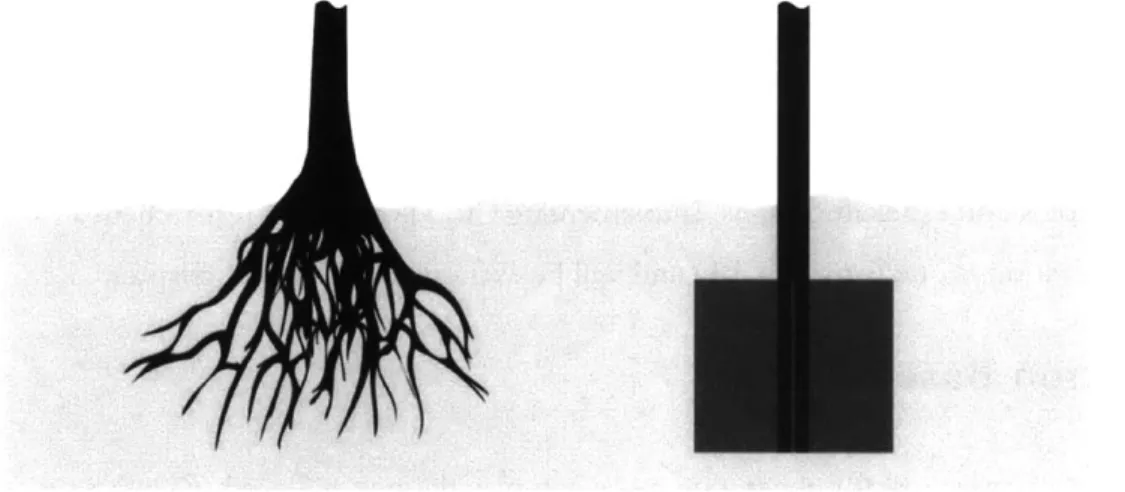
As an example, let us consider a design exercise asking us to create a foundation for a tall vertical cantilever beam subject to wind loading that uses a minimum of material. Nature grows a tree with a complex root system that anchors it into the earth. As a human designer we might extend the cantilever beam deep into the ground and affix it with four fins to increase its exposed surface area, a depiction of this is shown in Figure 5.
Figure 5: Natural root system compared to engineering run and shaft design.
Clearly, in this problem there is a tradeoff between design complexity and performance. As designers, if we assume that the root system requires half as much material as the finned beam design, we find ourselves in a bind: we would like to take advantage of the increased efficiency of the root system but are unable to create it. There is no technology that can fabricate a root system, and this represents the point at which the discussion usually ends.
structure, AM introduces fabrication capabilities for detail on the level of a root system. The greater challenge that still remains, yet is rarely discussed: design the root system.
If we consider the future feasibility of manufacturing, we must consider how design
may work. Programming could be used as a tool for design; we can envision that a person could design a fractal-based algorithm that would generate a custom sized "root" system for the cantilever beam. Computers could be used as part of the creative design process, a fundamentally different usage from how we have designed historically. In this generative paradigm we can create rules for a system that governs its behavior rather than explicitly
defming it.
3.3.4 Computer-Based Design
Let us shift our focus from computer-aided design to computer-based design, which is a less well-known term in the field. CAD tools primarily focus on creating a more
streamlined design process and increasing efficiency [38]: the goal is to realize the designer's intent more efficiently than manual drafting, akin to how a word processor improves upon
the efficiency of a typewriter. The term Computer Based Design, coined by Mistree and Muster, focuses on utilizing computers differently for design [2]. In computer-based design, substantially more work is shifted from the designer to the computer. Now, not only can design software aid in realization of concepts, it can be one of the drivers in creating increasingly complex and efficient designs. Implementing CBD is an active research area. Structural optimization is one form of CBD and will be examined later in this chapter.
3.3.5 Function Based Design
To create a framework for generating more complex designs, we need to shift how we define design problems such that computers can be more integrated in the process. During the design process, we generate lists of functional requirements, but those lists are not necessarily comprehensive and, more insidiously, they are often arbitrary. This lack of rigor in framing the design problem functionally is mitigated by two factors; the designer's interpretation of the requirements and the explicit generation of forms by the designer. If we move towards a function-based design, we must instead strive to carefully understand the needs of the design problem rather than an explicit vision of its potential form.
If the input of the design process can subtly shift from explicit forms to
requirements, the opportunity exists to envision a much more powerful parametric design tool. This tool, instead of being driven by variable dimensions, could be driven by variable function requirements, such as forces on the structure and boundary conditions. Here, the user would proceed in a similar fashion to how a designer now parametrically adjusts
dimensions. With this methodology, design would be explored by investigating how changes to loading, objective, and constraints on the problem affect the design's form. While CAD tools focus on increasing designer productivity, they do little to alter the type of output. CBD tools not only begin to increase productivity but also foster a new design methodology and a path for the generation of new forms. Topology optimization is a CBD tool that is
currently gaining traction in structural optimization.
3.4 Structural Optimization
3.4.1 History of Structural Optimization
Structural optimization is a function-based design approach driven by a set of constraints and an objective function. The optimization process centers on minimizing the objective without violating the constraints. A key contribution to the field of structural optimization came in 1904 when Michell published "The Limits of Economy of Material in Frame-structures." This work laid the foundation for structural optimization by
demonstrating several analytically-optimized structures and developing some rules which govern optimized structures [43]. His work on analytical optimums of structures were limited by the complexity of hand calculations, but could be built upon to explore a more
diverse range of problems with the introduction of computers. The initial examples that Mitchell produced remain relevant today as benchmarks for many algorithmic solvers.
3.4.2 Optimization Engine
To conduct structural optimization, two distinct modules of software are required. The first is an analysis module, typically a finite element analysis (FEA) tool that is capable of determining the behavior of a structure. The second is an optimization module that uses
the data created by the finite element analysis tool to modify the design and submit it for reanalysis. The optimizer often takes advantage of a subroutine that conducts a sensitivity analysis of the problem to guide the software as to what variables to modify [44].
3.4.3 Types of Optimization
For structural optimization, it is common to break the field into three distinct categories: size, shape, and topology. The following diagram shows schematics for the three main optimization techniques as illustrated by Bendsoe.
(a)
(b)
(c)
Figure 6: (a) size optimization, (b) shape optimization, (c) topology optimization. Source: Bendsoe [45].
3.4.3.1 Size Optimization
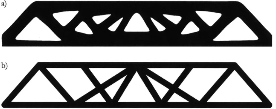
Size optimization is the simplest type of optimization; it centers on the relative sizing of specific structural members. In the case of a truss, the cross section of each member is adjusted to match the load passing through it. The result is that the original layout or shape of the truss remains, but individual elements are resized creating a system that best fulfills the optimality criteria.
3.4.3.2 Shape Optimization
Shape optimization enables changes to the form of an object within certain
boundaries. For this process, the topology of the part, the edges, and holes remain constant while the position and dimensions of the design are adjusted and optimized. This process is achieved by adjusting the surfaces of a 3D model or the edges of a 2D model (as seen in Figure 6 above).
![Figure 1: Breakdown of utilization of AM in 2014. Based off of data from the Wohlers Report 2014 [7].](https://thumb-eu.123doks.com/thumbv2/123doknet/13926821.450264/19.918.142.570.129.357/figure-breakdown-utilization-based-data-wohlers-report.webp)
![Figure 3: The increase in spending at service bureaus on end-use parts. Source: Wohlers Report 2014 [7].](https://thumb-eu.123doks.com/thumbv2/123doknet/13926821.450264/27.918.111.627.528.893/figure-increase-spending-service-bureaus-source-wohlers-report.webp)