Publisher’s version / Version de l'éditeur:
Vous avez des questions? Nous pouvons vous aider. Pour communiquer directement avec un auteur, consultez la
première page de la revue dans laquelle son article a été publié afin de trouver ses coordonnées. Si vous n’arrivez pas à les repérer, communiquez avec nous à [email protected].
Questions? Contact the NRC Publications Archive team at
[email protected]. If you wish to email the authors directly, please see the first page of the publication for their contact information.
https://publications-cnrc.canada.ca/fra/droits
L’accès à ce site Web et l’utilisation de son contenu sont assujettis aux conditions présentées dans le site LISEZ CES CONDITIONS ATTENTIVEMENT AVANT D’UTILISER CE SITE WEB.
ICAST2011, The 22nd International Conference on Adaptive Structures Technologies [Proceedings], 2011
READ THESE TERMS AND CONDITIONS CAREFULLY BEFORE USING THIS WEBSITE. https://nrc-publications.canada.ca/eng/copyright
NRC Publications Archive Record / Notice des Archives des publications du CNRC : https://nrc-publications.canada.ca/eng/view/object/?id=58aee064-fae8-46bd-9124-1403842fb149 https://publications-cnrc.canada.ca/fra/voir/objet/?id=58aee064-fae8-46bd-9124-1403842fb149
NRC Publications Archive
Archives des publications du CNRC
This publication could be one of several versions: author’s original, accepted manuscript or the publisher’s version. / La version de cette publication peut être l’une des suivantes : la version prépublication de l’auteur, la version acceptée du manuscrit ou la version de l’éditeur.
Access and use of this website and the material on it are subject to the Terms and Conditions set forth at
Intelligent control of smart actuators in a new closed loop morphing wing mechanism
Grigorie, Teodor lucian; Botez, Ruxandra Mihaela; Popov, Andrei Vladimir; Mamou, Mahmoud; Mébarki, Youssef
Intelligent control of smart actuators in a new closed loop morphing wing mechanism
L.T. Grigorie (a), R.M. Botez (a), A.V. Popov (a),M. Mamou (b), and Y. Mébarki (b)
(a) École de Technologie Supérieure, Montréal, Québec H3C 1K3, Canada (b) National Research Council, Ottawa, Ontario K1A 0R6, Canada
The objective of the research presented here is to develop a new morphing mechanism using smart materials such as Shape Memory Alloy (SMA) as actuators and fuzzy logic techniques. These smart actuators deform the upper wing surface, made of a flexible skin, so that the laminar-to-turbulent transition point could move close to the wing trailing edge. The ultimate goal of this research project is to obtain a drag reduction as a function of flow condition by changing the wing shape. The transition location detection is based on pressure signals measured by optical and Kulite sensors installed on the upper wing flexible surface. Depending on the project evolution phase, two architectures are considered for the morphing system: open loop and closed loop. The difference between these two architectures is given by the use of the transition point as feedback signal. This research work was a part of a morphing wing project developed by the Ecole de Technologie Supérieure in Montréal, Canada, in collaboration with the Ecole Polytechnique in Montréal and the Institute for Aerospace Research at the National Research Council Canada (IAR-NRC).
Recently, morphing wing system studies have branched out into new research directions. Extremely complex and catalogued as inter- and multidisciplinary studies, morphing wing studies continue to ‘push’ the science, up to the extreme boundaries of mathematics and physics. These multidisciplinary studies therefore require knowledge in the following disciplines: aerodynamics and computational fluid dynamics, aeroelasticity, automatic control, intelligent materials, signal detection using the latest miniaturized sensors, high computer-time calculations, wind tunnel and flight testing, instruments, and signal acquisition - these signals have such speed that they are raising serious problems for the existing calculus technology. Consequently, real-time system functioning is conditioned (in addition to other factors) by the obtaining of the best data processing algorithms, easy to implement software within the command and control unit. Fuzzy logic theories, which offer remarkable facilities, may therefore be used in these algorithms. They facilitate signal processing by allowing empirical models to be designed based on experimental data; and thus, the complex mathematical calculus currently in use can be avoided. In addition, fuzzy logic can be used to model highly non-linear, multidimensional systems, including those with parameter variations, or where the sensors’ signals are not accurate enough for other models. This research project included the following: optical sensor selection and testing for laminar-to-turbulent flow transition validation (by use of XFoil code and Matlab), smart material actuator modeling, aeroelasticity wing studies using MSC/Nastran, open loop and closed loop transition delay controller design, integration and validation on a wing equipped with SMAs and optical sensors.
A first phase of this project involved the determination of optimized airfoils available for 35 different flow conditions expressed in terms of five Mach numbers and seven angles of attack combinations. The optimized airfoils, derived from a laminar WTEA-TE1 reference airfoil (Fig. 1), were calculated and were used as a starting point in the actuation system design. Two steps were completed in the actuation system design phase: optimization of the number and positions of flexible skin actuation points, establishment of each actuation line’s architecture (Fig. 2). The next phase of the project was about the design of the actuation control in open loop architecture of the morphing wing, for which an integrated on-off versus a fuzzy PID architecture was chosen (Fig. 3 to Fig. 5). In this design, numerical simulations of the open loop morphing wing integrated system, based on a SMA non-linear model, were performed; as subsequent validation methods, a bench test (Fig. 6, Fig. 7) and a wind tunnel test were conducted (Fig. 8, Fig. 9). In the final phase a closed loop controller was developed and experimentally validated (Fig. 10-Fig. 13).
Fig. 1 Morphed airfoil shapes for different flow cases
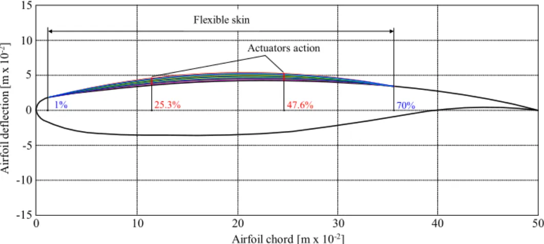
Fig. 2 Model of the flexible structure
Fig. 3 Operating scheme of the SMA actuators control
1% 25.3% 47.6% 70% Actuators action Airfoil chord [m x 10-2] Air fo il def lec ti o n [ m x 10 -2] 0 10 20 30 40 50 -15 -10 -5 0 5 10 15 Flexible skin airfoil leading edge Airfoil lower surface (rigid) Actuation points First actuating line From power
supply #1 From powersupply #2
Second actuating line Gas springs SMA actuators Airfoil trailing edge Airfoil uper surface - flexible
skin part (morphed) Airfoil uper surface(rigid part)
roller rod cam , M, Re Pilot Control Flight conditions Optimised airfoils database dY1opt dY2opt Real airfoil Integrated controller dY1real dY2real SMA actuators
e=dYopt- dYreal
Airflow perturbations Current Position transducers dY1real dY2real
Fig. 4 The simulation model for the controlled SMA actuator
Fig. 5 The fuzzy PID architecture
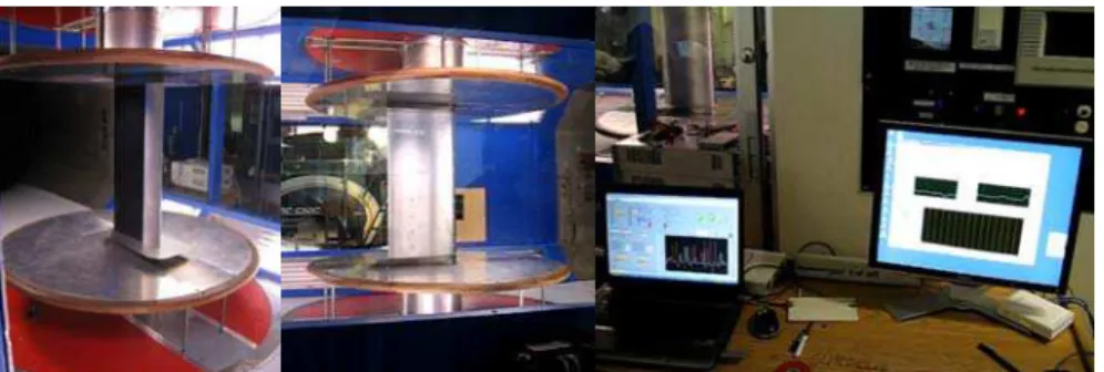
Fig. 6 Morphing wing system in the bench test runs
Temperature [K] skin deflection [mm] skin deflection [mm] desired deflection [mm] SMA elongation [m] skin deflection [mm] 0 skin deflexion [mm] 1 1 4.5 desired skin deflection [mm] 3/1000 cam factor mm to m XY Graph Scope 0.078 SMA max set
[m] 0 SMA elongation [m] Current Force Displacement Temperature SMA Model 1.8 SMA Initial length [m] 1.8 SMA Initial length Diff error Temperature Current out Integrated controller Memory F aero [N] x [m] F SMA [N] y [mm] Mechanical system 0 Current [A] 273.15 Celsius to Kelvin 1500 Aerodynamic force [N] Current 1 Current out Temperature limiter Switch -K-P Gain 1/s -K-I Gain -K-General Gain -1 Gain Fuzzy Logic Controller du/dt -K-D Gain 0 Current in cooling phase Current saturation 0 Current when reached limit Add1 |u| Abs 2 Temperature 1
Diff error Current
Fig. 7 Bench test results for α=0°, M=0.225 and for α=1°, M=0.3 -1 0 1 2 3 4 5 20 30 40 50 60 70 80 50 100 150 200 250 300 350 0 Time [s] act #1 act #2 50 100 150 200 250 300 350 0 Time [s] act #1 act #2 Te mp eratu re [ oC] D is p lacemen ts d Y1 , d Y2 ( v ) [mm] =0°, Mach=0.225 Temperature [oC] D is p lacemen ts d Y1 , d Y2 ( v ) [mm] -1 0 1 2 3 4 5 20 30 40 50 60 70 80 act #1 desired act #1 obtained act #2 desired act #2 obtained 50 100 150 200 250 300 350 -1 0 1 2 3 4 5 6 7 8 0 Time [s] 20 30 40 50 60 70 80 90 100 50 100 150 200 250 300 350 0 Time [s] 20 30 40 50 60 70 80 90 100 act #1 act #2 Dis p laceme n ts d Y1 , d Y2 ( v ) [mm] Temp eratu re [ oC] -1 0 1 2 3 4 5 6 7 8 Dis p lacemen ts d Y1 , d Y2 ( v ) [mm] =1°, Mach=0.3 Temperature [oC] act #1 desired act #1 obtained act #2 desired act #2 obtained act #1 act #2
Fig. 8 Wind tunnel morphing wing model
Fig. 9 Wind tunnel test results for α=1°, M=0.2 and for α=2°, M=0.25
50 100 150 200 250 300 350 -1 0 1 2 3 4 5 6 7 8 0 Time [s] D isplace ments d Y1 , d Y2 ( v ) [m m] =1°, Mach=0.2 act #1 desired act #1 obtained act #2 desired act #2 obtained 400 20 30 35 40 45 50 55 65 Time [s] Te mper ature [ oC] act #1 act #2 50 100 150 200 250 300 350 0 400 25 70 60 20 25 35 40 45 50 55 60 -1 0 1 2 3 4 5 6 7 8 D isp lacem ents d Y1 , d Y2 ( v ) [ mm] Temperature [oC] act #1 act #2 30 65 70 -120 25 35 40 45 50 55 60 0 1 2 3 4 5 6 7 9 D isp lacements d Y1 , d Y2 ( v ) [m m] Temperature [oC] act #1 act #2 30 65 8 20 30 35 40 45 50 55 65 Time [s] Temperat u re [ oC] act #1 act #2 50 100 150 200 250 300 350 0 400 25 60 450 -1 0 1 2 3 4 5 6 7 9 D isplacem en ts d Y1 , d Y2 ( v ) [ m m ] 8 Time [s] 50 100 150 200 250 300 350 0 400 450 =2°, Mach=0.225 act #1 desired act #1 obtained act #2 desired act #2 obtained
Fig. 10 Closed loop architecture of the morphing wing
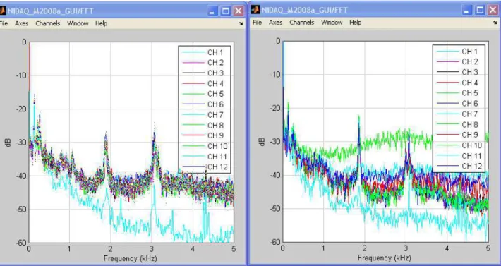
Fig. 11 Pressure signals FFT for un-morphed and morphed wing, for α=0°, M=0.3.
index sensor transition write _profil MATLAB Function retour _pression _2 -K-retour _pression _1 -K-dyn press dY2 -K-dY1 -K-correction -0.29175 channels U S Y uT Subsystem frame const mean rms q Records Rate Transition 1 Rate Transition Periodogram P2 -K-P1 -K-Normalization u u Maximum Val Idx Matrix Concatenate 2 Gains In1 Out1 -K-To Frame FFT Freq Ctl 1 Control SMA y 1 y 2 e1 e2 ctl Pos des #1 Pos des #2 Pos real # 1 Pos real # 2 Temp # 1 Temp # 2 Forces Currents Tensions 1 Analog Input nidaq Dev 1 USB-6210 10000 samples /sec 1-4 U S Y 1-2 U S Y 1-1 U S Y P2 P2 P2 P2 P2 P1 Real wing data
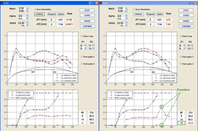
Fig. 12 GUI for un-morphed and morphed wing, for α=0°, M=0.3.
Fig. 13 Wind tunnel test for α=0°, M=0.3 flow condition
=0o, Mach=0.3 -1 0 1 2 3 4 5 6 7 0 100 200 300 400 500 600 700 Di spl ac em ent d Y1 [ mm] Time [s] act #1 desired act #1 obtained act #2 desired act #2 obtained 0 100 200 300 400 500 600 700 Time [s] -1 0 1 2 3 4 5 6 7 8 9 Di spl ac em ent d Y2 [ mm] Transition

![Fig. 7 Bench test results for α =0°, M=0.225 and for α =1°, M=0.3 -101234520304050607080501001502002503003500Time [s]act #1act #2501001502002503003500Time [s]act #1act #2](https://thumb-eu.123doks.com/thumbv2/123doknet/14137772.469935/5.918.100.839.92.958/fig-bench-test-results-time-act-act-time.webp)