Asynchronous Logic Automata
by
David Allen Dalrymple
B.S. Mathematics, University of Maryland Baltimore County (2005)
B.S. Computer Science, University of Maryland Baltimore County
(2005)
Submitted to the Program in Media Arts and Sciences,
School of Architecture and Planning,
in partial fulfillment of the requirements for the degree of
Master of Science in Media Technology
at the
MASSACHUSETTS INSTITUTE OF TECHNOLOGY
June 2008
c
Massachusetts Institute of Technology 2008. All rights reserved.
Author
Program in Media Arts and Sciences
May 9, 2008
Certified by
Neil A. Gershenfeld
Director, Center for Bits and Atoms
Professor of Media Arts and Sciences
Thesis Supervisor
Accepted by
Prof. Deb Roy
Chair, Program in Media Arts and Sciences
Asynchronous Logic Automata
by
David Allen Dalrymple
Submitted to the Program in Media Arts and Sciences, School of Architecture and Planning,
on May 9, 2008, in partial fulfillment of the requirements for the degree of
Master of Science in Media Technology
Abstract
Numerous applications, from performance scientific computing to large, high-resolution multi-touch interfaces to strong artifical intelligence, push the practical physical limits of modern computers. Typical computers attempt to hide the physics as much as possible, running software composed of a series of instructions drawn from an arbitrary set to be executed upon data that can be accessed uniformly. However, we submit that by exposing, rather than hiding, the density and velocity of information and the spatially concurrent, asynchronous nature of logic, scaling down in size and up in complexity becomes significantly easier. In particular, we introduce “asynchronous logic automata”, which are a specialization of both asynchronous cellular automata and Petri nets, and include Boolean logic primitives in each cell. We also show some example algorithms, means to create circuits, potential hardware implementations, and comparisons to similar models in past practice.
Thesis Supervisor: Neil A. Gershenfeld
Title: Director, Center for Bits and Atoms, Professor of Media Arts and Sciences
Asynchronous Logic Automata
by
David Allen Dalrymple
The following people served as readers for this thesis:
Thesis Reader
Marvin Lee Minsky
Professor of Media Arts and Sciences
MIT Media Laboratory
Thesis Reader
Gerald Jay Sussman
Panasonic Professor of Electrical Engineering
MIT Computer Science and Artificial Intelligence Laboratory
Acknowledgments
I am grateful for the support of MIT’s Center for Bits and Atoms and its sponsors.
I would like to thank my thesis supervisor, Neil Gershenfeld, whose suggested reductions to practice and ready-fire-aim methodology helped me move my ideas beyond vague specula-tion. Without his initiative in bringing me to MIT, I would not be here today.
I also thank my thesis committee: Gerald Sussman, who helped limit my goals for this Mas-ter’s thesis, Marvin Minsky, who provided immensely valuable oral history, and unofficially, Ray Kurzweil, who taught me what all this computing will be good for in the future, and Tom Toffoli, who explained to me what computing really means.
I thank those who have worked with me on the Conformal Computing team and discussed these ideas with me, including Kailiang Chen, Kenny Cheung, Ahana Ghosh, Forrest Green, Mike Hennebry, Mariam Hoseini, Scott Kirkpatrick, Ara Knaian, Luis Lafeunte Molinero, Ivan Lima, Mark Pavicic, Danielle Thompson, and Chao You.
I wish to thank also these additional people who have taught me over the years: Andrew Alter, Vivian Armor, Tom Armstrong, Bianca Benincasa, Bruce Casteel, Richard Chang, Charles Choo, Donald Clark, R. Scott Cost, Marie desJardins, Robert Earickson, Sue Evans, William Feasley, Ted Foster, Karen Freiberg, Dennis Frey, Marianna Gleger, Matthias Gob-bert, Muddappa Gowda, Kathleen Hoffman, Arnie Horta, Kostantinos Kalpakis, Jon Kel-ner, Chris Keaveney, John Kloetzel, James Lo, Greg Long, Yen-Mow Lynn, James McKu-sick, Susan Mitchell, Marc Olano, Pablo Parrillo, Art Pittenger, Florian Potra, Alan Sher-man, Krishna Shivalingham, Michael Sipser, Verlie-Anne SkillSher-man, Raymond Starr, Brooke Stephens, Michael Summers, Suzanne Sutton, Terry Viancour, Tad White, Terry Worch-esky, En-Shinn Wu, Mohamed Younis, Tatia Zack, Robin Zerbe, Lynn Zimmerman, and John Zweck.
In addition, I thank those who have graciously given me work during my year of being an independent contractor: Greg Bean, Michael Speca, and Ron Vianu. Each was flexible when it came to my juggling hours between the three, supportive of my work, and willing to hire someone at an adult rate who was only 13–14 years old. I’d also like to thank my colleagues at these and other companies, especially Kurzweil Technologies, Inc., where I worked for three summers.
I thank all my great friends, colleagues, and administrators at MIT, including: Moin Ah-mad, Jason Alonso, Kenneth Arnold, Anurag Bajpayee, Sarah Bates, Amy Brzezinski, Bill Butera, Kailiang Chen, Suelin Chen, Zhao Chen, Erik Demaine, David Farhi, Catherine Havasi, Eric Vincent Heubel, Jack Hill, Sarah Hadaway Hudson, Anika Huhn, Alicia Hunt, Nayden Kambouchev, Chris Kennedy, Siˆan Kleindienst, David Kopp, Dave Ta Fu Kuo, Sherry Lassiter, Steve Leibman, Dacheng Lin, Yuri Lin, Greg Little, Sandy Lugo, Kerry Lynn, Ian MacKenzie, Yael Maguire, William Michael Kaminsky, Pranav Mistry, Manas
Price, Katya Radul, Mitch Resnick, Aaron Rosado, Stephen Samouhos, Beth Schaffer, Laura Schuhrke, Adam Seering, Gigi Shafer, Nur Shahir, Mikey Siegel, Jay Silver, Dustin Smith, Amy Sun, Tina Tallon, Christian Ternus, Naoto Tsujii, Erica Ueda, Noah Vawter, Dheera Venkatraman, Alexandra Vinegar, Eric Weese, Yang Zhang (and many others who cannot be listed on this page), as well as those who have supported me from elsewhere, including Jack Aboutboul, Amy Adler, Orion Anderson, Catherine Asaro, Mike Atamas, Daniel Bankman, Nic Babb, Roni Bat-Lavi, Noah Bedford, Tori Bedford, James Bell, Alex Bishop, Bryan Bishop, Richard Blankman, Max Boddy, Rebecca Rose Boddy, Tori Bor-land, Cathy Cannizzo, Bob Davidson, Jan Davidson, Matthew Dupree, Santiago Echeverry, Rachel Ellison, Andrew Fenner, Amber Fenner, Brittany Frey, Irina Fuzaylova, Paul Gard-ner, Chrissy Gregg, Sean Griffith, Michael Hakulin, Eric Hamilton, Freeman Hrabowski, Joe Howley, Matthew Itkin, John Kloetzli, Brian Krummel, Chris Krummel, Zachary McCord, Paige McKusick, Alex Menkes, Alanna Ni, Mark Nejman, Robert Rifkin, Demetri Sampas, Sebastian Sampas, Linus Schultz, Lucy Schultz, Karineh Shahverdi, Seth Shostak, Brian Stepnitz, Joshua Stevens, Corey Stevens, Stephen Stickells, Linda Stone, Barry Tevelow, Bill Trac, Sophie Weber, Jeanette Whitney, and Richard Saul Wurman, Wan-Hsi Yuan. I’d also like to thank all the members of the Paint Branch Unitarian Universalist Church Sun-day morning discussion group (led by Lowell Owens) and the staff of the Davidson Institute for Talent Development for their support.
I must thank those remaining giants upon whose shoulders I have attempted to stand: Got-tfried Wilhelm Leibniz and George Boole for binary logic; Kurt G¨odel, Alonzo Church, and Alan Mathison Turing for formalizing the algorithm; Stanislaw Ulam, John von Neumann, Arthur Walter Burks, Edwin Roger Banks, and John Horton Conway for cellular automata; Claude Elwood Shannon for the digital circuit and information theory; Norbert Weiner for cybernetics; Carl Adam Petri for the theory of nets; Yves Pomeau, Uriel Frisch, and Brosl Hasslacher for lattice gases; Rolf Landauer for the relation between reversibility, informa-tion, and entropy; William Daniel Hillis, Richard Feynman, Carl Feynman, Tom Knight, Charles Eric Leiserson, Guy Lewis Steele Jr., Stephen Wolfram, and others for the Con-nection Machine; Richard Matthew Stallman and Linus Torvalds for GNU/Linux; Donald Ervin Knuth and Leslie Lamport for TEX and LATEX; Bram Moolenaar for vim; Kenneth
Eu-gene Iverson, Brian Wilson Kernighan, Dennis MacAlistair Ritchie, John McCarthy, Steve Russell, Guy Lewis Steele Jr. (again), Peter Landin, Robin Milner, Simon Peyton-Jones, Paul Hudak and many more, for their significant contributions to programming languages; and Douglas Hofstadter, Paul Graham, Philip Greenspun, Peter Bentley, David Thomas, and Andrew Hunt, for prose that has changed the way I think; and Nicholas Negroponte for creating the wonderful research environment of the Media Lab.
Finally, I am grateful for the love and support of all my grandparents (Pythagoras and Mildred Cutchis, Lee and Esther Dalrymple), aunts and uncles, aunts and great-uncles, cousins of various types, and most importantly, my parents, Athena and Scott Dalrymple, without whom I would not be.
Contents
Abstract 3 1 Background 13 1.1 Introduction . . . 13 1.2 Past Work . . . 15 2 Models 19 2.1 Inspiration . . . 19 2.2 Logic CA . . . 21 2.2.1 Motivation . . . 21 2.2.2 Details . . . 222.3 Asynchronous Logic Automata . . . 24
2.3.1 Motivation . . . 24 2.3.2 Details . . . 25 2.3.3 ALA Simulator . . . 31 3 Algorithms 33 3.1 SEA Implementation . . . 33 3.1.1 Motivation . . . 33 3.1.2 SEA Components . . . 34 3.1.3 Complete Round . . . 35 3.1.4 Encrypt-Decrypt . . . 36
3.2 Bubble Sort Implementation . . . 38
3.2.1 Overview . . . 38
3.2.2 Sort Components . . . 39
3.2.3 Complete Sort . . . 40
4 Ongoing and Future Work 43 4.1 Conformal Computing Team . . . 43
4.2 Programming Models . . . 44
4.2.1 Hierarchical Design Tool . . . 45
4.2.2 Mathematical Programming . . . 45
4.3 Model Improvements . . . 45 9
4.3.3 Fault Tolerance . . . 47 4.4 Hardware Realizations . . . 47 4.4.1 CA Strips . . . 47 4.4.2 CA ASIC . . . 49 4.4.3 Molecular Logic . . . 51 4.5 Applications . . . 52 5 Concluding Remarks 55 A ALA Simulator Code 59 A.1 ca.c . . . 59
A.2 graphics.c . . . 68
A.3 main.c . . . 76
B Example Input Code 81 B.1 smart-wire.scm . . . 81
B.2 lfsr.scm . . . 85
B.3 ring.scm . . . 86
Bibliography 89
List of Figures
2-1 E. Roger Banks’ universal logical element . . . 20
2-2 Logic CA gates . . . 23
2-3 Edges of one ALA cell . . . 27
2-4 An ALA cell firing . . . 29
2-5 A bit travels left to right through an inverting cell . . . 30
2-6 ALA Simulator Montage . . . 32
3-1 Components of SEA implemented in the Logic CA . . . 35
3-2 A single round of SEA built from primitives . . . 36
3-3 SEA Montage . . . 37
3-4 Block-level architecture of bubble sort in the Logic CA . . . 39
3-5 Components of sort implemented in the Logic CA . . . 40
3-6 A four-element sorter built from primitives . . . 41
4-1 CA “strips” developed at North Dakota State University . . . 48
4-2 Logic CA silicon layout by Chao You . . . 49
4-3 Analog Logic Automaton silicon layout by Kailiang Chen . . . 50
Chapter 1
Background
1.1
Introduction
To build a computer is to create initial conditions and define the interpretations of inputs, outputs, and states such that the dynamics of physics, within a limited spa-tial domain, corresponds exactly to that of a more easily useful (yet equally versatile) mathematical model. Various modes of physics have been employed to this end, in-cluding electromechanical (relays), thermionic (vacuum tubes), and even fluidic [32] and quantum [15]. In addition, many distinct families of models have been emulated, including pointer machines (in which all information is accessed by traversing a di-rected graph), Harvard architectures (in which instructions are separate from data), and dataflow architectures (in which there is no explicit flow of control). However, almost all computers for the past 50–60 years have made one specific choice: namely, the so-called “von Neumann” [47] model of computation (also known as Random Access Stored Program or RASP).
Physics inherently allows only local information transfer, and computation, like every other process, relies on physics. Thus, programming models which assume non-local
processes, such as data buses, random access memory, and global clocking, must be implemented at a slow enough speed to allow local interactions to simulate the non-local effects which are assumed. Since such models do not take physical non-locality into account, even local effects are limited to the speed of the false non-local effects, by a global clock which regulates all operations.
In computing today, many observers agree that there is a practical physical speed limit for the venerable von Neumann model (see for instance [33]), and that the bulk of future speed increases will derive from parallelism in some form. Chipmakers are currently working to pack as many processors as they can into one box to achieve this parallelism, but in doing so, they are moving even further from the locality that is necessary for a direct implementation as physics. At the other end of the abstraction spectrum, while sequential programming models can be generalized to use multiple parallel threads, such models are often clumsy and do not reflect the physical location of the threads relative to each other or memory.
In addition, research has long suggested that asynchronous (or “self-timed”) devices consume less power and dissipate less heat than typical clocked devices [48]. However, traditional microarchitectures require significant book-keeping overhead to synchro-nize various functional blocks, due to the nature of their instructions, which must be executed in sequence. Most asynchronous designs to present have derived their performance benefits from clever pipelining and power distribution rather than true asynchrony – known as “globally asynchronous, locally synchronous” design – and often this is not enough to offset the overhead [14].
These shortcomings are accepted because of the tremendous body of existing code written in sequential fashion, which is expected to run on the latest hardware. How-ever, by removing the assumption of backwards compatibility, there is an opportunity to create a new, disruptive programming model which is more efficient to physically implement. The trick is to expose the underlying physical limitations formally in the
1.2: Past Work 15
model, instead of hiding them, and to bring engineering tradeoffs traditionally fixed in advance into the dynamic and reconfigurable realm of software. Such a model could scale favorably and painlessly to an arbitrary number of parallel elements, to larger problem sizes, and to faster, smaller process technologies.
Potentially, this may have eventual impact across the field of computing, initially in:
• high-performance computing, in which parallelization is the only way forward, and sequential algorithms are not scaling favorably;
• very large, high-resolution human-computer interfaces, which not only require parallelism but have a natural sense of spatial distribution;
• physical simulations and 3D rendering, which are volumetric in nature and could take advantage of this type of model if extended to 3D;
• as well as strong AI and the Singularity (see [23]), which requires massive par-allelism to emulate the myriad functions of the human brain.
1.2
Past Work
The ideas discussed so far are not original: the history begins with the cellular au-tomata (CAs) of von Neumann [46], designed to explore the theory of self-replicating machines in a mathematical way (though never finished). Note that this was some time after he completed the architecture for the Electronic Discrete Variable Auto-matic Computer, or EDVAC [47], which has come to be known as “the von Neumann architecture.” Many papers since then can be found examining (mostly 2-state) CAs, and there are a few directions to prove simple CA universality – Alvy Ray Smith’s [38], E. Roger Banks’ [5], and Matthew Cook’s more recent Rule 110 construction [10]. However, while interesting from the point of view of computability theory, classical
CAs clearly over-constrain algorithms to beyond the point of practicality, except in a certain class of problems related to physical simulation [13].
Norman Margolus and Tommaso Toffoli, among others, built special-purpose hard-ware called the Cellular Automata Machine 8 (CAM-8) for these and other appli-cations [44, 25]. However, although the CAM-8 was optimized to simulate cellular automata, it was not physically embodied as an extensible cellular structure. Our work is also distinguished by constraints that are closer to physics than the rigid clocking of a classical cellular automaton.
Another related sub-field is that of field-programmable gate arrays (FPGAs). Gate arrays have evolved over time from sum-product networks such as Shoup’s [37] and other acyclic, memory-less structures such as Minnick’s [26] to the complex, non-local constructions of today’s commercial offerings, yet skipping over synchronous and sequential, but simplified local-effect cells. Because neither FPGA type is strictly local, an ensemble of small FPGAs cannot easily be combined into a larger FPGA. The tradition of parallel programming languages, from Occam [34] to Erlang [3] to Fortress [41] is also of interest. Although they are designed for clusters of standard machines (possibly with multiple processors sharing access to a single, separate mem-ory), they introduce work distribution techniques and programming language ideas that are likely to prove useful in the practical application of our work. However, they are still based on primitive operations such as multiplication or message passing, which are far from primitive from a physical perspective.
Paintable Computing [8], a previous project at the Media Lab, and Amorphous Com-puting [1], a similar project in MIT’s Project on Mathematics and Computation (Project MAC), share similar goals but still used stock von Neumann devices at each node, although they assumed much less about the density or relative position of nodes in space. Regular, tightly packed lattices are clearly more spatially efficient than ran-dom diffusion, and the only cost is that the “computing material” would come in
1.2: Past Work 17
sheets or blocks rather than paint cans or powder (“smart dust”). In addition, our work requires far less capability to exist at the lowest level of hierarchy it describes, so it is not tied to a particular processor architecture or even process technology.
Finally, the Connection Machine [19] was designed with a similar motivation – merg-ing processmerg-ing and memory into a homogeneous substrate – but as the name indicates, included many non-local connections: ”In an abstract sense, the Connection Machine is a universal cellular automaton with an additional mechanism added for non-local communication. In other words, the Connection Machine hardware hides the de-tails.” We are primarily concerned with exposing the details, so that the programmer can decide on resource trade-offs dynamically. However, the implementation of Lisp on the Connection Machine [40] introduces concepts such as xectors (spatially dis-tributed, inherently parallel sequences of data) which are likely to be useful in the implementation of functional programming languages in our architecture.
To sum up, the key element of our approach that is not present in any of these models is that of formal conformance to physics:
• classical CAs are an “overshoot” – imposing too many constraints between space and time above those of physics;
• the CAM-8 machine, while specialized to simulate CAs, is not physically an extensible cellular structure;
• gate arrays have become non-local and are trending further away from local interactions, and cannot be fused together into larger gate arrays;
• practical parallel languages accept the architecture of commercial computers and simply make the best of it in software;
rather than a tight space-packing lattice, as well as building up from micropro-cessors rather than more primitive primitives; and
• the Connection Machine allows non-local communication by hiding physical details.
Also, at least as important as this is the fact that our model operates precisely without clocking, while the models above do not. This decreases power requirements and heat dissipation, while increasing overall speed.
We now discuss at a lower level the development and specifics of the Logic CA and Asynchronous Logic Automata.
Chapter 2
Models
2.1
Inspiration
We initially sought the simplest, most lightweight models we could to enable maxi-mum hardware flexibility. Much past work has begun with the assumption of a certain processor (e.g. ARM9, PowerPC), but in the spirit of staying close to physics, we wanted a much more conceptually minimal universal computing element. Not only would this free us from the choice of architectures and programming languages, but if the primitive element is simple enough, it can be ported across physical modes (semiconductor, fluidic, molecular, mechanical, etc.). This naturally led to an exam-ination of cellular automata: among the simplest computationally universal models known, and local by nature. Cellular automata make only local assumptions about communications, have limited state, and thus limited logic in each node. However, most cellular automata are considered mere theoretical curiosities due to the number of such minimalistic cells it takes to implement even elementary logical functions such as AND or XOR.
In 1970, Banks published a thesis supervised by Fredkin, Minsky, Sheridan and Payn-19
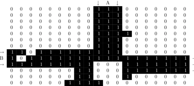
ter in which he proved that a two-state cellular automaton communicating only with its four nearest edge neighbors is computationally universal. The automaton is gov-erned by three simple rules: a “0” cell surrounded by three or four “1” cells becomes a “1”, a “1” cell which is neighbored on two adjacent sides (north and west, north and east, south and west, or south and east) by “1” cells and on the other sides by “0” cells becomes a “0”, and finally, that any other cell retains its previous value. Universality was proven largely by the implementation of a universal logic element, B∧ ¬A, shown in Fig. 2-1. Other logic elements, such as B ∧ A, can be constructed using this one and similarly sized routing and fan-out components exhibited in the Banks thesis. Despite the simplicity of each individual cell, to perform interesting computation, a large number of such cells is needed.
↓ A ↓ 0 0 0 0 0 0 0 0 0 1 1 1 0 0 0 0 0 0 0 0 0 0 0 0 0 0 0 0 1 1 1 0 0 0 0 0 0 0 0 0 0 0 0 0 0 0 0 1 1 1 0 0 0 0 0 0 0 0 0 0 0 0 0 0 0 0 1 1 1 0 0 0 0 0 0 0 0 0 0 0 0 0 0 0 0 1 1 1 1 0 0 0 0 0 0 0 0 0 0 0 0 0 0 0 1 1 1 0 0 0 0 0 0 0 0 0 0 0 0 0 0 0 0 1 1 1 0 0 0 0 0 0 0 → 1 1 0 1 1 1 1 1 1 1 1 1 0 0 0 0 0 0 0 B 1 0 1 1 1 1 1 1 1 1 1 1 1 1 1 1 1 1 1 → → 1 1 1 1 1 1 1 1 1 0 0 0 1 1 1 1 1 1 1 → 0 0 0 0 0 0 0 1 1 0 0 0 1 1 1 1 1 1 1 → 0 0 0 0 0 0 0 1 1 0 0 0 1 0 0 0 0 0 0 0 0 0 0 0 0 1 1 1 1 0 0 0 0 0 0 0 0 0
Figure 2-1: E. Roger Banks’ universal logical element (computes B ∧ ¬A). A logical T RU E is represented by a two-“0” pattern along three parallel lines of “1”s (seen here coming into input “B”).
2.2: Logic CA 21
2.2
Logic CA
2.2.1
Motivation
The original model presented in this section improves the product of complexity per cell and the number of cells needed to achieve the design by incorporating Boolean logic directly in the cells instead of deriving it from ensembles of cells. For instance, although a Banks CA cell can be implemented in about 30 transistors, implement-ing a full adder would require over 3000 Banks cells (about 90,000 total transistors). Another way of looking at this is to say that we are trading off system complexity against design complexity, but in fact, in any given application, design complexity bounds total system complexity (enough cells are needed in the system to represent the design) so both are improved in practice. Note that this does impact the theoret-ical power of the model: a consequence of Turing-universality is that any universal CA can compute an equivalent class of functions given sufficient time and storage. What we are considering here is a means to decrease the specific storage requirement for a representative problem (in this case, the simple combinatorial circuit of the full adder). We considered some different ways to achieve this, and found that a rela-tively low complexity product is attained by a CA in which each cell is essentially a processor with one one-bit register and a set of one-bit instructions, which we call the “Logic CA”. The basic concept of the Logic CA is to recognize that if making Boolean logic circuits is the goal, and if transistors (or other types of switches) are the physical substrate, then it is quite sensible to include Boolean logic functions directly in the definition of the CA. In addition, if crossovers are part of the goal, and are admissible in the substrate, then it is reasonable to allow diagonal connections between cells to cross each other. In this model, a full adder can be implemented in 6 cells, each consisting of 340 transistors, for a total of 2040 transistors, improving the complexity product by more than an order of magnitude. However, these concessions
do not only improve the numbers, but are also qualitatively beneficial for ease of design synthesis.
2.2.2
Details
The Logic CA consists of cells with 8 neighbors and 9 total bits of state. The state bits are divided into 8 configuration bits (specifying the “instruction” to be performed at every clock tick) and 1 dynamic state bit. The configuration bits are further divided into 2 gate bits which choose among the four allowed Boolean functions (G = {AND, OR, XOR, NAND}) and 6 input bits which choose among the 36 possible pairs of (potentially identical) inputs chosen from the 8 neighbors (1
2·8·(8−1)+8). At
each time step, a cell examines the dynamic state bit of its selected inputs, performs the selected Boolean operation on these inputs, and sets its own dynamic state to the result.
Mathematically, an instance of the Logic CA can be described as a series of global states St (t ∈ N0) each composed of local states st(i,j) ∈ {0, 1} (i, j ∈ Z) and a set of
constant configuration elements
c(i,j)∈ C = (G × ({−1, 0, 1}2− {(0, 0)})2)
= G × {(1, 0), (1, 1), (0, 1), (−1, 1), (−1, 0), (−1, −1), (0, −1), (1, −1)} × {(1, 0), (1, 1), (0, 1), (−1, 1), (−1, 0), (−1, −1), (0, −1), (1, −1)}
(note that there is a bijection between C and {0, 1}8, 8 bits) such that given the
definitions
g(i,j) = (c(i,j))1 ∈ G (the selected gate)
a(i,j) = (i, j) + (c(i,j))2 ∈ Z2 (the coordinates pointed to by input A)
2.2: Logic CA 23
we have the update rule:
st+1(i,j)=
if g(i,j)= AND sta(i,j) ∧ s
t b(i,j) if g(i,j)= OR st a(i,j) ∨ s t b(i,j)
if g(i,j)= XOR sta(i,j) ⊕ s
t b(i,j) if g(i,j)= NAND ¬( st a(i,j) ∧ s t b(i,j) )
This description as a formal CA is cumbersome because the Logic CA sacrifices math-ematical elegance for practical utility, but be assured that it represents the same concept as the paragraph of prose at the beginning of the section.
In pictures of the Logic CA such as Fig. 2-2, the smaller squares outside the large squares representing each cell indicate the selected input directions for a given cell, the central glyph indicates the selected Boolean function, and the color of the glyph indicates the dynamic state (the shade on the farthest left cell represents 0, and the shade on the farthest right represents 1).
2.3
Asynchronous Logic Automata
2.3.1
Motivation
There are a few driving factors that push us to consider a version of the Logic CA which is not driven by a global clock (i.e. not all cells update simultaneously). The first is simply the cost of distributing the global clock without losing phase over an indefinitely sized array. Even if it may be possible to correct phase and distribute the clock locally using a phase-lock loop [17] or similar strategies, clock distribution will still cost power. More importantly, updating all cells simultaneously wastes power since some areas of the array may have more work to do than others at any given time, and ought to be updated more because of it.
By “asynchronous” here, we do not simply mean that each element might perform its designated operation at any moment, nor do we mean that there are a few clocked elements which each have an independent clock. Rather, there are strict conditions on when operations can be performed based on data dependencies (the inputs must be ready to provide input, and the outputs must be ready to receive output). These conditions cannot be reversed except by the operation, and the operation can be delayed any amount of time without causing the overall system to have a different result (the result would simply appear later). When traditional architectures are made to run without a global clock [48], the data dependencies in these architectures can be very complex, and a huge amount of design effort is required to make sure they are always resolved. The trick here that makes asynchronous design easy is that because each individual bit is a processor, and each processor is only dealing with O(1) bits at any given time, the constraints necessary to make an asynchronous circuit work can be enforced by the substrate itself, below the level of Logic CA circuit design.
2.3: Asynchronous Logic Automata 25
lines”. These are parts of the circuit which exist solely to make the length of two con-vergent paths equal so that their signals arrive at the same time. In an asynchronous version, these become unnecessary, since the merging point will have to wait for both signals to be ready. This saves space, time, and power, and makes creating valid algorithms simpler.
Also, as we will see, the changes needed to make the Logic CA work asynchronously without explicit acknowledgment signals also make the application of charge-conserving logic possible. Traditional complementary metal-oxide-semiconductor (CMOS) logic sinks charge at every gate input and sources it again at the output, dissipating and consuming energy. Charge-conserving logic ejects the same electrons at the output as entered the input (along with some extra to restore those which left due to thermal factors). This also saves a large amount of power.
In short, power is saved by:
• not distributing a clock signal over a large physical space, • not consuming power in areas which are idle,
• and not dissipating 12CV2 with every operation.
In addition, speed is improved since cells which are only passing data from input to output, and not computing, may move data at gate propagation speed, (about 1 millimeter per nanosecond) which is a couple orders of magnitude slower than light, but a few orders of magnitude faster than a synchronous Logic CA would be.
2.3.2
Details
Asynchronous Logic Automata (ALA) are modification of the Logic CA, inspired by both lattice-gas theory [43] and Petri net theory [31], that realizes the benefits
described above.
By “lattice gas”, we mean a model similar to cellular automata in which the cells communicate by means of particles with velocity as opposed to broadcasted states. Practically, this means that the information transmitted by a cell to each of its neigh-bors is independent in a lattice gas, where in a cellular automaton these transmissions are identical. By convention, a lattice gas also has certain symmetries and conser-vation properties that intuitively approximate an ideal gas [18], and in some cases, numerically approximate an ideal gas [13].
Meanwhile, Petri nets are a broad and complex theory; we are primarily concerned with the subclass known as “marked graphs” (a detailed explanation can be found in [29]). In short, a marked graph is a graph whose edges can be occupied at any given time by zero or more tokens. According to certain conditions on the tokens in edges neighboring a node of the graph, the node may be allowed to “fire” (at any time as long as the conditions are met) by performing some operations on the tokens (such as moving a token from one of its edges to another or simply consuming a token from an edge). Petri nets have been used for the explicit construction of asynchronous circuits in the past [11, 28], but not in combination with a cellular structure.
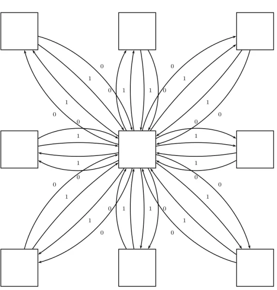
Asynchronous Logic Automata merge these with the Logic CA as follows. We remove the global clock and the bit of dynamic state in each cell, and replace the neighborhood broadcasts with a set of four edges between neighboring cells, each containing zero or one tokens, thus comprising a bit of state (see Fig. 2-3). Between each pair of cells, in each direction, we have a pair of edges, one to represent a “0” signal, and the other a “1” signal. Note that each pair of edges could be considered one edge which can carry a “0” token or a “1” token. Instead of each cell being configured to read the appropriate inputs, this data is now represented by an “active” bit in each edge. Then, each cell becomes a stateless node (except that it still maintains its own gate type) in this graph, which can fire on the conditions that all its active inputs
2.3: Asynchronous Logic Automata 27 0 1 1 0 0 1 1 0 0 1 1 0 0 1 1 0 0 1 1 0 0 1 1 0 0 1 1 0 0 1 1 0
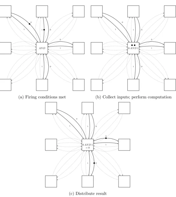
are providing either a “0” token or a “1” token and that none of its active output edges is currently occupied by a token of either type. When firing, it consumes the input tokens (removing them from the input edges), performs its configured function, and deposits the result to the appropriate output edges (see Fig. 2-4 for an example of a 2-input, 2-output AND gate firing). As it is a marked graph, the behavior of this model is well-defined even without any assumptions regarding the timing of the computations, except that each computation will fire in some finite length of time after the preconditions are met.
The model now operates asynchronously, and removes the need not only for a global clock, but any clock at all. In addition, the ”handshaking” mechanism is simply the charging of a capacitor to signal data ready (which capacitor is charged represents the value of the data) and the discharging of the same capacitor by a neighboring cell to represent data acknowledgment. As a final bonus, the charge removed from each capacitor can be placed by bucket-brigade logic [36] onto the output capacitor with minimal energy dissipation, lowering power consumption.
We have also introduced explicit accounting for the creation and destruction of tokens instead of implicitly doing both in every operation, as with traditional CMOS logic. For instance, in Fig. 2-4, since there are equally many inputs and outputs, no tokens must be created or destroyed. Only cells with more outputs than inputs must consume power, and only cells with more inputs than outputs must dissipate heat. While the model still uses the same irreversible Boolean functions, these functions can be thought of as being simulated by conservative logic which is taking in constants and dispersing garbage [12], enabling an easy pricing of the cost of non-conservatism in any given configuration.
2.3: Asynchronous Logic Automata 29 AN D 1 0 1 0 0 1 0 1
(a) Firing conditions met
0 AN D 1 1 0 1 0 0 1 0 1
(b) Collect inputs; perform computation
0 AN D 1 = 0 1 0 1 0 0 1 0 1 (c) Distribute result
Figure 2-4: An ALA cell firing; note that despite the loss of information (the inputs are not deducible from the outputs), tokens are conserved in this example
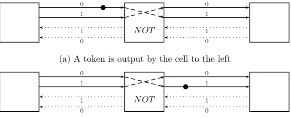
In addition, this model adapts much more easily to take advantage of adiabatic logic design. For instance, when a cell is being used only to ferry tokens from one place to another (e.g. an inverter, shown in Fig. 2-5), it can do so physically, instead of using a traditional, charge-dumping CMOS stage.
0 1 1 0 N OT 0 1 1 0
(a) A token is output by the cell to the left
0 1 1 0 N OT 0 1 1 0
(b) The token now passes to the right cell
Figure 2-5: A bit travels left to right through an inverting cell
Note the following possible ALA variations:
1. No Diagonals. Connections may only be present between vertically or horizon-tally adjacent cells, to simplify hardware layout.
2. Alternate Lattices. Indeed, any regular connection topology may be used, including alternate two-dimensional layouts such as hexagonal lattices or even three-dimensional structures such as the body-centered cubic lattice.
3. More Functions. The class of possible functions executed by each cell need not be limited to {AND, OR, XOR, NAND} but may include any function f : {0, 1, ∅}n→ {0, 1, ∅}n(mapping from possible input states to possible output
actions) where n is the number of neighbors of each cell. For n = 4, there are about 1061functions on a fixed number of inputs; for n = 6, there are about
10687. A cell executing function f may fire if f ’s present output is not ∅n (i.e. if
2.3: Asynchronous Logic Automata 31
the output points to either an inactive or empty set of output edges. Then each of those output edges would become populated with the value specified by f’s output. There is a tradeoff between the number of functions allowed and the number of configuration bits in each cell needed to specify the function.
4. Multiple Signals. More than four token-storing edges may connect neighbor-ing cells, allowneighbor-ing the conveyance of more parallel information in the same period of time. This could be used for special programming inputs, or for gates which act bitwise on multiple bits.
2.3.3
ALA Simulator
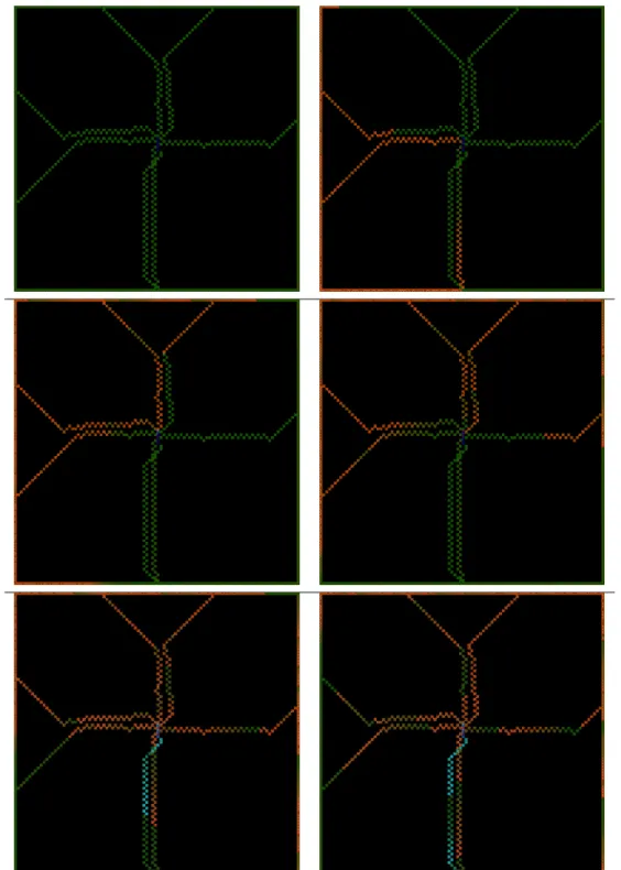
We wrote a simulator for Asynchronous Logic Automata using the C language, Guile (an embeddable Scheme interpreter), OpenGL, and freeglut. The code is listed in Appendix A. The high-level algorithm is to keep a list of cells whose firing conditions are met, and choose a random one to fire at every time step. The description of the configuration to simulate is generated at run-time by a Scheme program provided as input. Some examples of input code can be found in Appendix B. Figure 2-6 is a montage showing the first few frames of output from the circuit described by lfsr.scm (section B.2). The visualization used by the ALA simulator is different to that of the Logic CA: gate type is represented by color, and bits traveling through the gates have fading trails through these gates. This reflects where computation is happening (and where power is being dissipated).
Chapter 3
Algorithms
3.1
SEA Implementation
3.1.1
Motivation
One application that is particularly well-suited to implementation in a model such as this is symmetric encryption as a Feistel cipher. Because these cipher structures can operate on streams, they can take advantage of an arbitrary degree of parallelism to deliver a corresponding degree of security, and because Feistel ciphers are typically expressed as dataflow diagrams, it is natural to express the algorithm in the form of a fixed picture that data flows through – the easiest way to program the logic CA.
In the space of Feistel ciphers, with a context in which resources are priced at fine granularity, it is natural to choose a minimalistic Feistel cipher which provides all the desired security properties such as diffusion and resistance to linear and differential cryptanalysis while requiring the least computation. This is the role filled by SEA: a Scalable Encryption Algorithm for Small Embedded Applications [39].
3.1.2
SEA Components
SEA assumes very little computing power from its host. The primitive operations used to construct the Feistel functions are:
1. Bitwise XOR
2. Substitution box composed from AND, OR, and XOR 3. Word rotate
4. Bit rotate 5. Addition
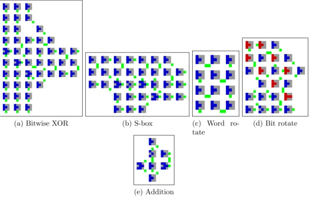
Each of these components has been implemented using the synchronous Logic CA model, as seen in Fig. 3-1. Note that computation proceeds from right to left and bottom to top in these figures.
Since XOR is a primitive function of the CA cell, bitwise XOR over 3 simultaneous streams is largely an exercise in routing and timing, with the computation taking place in the center (Fig. 3-1a). The substitution box (s-box, Figure 3-1b) is simply implemented as it is described in the SEA paper (with some extra cells to ensure timing uniformity in the Logic CA):
x0 = (x2∧ x1) ⊕ x0
x1 = (x2∧ x0) ⊕ x1
x2 = (x0∨ x1) ⊕ x2
As shown, x0 is on the bottom. Word rotate (Fig. 3-1c) is a series of four swaps which
3.1: SEA Implementation 35
carefully timed delay circuit which extracts the last bit of each byte and delays it until the end of the byte. The addition block (Fig. 3-1e) is actually the simplest of these circuits – it need only keep track of the carry bit and execute a full add every time step.
(a) Bitwise XOR (b) S-box (c) Word
ro-tate
(d) Bit rotate
(e) Addition
Figure 3-1: Components of SEA implemented in the Logic CA
3.1.3
Complete Round
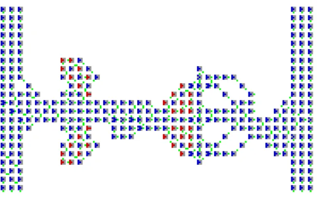
Given these primitives, an encryption round of SEA can be constructed as seen in Fig. 3-2. The two inputs are at the bottom edge on either side. The right-hand block is passed through an adder (which would be connected in the context of the full cryptosystem to a key generation round which looks much the same), then left to the S-box, then two of the three words are bit-rotated, and finally the result is XORed with the word-rotated left-hand block to produce what will be the right-hand block in the next round (in the context of the full cryptosystem, sequential rounds are followed by a crossover). Note that the right-hand block must arrive in advance of the
left-hand block in this model, since it must pass through the horizontal section before meeting the left-hand block at the XOR. By assembling this building block into the appropriately sized structure, we can obtain any desired degree of cryptographic confusion and diffusion, with no cost to continuous throughput (only latency).
Figure 3-2: A single round of SEA built from primitives
3.1.4
Encrypt-Decrypt
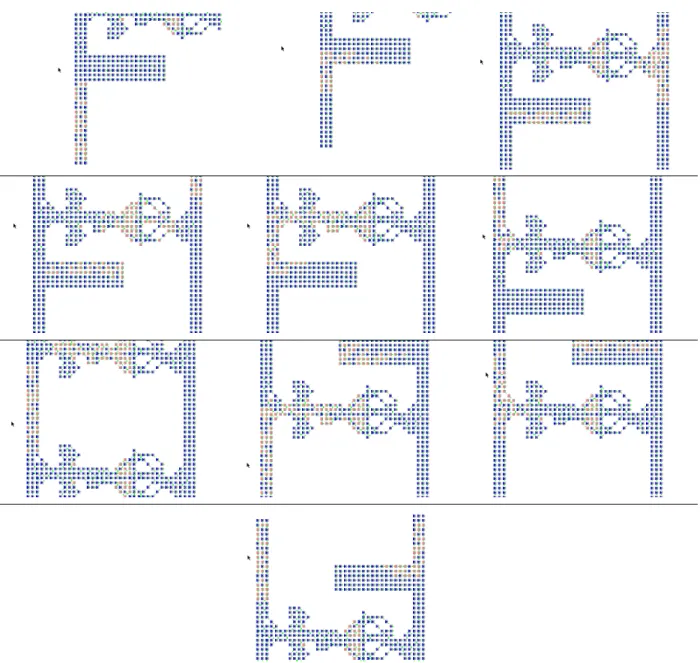
Fig. 3-3 is a montage showing what happens when we feed the letters “CBA” through one encryption round and one decryption round of SEA. It should be read from left to right and then from top to bottom. In the first frame, you can see the vertically stacked letters on the left side, then you can follow the bits as they are delayed while the meaningless right-hand block is passing through the horizontal elements. In the fifth frame, the blocks meet at the XOR junction. The seventh frame shows the “encrypted” data in full between the encrypt round and the decrypt round. In the
3.1: SEA Implementation 37
eighth frame, this data is re-XORed with the same key, regenerated by the machinery of the decrypt round, and word-rotated in the inverse direction. In the final frame, we can see that the letters “CBA” have once again emerged.
Figure 3-3: An encrypt round and a decrypt round of SEA passing the information “CBA”.
3.2
Bubble Sort Implementation
3.2.1
Overview
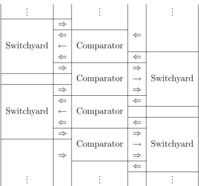
“Bubble sort” is a simple, classic sort algorithm which can be described as repeatedly checking each neighboring pair of elements and swapping them if they are out of order [21]. It is so called because elements which are out of place will gradually “bubble” up to their sorted location through a series of nearest-neighbor transpositions. On sequential computers, the checks must be performed one at a time, meaning that a sequence of O(n2) operations (one check/swap each) is needed to guarantee that the entire set has been sorted. Thus bubble sort is typically ignored in favor of algorithms such as quicksort, which can sort with only O(n lg n) operations. On a cellular com-puter, checks of non-overlapping pairs of elements can be performed simultaneously at no extra cost, so O(n) operations (each comprising O(n) checks) are sufficient – fewer than the best possible sequential algorithm. Note that with denser interconnection topologies, such as shuffle-exchange or hypercube, only O(lg2n) operations may be needed [7], but with only local connections, O(n) operations is provably optimal [6]. The CA implementation of bubble sort is made from two main components, which we call the “switchyard” and the “comparator”. Fig. 3-4 shows how these components interact. Note that this scheme can be viewed as a compromise between the sequential bubble sort algorithm and the “diamond” sorting network of Kautz [20], which is in turn equivalent to the odd-even transposition sorting network [22, 35]. Each comparator operates on two binary strings (elements to be sorted) and outputs them unmodified, along with a single-bit control line which indicates whether the elements are out of order. If so, the corresponding switchyard transposes them; otherwise, it also passes them back out unmodified for the next round of comparisons. Half the comparators or half the switchyards are active at any given time step (necessary since all the pairs being compared simultaneously are non-overlapping).
3.2: Bubble Sort Implementation 39 .. . ... ... Switchyard ⇒ ⇐ Comparator ⇐ ← ⇐ ⇐ Switchyard ⇒ Comparator ⇒ → Switchyard ⇒ ⇒ ⇐ Comparator ⇐ ← ⇐ ⇐ Switchyard ⇒ Comparator ⇒ → ⇒ ⇒ ⇐ ... ... ...
Figure 3-4: Block-level architecture of bubble sort in the Logic CA
3.2.2
Sort Components
Fig. 3-5 shows a left-side switchyard and comparator implemented in the synchronous Logic CA, oriented the same way as the topmost switchyard and comparator in Fig. 3-4. The inputs of the switchyard are on the right-hand side in the vertical center, with the control line being between the binary string inputs. The outputs of the switchyard are on the right-hand side at the vertical extremes. The inputs of the comparator are on the right, and the outputs on the left (with the control line in the vertical center). The switchyard (Fig. 3-5a) includes very little logic; it is mostly wires (chains of AND gates whose inputs are both tied to the last). These paths extend from both inputs to both outputs (four in all), and the control paths extend from the control input to both corners (where the NAND gates are). The paths which cross in the middle are only enabled when the control line is on (they are ANDed with it), and the paths which are aligned with the top and bottom edges are only enabled when the control input is off (they are ANDed with the NAND of the control line). The paths are merged at the
outputs using OR gates.
(a) Switchyard (b) Comparator
Figure 3-5: Components of sort implemented in the Logic CA
The comparator (Fig. 3-5b) also includes long data paths, which can be traced along most of the top and bottom edges, but unlike the switchyard, contains significant logic and state in the center. At the right edge are detectors for bit mismatches in the input, which are inputs to two OR-based bit stretchers that stabilize NAND-NAND flip-flops which compute the output and latch it on the control line. A reset input, intended to connect to a timer depending on the length of strings being sorted, can be seen coming down from the top, toward the left-hand side.
3.2.3
Complete Sort
We can flip and assemble these elements, given the pattern in Fig. 3-4, into a CA like Fig. 3-6. In order to match up the vertical locations of inputs and outputs in the comparator and switchyard, vertical wires are added where needed.
3.2: Bubble Sort Implementation 41
Chapter 4
Ongoing and Future Work
4.1
Conformal Computing Team
This work was done in the context of the Conformal Computing project, a project to develop computers that:
• cover surfaces and fill volumes • are incrementally extensible
• have embedded, unobtrusive form factors
• solve distributed problems with distributed solutions • adapt to applications and workloads
• operate reliably from unreliable parts
This project is a collaboration between the Massachusetts Institute of Technology Center for Bits and Atoms and the North Dakota State University Center for Nanoscale
Science and Engineering. The Conformal Computing team includes Kailiang Chen, Kenny Cheung, David Dalrymple, Ahana Ghosh, Forrest Green, Mike Hennebry, Mariam Hoseini, Scott Kirkpatrick, Ara Knaian, Luis Lafeunte Molinero, Ivan Lima, Mark Pavicic, Danielle Thompson, and Chao You. Work being done in this project fills in the lower and higher level components necessary to turn the concepts in this thesis into a complete system:
• Programming Models
– Hierarchical Design Tool and – Mathematical Programming • Cellular Microcode
– Logic CA or
– ALA, possibly with – Coded Folding, – Scale-Invariance, and – Fault Tolerance • Hardware Realizations – CA Strips, – CA ASIC, and – Molecular Logic [2, 9, 42]
4.2
Programming Models
The primary disadvantage to practical fabrication and use of ALA in their present form is the need to simultaneously initialize all cells with the configuration data
4.3: Model Improvements 45
before useful computation can be performed, as well as the lack of special-purpose tools for generating this data.
4.2.1
Hierarchical Design Tool
Forrest Green is working on a design tool for the Logic CA and ALA that uses ”li-braries” of small hand-coded primitives for operations such as adding and comparing, and allows the composition of new, more complex primitives using a path-finding algo-rithm to connect input and output ports. This tool would have the appearance of a vi-sual dataflow programming language like Max/MSP, Labview, or Simulink, but the picture would actually represent a directly executable plane of CA configuration data.
4.2.2
Mathematical Programming
Scott Kirkpatrick and Luis Lafuente Molinero are working on the theory of gen-erating ALA patterns as the result of an optimization problem. For instance, the sort described in section 3.2 can be derived as the optimal searcher through the space of permutations described as products of primitive transpositions. In ad-dition, they are developing an optimization solver which will run in software on the ALA, and fully solve certain classes of mathematical programs in general.
4.3
Model Improvements
4.3.1
Coded Folding
Erik Demaine and Kenny Cheung are helping to develop a protocol for loading configuration data in with a communication channel to exactly one cell, by com-puting a Hamiltonian path which contains all the cells to be programmed, and
informing each cell, after it is configured, in which direction it should forward the rest of the data stream, then finally propagating a signal to begin the computation. We are also considering similarities between ALA and von Neumann’s original self-reproduction automaton [46] and are exploring ways to make the von Neumann automaton asynchronous and easier to design in.
4.3.2
Scale-Invariance
ALA are translation-invariant: moving a boundless, unprogrammed ALA any num-ber of cells in any direction does not change it. This is particularly useful for problems with a naturally translational structure: sorting flat lists, processing streams, simulat-ing locally interactsimulat-ing elements in space, etc. However, many types of problems are naturally scale-invariant (i.e. they contain structures similar to their own), such as parsing markup languages or complex recursive algorithms. These prob-lems, when embedded in Euclidean space, require direct, high-speed interactions between relatively distant elements, since the number of elements reachable through n scaling steps of k scale factor grows as kn, while the number of elements reachable
through n translations in k dimensions grows as nk, and kn ≫ nk as n → ∞.
Even though the ALA can propagate signals along fixed paths fairly quickly, we ex-pect that with hardware available today, this speed would come at best within two orders of magnitude of the speed of light, and this cost will accumulate for scale-invariant sorts of problems. This suggests that a reasonable (though significant) modification to the ALA concept would be to add a hard-wired, scale-invariant overlay which helps speed up this type of problem.
4.4: Hardware Realizations 47
4.3.3
Fault Tolerance
Although error correction can implemented in ALA software using redundant wires and majority voting [45], we are exploring various ways to make the model itself tol-erant of faults in the underlying hardware. This may take the form of an arm searching for defects and designing around them [24], or cells which implement a code internally [30]. Both methods may also be helpful, since some hardware defects are per-manent as a result of fabrication errors, while others are transient as a result of ther-mal noise or other factors disturbing an element which is otherwise in specification.
4.4
Hardware Realizations
4.4.1
CA Strips
Mike Pavicic, Michael Hennebry, and their team at the Center for Nanoscale Sci-ence and Engineering and North Dakota State University (NDSU) have created a hardware platform (Fig. 4-1) based on an 8x8 array of ATMega168 AVR pro-cessors, with a 32x32 array of color LEDs on the opposite face, which implements a Logic CA simulator. This substrate is actually composed of 8 “strips” each with 8 pro-cessors, and can be indefinitely extended in one direction. They are working towards processes which are indefinitely extensible in two directions, and eventually three.
(a) One side of the strips is an 8x8 array of AVR processors
(b) The other side is a 32x32 array of color LEDs
4.4: Hardware Realizations 49
4.4.2
CA ASIC
Chao You (also at NDSU) has designed a silicon layout for a Logic CA (Fig. 4-2) and Kailiang Chen (MIT) has fabricated an analog logic version of the Logic CA (Fig. 4-3) and is working on a silicon layout for an ALA.
4.4: Hardware Realizations 51
4.4.3
Molecular Logic
We are also looking ahead toward direct-write nanostructures working with Joe Jacobson’s group, which have demonstrated the fabrication of nanowire transistors [2], and toward other types of molecular logic such as that being developed at Hewlett-Packard Laboratories [9, 42].
4.5
Applications
Increasingly, computer graphics performance is improved mainly by adding pixel pipelines, but consider the possibility that every single pixel can be processed in paral-lel. We are examining 2D and 3D graphics applications in which sites at regular in-tervals on a planar array or one face of a spatial array corresponds to a light-emitting element, and the computation of pixel values takes place in a spatially distributed, concurrent way. For 3D graphics we may even imagine a raytracer operat-ing by actually firoperat-ing rays as propagatoperat-ing signals through the volume of the de-vice. In addition, we are considering the case that these special sites on the surface cor-respond to photodetectors, or even that both types of sites are present, and us-ing clever optical filterus-ing to make an indefinitely high-resolution camera, or to make an indefinitely large multi-touch display.
Meanwhile, high-performance computing is limited by the power consumption of the largest computers, but also by the ability to program them. We have also had sub-stantial interest from the high-performance computing community, not just about using physical ALA to solve scientific problems, but even to use the ALA programming model as a way to program existing supercomputers. By implementing an extremely well-optimized ALA simulator, the ALA software running on top of it need not take the standard considerations that make developing sequential software for su-percomputers so difficult. In addition, the flexibility of ALA architectures allow for in-definite fixed-precision numbers, removing floating-point roundoff as a common source of scientific computing bugs. Implementing a high-performance computer using ALA as the physical substrate would provide all these benefits in addition to saving power. Finally, we are looking forward to using the ALA to implement Marvin Minsky’s Emo-tion Machine architecture [27], which requires numerous agents acting concurrently as well as a hierarchy of critics which determine which agents ought to be en-abled at any given time. The massive, but non-uniform, parallelism of the Emotion
4.5: Applications 53
Machine fits neatly onto ALA (which are also non-uniform and massively parallel). Al-though this architecture would be a useful one for the development of ALA software in any case, it is supposed that this could lead to a machine which displays some characteristics of intelligence.
Chapter 5
Concluding Remarks
Computer science as an industry, and to some extent as a field of study, was derailed by a series of unfortunate events that led to von Neumann’s EDVAC [47], a machine made to do arithmetic in a flexible way, being the ancestor of all modern com-puter designs. The first microprocessor, Intel’s 4004, was built using this archi-tecture because it was designed for a high-end desk calculator. Unfortunately, the con-cept of the microprocessor has been tied to this architecture ever since, despite the best efforts of academics and venture capitalists alike, leading to much pain for programmers, who pass much of it on to the end user through unreliable software. However, this type of machine will soon finally reach the point in its evolution at which it is no longer even “good enough” for the constantly rising performance that industry expects and demands. This is a golden opportunity for a brand of “fundamen-talist” computer science: we can revisit the final (rather than the earlier, mis-understood, and hopelessly popular) wisdom of von Neumann [46] and Backus [4], and give credence to all the great ideas from over 20 years ago (including but hardly limited to [19, 12, 24, 11, 20]) that have been ignored by the mainstream establishment. Fun-damentalist computer science is also funFun-damentalist in that we are interested in the fundamentals of computing. This may sound like a vacuous statement, but there is
far too little attention given today to the theory of how real-world physics can best support reliable, controlled computations of arbitrary size and complexity.
In a world where computers are not so distanced from physics, they will be far more intuitive to work with and program, since humans are very comfortable with items that have a size, location, speed, and other well-defined properties. We call these things “concrete”, although they may in fact be abstract concepts in our minds, be-cause they can be thought of in the physical framework all people need to deal with the world we live in. In a modern computer program, variables are omnipresent, and ma-terialize wherever they are summoned by name, while statements exist only one at a time, in an order that is not even possible (in general) to determine in advance. These concepts are plainly impossible physically, so we simulate them by using random-access memories and program counters. These concepts are all well and good, but should be chosen, rather than imposed. For instance, when so-called “object-oriented programming” is employed, the computer is required to do extra work to ensure that certain variables are only accessible within a restricted domain, while from a physical perspective, such a restriction ought to make the computer’s work much lighter, since it would no longer need to deliver variables between distant objects while keeping their values consistent. The hiding of physics behind an over-generalized model of computation introduces an exaggerated tradeoff between “programmer time” and “computer time”. Would you rather take full advantage of the computer’s forced non-physicality, but be burdened in your programming by the non-intuitiveness of non-physicality; or would you rather program in an intuitive way (by encapsulating variables in objects and composing transforming functions with each other) but pay the price of having these more physically constrained ideas simulated by a non-physical model that is in turn being simulated by physics itself, causing program speed to suffer? Programming in an intuitive way ought to result in faster pro-grams, because physical constraints are recognized to a greater extent.
57
In addition, the design, construction, and configuration of systems which are phys-ically large or sparse should become far easier, because the size or sparsity (and the as-sociated restrictions on state mixing) could be represented automatically in the pro-gramming model. No longer must such systems be subdivided into “nodes” – domains within which engineers were successfully able to circumvent physics without too much cost, and outside of which, there exist few principled ways to construct programs. In-stead, by exposing the physical constraints within the programming models, these sys-tems can be exploited fully without any distinguished programming techniques. We can imagine a world [16, 23] which is filled with computing devices, which are not so much hidden as transparent. This computation can be put to use for everything from managing the energy use of buildings, to distributed videoconferencing in which network routing is derived as an optimization constrained by physics rather than as ad-hoc algorithms, to simulating human brains. All this computing can be made far easier to use, to the extent that the distinction between users and programmers will become blurred. Due to the less profound boundaries between the inside and outside of an individual “computer”, it can be made available much more flexibly. Of course, these ideas have a long lineage, but we believe that the need and the means to make it happen are present (or at worst, imminent). More than the final vision or the specific details, the overall message to take away is that we are likely on the verge of a paradigm shift since von Neumann’s EDVAC architecture is no longer working for many industry applications, and that making the physics of computing transparent instead of hidden is a good way to proceed. On a lower level, the author has shown that the problem of synchronicity can be addressed by making the individual bits each their own processor which can enforce data dependencies, and that dividing space into a regular lattice of similar processing elements at the granularity of one bit is a simple yet effective way of representing the speed of light and density constraints of physics. This work is a small but important step toward the computers of the future.
Appendix A
ALA Simulator Code
A.1
ca.c
1 # include < stdlib .h > 2 # include < stdio .h > 3 # include < string .h > 4 # define CELL_OUTPU T S 8 56 long int cell_fade = 1000000;
7 unsigned int shuffle_mi x = 1000;
8
9 struct ca_cell {
10 char drawable ;
11 struct ca_cell * input_a ;
12 struct ca_cell * input_b ;
13 struct ca_cell * outputs [ CELL_OUTP UT S ];
14 int output_cou n t ; 15 int i n p u t _ a _ o u t p u t _ i d x ; 16 int i n p u t _ b _ o u t p u t _ i d x ; 17 char function ; 18 char i n p u t _ a _ s t a t e ; 19 char i n p u t _ b _ s t a t e ; 20 long int l a t e s t _ u p d a t e ; 21 char latest_bit ; 22 int order_index ; 23 int d r a w _ o r d e r _ i n d e x ; 59
24 };
25
26 struct ca_canvas {
27 unsigned int width ;
28 unsigned int height ;
29 struct ca_cell * cells ;
30 int * update_or de r ;
31 int ready_cells ;
32 int * draw_order ;
33 int d r a w a b l e _ c e l l s ;
34 unsigned long int ca_time ;
35 };
36
37 char ca_and ( char a , char b ) {
38 return a & b & 1;
39 }
40 char ca_or ( char a , char b ) {
41 return ( a | b ) & 1;
42 }
43 char ca_xor ( char a , char b ) {
44 return ( a ^ b ) & 1;
45 }
46 char ca_nand ( char a , char b ) {
47 return ~( a & b ) &1;
48 }
49
50 typedef char (* ca_operat i on ) ( char , char ) ;
51
52 static ca_operat io n ca_functio n s [4] = {& ca_and , & ca_or , & ca_xor , & ca_nand };
53
54 int c a _ c e l l _ c h e c k _ c o n d i t i o n s ( struct ca_cell * cell ) {
55 if (!(( cell - > i n p u t _ a _ s t a t e & 2) && ( cell - > i n p u t _ b _ s t a t e & 2) ) ) return 0;
56 int i ;
57 for ( i =0; i < cell - > output_co u nt ; i ++) {
58 if ( cell - > outputs [ i ] - > input_a == cell ) {
59 if ( cell - > outputs [ i ] - > i n p u t _ a _ s t a t e & 2) return 0;
60 } else if ( cell - > outputs [ i ] - > input_b == cell ) {
61 if ( cell - > outputs [ i ] - > i n p u t _ b _ s t a t e & 2) return 0;
62 }
A.1: ca.c 61
64 return 1;
65 }
66
67 int c a _ c e l l _ u p d a t e ( struct ca_cell * cell ) {
68 if ( c a _ c e l l _ c h e c k _ c o n d i t i o n s ( cell ) ) {
69 char n e w _ o u t p u t _ s t a t e ;
70 int i ;
71 n e w _ o u t p u t _ s t a t e = 2 | ca_functio n s [( int ) cell - >
function ]( cell - > input_a_state , cell - > i n p u t _ b _ s t a t e ) ;
72 cell - > latest_bit = n e w _ o u t p u t _ s t a t e & 1;
73 # ifdef CA_DEBUG
74 printf ( " cell updated recently , output % d \ n " , n e w _ o u t p u t _ s t a t e ) ;
75 # endif
76 cell - > i n p u t _ a _ s t a t e = 0;
77 cell - > i n p u t _ b _ s t a t e = 0;
78 for ( i =0; i < CELL_OUTP U TS ; i ++) {
79 if ( cell - > outputs [ i ]!= NULL ) {
80 if ( cell - > outputs [ i ] - > input_a == cell ) {
81 cell - > outputs [ i ] - > i n p u t _ a _ s t a t e = n e w _ o u t p u t _ s t a t e ;
82 }
83 if ( cell - > outputs [ i ] - > input_b == cell ) {
84 cell - > outputs [ i ] - > i n p u t _ b _ s t a t e = n e w _ o u t p u t _ s t a t e ; 85 } 86 } 87 } 88 return 0; 89 } else { 90 return 1; 91 } 92 } 93
94 void c a _ c a n v a s _ s w a p ( struct ca_canvas * canvas , int n , int k ) {
95 int temp ;
96 temp = canvas - > update_or d er [ n ];
97 canvas - > update_ord e r [ n ] = canvas - > update_or de r [ k ];
98 canvas - > update_ord e r [ k ] = temp ;
99 canvas - > cells [ canvas - > update_or de r [ k ]]. order_index =k ;
101 }
102
103 void c a _ c a n v a s _ s h u f f l e ( struct ca_canvas * canvas ) {
104 int n ;
105 if ( shuffle_mi x ==0) { return ;} else if ( shuffle_mi x ==1000) { n = canvas - > ready_cells ;} else {
106 n = (( double ) shuffle_mi x ) /1000*(( double ) canvas - > ready_cell s ) ;}
107 if (n > canvas - > width * canvas - > height ) n = canvas - > width * canvas - > height ; 108 while ( n > 1) { 109 int k = rand () % n ; 110 n - -; 111 c a _ c a n v a s _ s w a p ( canvas , n , k ) ; 112 } 113 } 114
115 void c a _ c a n v a s _ u p d a t e ( struct ca_canvas * canvas ) {
116 int k ;
117 struct ca_cell * updated_ce l l = NULL ;
118 for ( k =0; k < canvas - > ready_cell s ; k ++) {
119 int i = canvas - > update_ord e r [ k ];
120 if ( canvas - > cells [ i ]. drawable ) {
121 if (!( updated_c el l || c a _ c e l l _ u p d a t e (& canvas - > cells [ i ]) ) ) {
122 updated_ce l l =&( canvas - > cells [ i ]) ;
123 canvas - > cells [ i ]. l a t e s t _ u p d a t e = canvas - > ca_time ;
124 } else if (! c a _ c e l l _ c h e c k _ c o n d i t i o n s (& canvas - > cells [ i ]) ) {
125 canvas - > ready_cells - -;
126 c a _ c a n v a s _ s w a p ( canvas , canvas - > ready_cells , canvas - > cells [ i ]. order_inde x ) ;
127 }
128 } else {
129 canvas - > ready_cells - -;
130 c a _ c a n v a s _ s w a p ( canvas , canvas - > ready_cells , canvas - > cells [ i ]. order_inde x ) ;
131 }
132 }
133 if ( updated_c el l ) {
134 int i ;
A.1: ca.c 63
136 canvas - > ready_cells - -;
137 c a _ c a n v a s _ s w a p ( canvas , canvas - > ready_cells , updated_cell - > order_index ) ;
138 }
139 for ( i =0; i < CELL_OUTP U TS ; i ++) {
140 if ( updated_cell - > outputs [ i ]!= NULL ) {
141 if ( updated_cell - > outputs [ i ] - > input_a == updated_ce l l ) {
142 if ( updated_cell - > outputs [ i ] - > order_index >= canvas - > ready_cells ) {
143 if ( c a _ c e l l _ c h e c k _ c o n d i t i o n s ( updated_cell - > outputs [ i ]) ) {
144 canvas - > ready_cells ++;
145 c a _ c a n v a s _ s w a p ( canvas , canvas - > ready_cells -1 , updated_cell - > outputs [ i ] - > order_inde x ) ;
146 }
147 }
148 }
149 if ( updated_cell - > outputs [ i ] - > input_b == updated_ce l l ) {
150 if ( updated_cell - > outputs [ i ] - > order_index >= canvas - > ready_cells ) {
151 if ( c a _ c e l l _ c h e c k _ c o n d i t i o n s ( updated_cell - > outputs [ i ]) ) {
152 canvas - > ready_cells ++;
153 c a _ c a n v a s _ s w a p ( canvas , canvas - > ready_cells -1 , updated_cell - > outputs [ i ] - > order_inde x ) ; 154 } 155 } 156 } 157 } 158 }
159 if ( updated_cell - > input_a - > order_index >= canvas - > ready_cells ) {
160 if ( c a _ c e l l _ c h e c k _ c o n d i t i o n s ( updated_cell - > input_a ) ) {
161 canvas - > ready_cells ++;
162 c a _ c a n v a s _ s w a p ( canvas , canvas - > ready_cells -1 , updated_cell - > input_a - > order_index ) ;