DYNAMIC ANALYSIS OF HIGHWAY BRIDGES UNDER
MULTIPLE RANDOM EXCITATIONS
ﻲﻤﻠﻌﻟﺍ ﺚﺤﺒﻟﺍﻭ ﻲﻟﺎﻌﻟﺍ ﻢﻴﻠﻌﺘﻟﺍ ﺓﺭﺍﺯﻭ
Minstry of Higher Education and Scientific Research
ﻡﻧﺎﻐﺗﺳﻣ ﺱﻳﺩﺎﺑ ﻥﺑﺍ ﺩﻳﻣﺣﻟﺍﺩﺑﻋ ﺔﻌﻣﺎﺟ
Abdelhamid Ibn Badis University of Mostaganem
ﺎﻳﺟﻭﻟﻭﻧﻛﺗﻟﺍ ﻭ ﻡﻭﻠﻌﻟﺍ ﺔﻳﻠﻛ
Faculty of Sciences and Technology
Order N° : D
…………/GC/2015
Thesis Submitted for
DEGREE OF DOCTOR (LMD)
Section: Civil Engineering
Option: Structures & Transportation
Presented by:
ZELLAT Kaoutar
Presented on: 02/ 06 / 2016 Before a Jury Composed of :
President: Pr. BENDANI KARIM (UMAB Mostaganem)
Examiner: Pr. BRANCI TAIEB (UHBB Chlef)
Examiner: Pr. KASSOUL AMAR (UHBB Chlef)
Supervisor: Pr. KADRI Tahar (UMAB Mostaganem)
i
Dedication
To my family
ii
Acknowledgements
This project would not have been possible without the help of Allah, the Most Gracious and the Most Merciful. Then, I would like to gratefully acknowledge the enthusiastic supervision of Pr. KADRI Tahar during the course of research for his support and guidance. He was abundantly helpful and offered invaluable assistance. Deepest gratitude go also to the members of the jury who accept kindly to read this work. I owe an enormous debt of gratitude to Pr. GENEŞ Cemal from the Zirve University (Gazientep, Turkey) for his very helpful contribution.
Special thanks to my friends for sharing literature and information. I would like also to convey thanks to all the members of the administration in the department of Civil Engineering , Sciences and Technology Faculty (Abelhamid Ibn Badis University, Mostaganem), especially Mr. BOUHALOUFA Ahmad for facilitating all the procedures of subscriptions, viva organization and dissertation submission. I thank also Dr. ZELLAT Imen for her assistance and rectifications of English language, she supplied my thesis with. In addition to the librarians for authorizing all the post grades to consult books in the library at all moment. I wish to express my love and gratitude to my beloved parents and dear family for their understanding and endless love.
iii
Abstract
Many long-span bridges throughout the world are subject to very complicated loading, especially those that are located in wind-prone regions or high seismic zones and that carry both trains and road vehicles. Taking into consideration the multiple types of loading that are concerned and the complexity of the loading combinations, the response analysis of long-span bridges under vehicle, wind loading and seismic forces stand as a great scientific challenge. Moreover, mitigation of the studied vibrations generated by those dynamic loads is of more concern because of their several consequences on the construction components safety.
This thesis focuses on the bridge vibrations and their mitigation under multiple dynamic loads to be: the vehicles, wind and earthquake. The work was divided into two parts; the first was an analytical study of separated coupled systems which are: the bridge-vehicle, the wind-bridge-vehicle and the bridge-seismic with a numerical simulation for each one. In the second part a comparison study was developed between a bridge structure provided by vibrations mitigation mechanism and the same structure without vibrations absorbers under a strong earthquake.
The bridge-vehicle system was modelled as two separated three dimensional subsystems, the equations of motion were established for each model and the interacting forces were determined by the method of moments. A numerical simulation was given to illustrate the analysis using SAP2000 V 16 structural software applied on a cable stayed bridge.
The effect of aerodynamic loads applied on the bridge-vehicle coupled system was studied as a second step, the equations of motion of the three dimensional models were extracted and wind forces acting on the bridge and the vehicle were simulated using analytical approaches. To investigate the dynamic response of the vehicle-bridge system under wind actions an incremental-iterative approach was
iv
used where the nonlinear aerodynamic curves were simulated by a sequence of piecewise connected linearly.
Seismic forces present the most critical loads applied on bridge structure, for that reason, the comparative study on isolated bridges was against earthquake excitation. The study put most emphasis on the time variation of base shear and bearing displacement in order to understand the behaviour of seismically isolated bridges with a comparison between isolated and non isolated bridges. For this purpose seismic forces were applied as a spectrum obtained from recorded strong earthquakes by specialized stations on the three dimensional bridge model using structural software. Three kinds of bearings were studied including N-Z, LRB and FPS since they are considered as the most popular bearings in the field of bridges vibration control.
v
Résumé
De nombreux ponts à longue travée à travers le monde sont soumis à des chargements très compliqués, en particulier ceux qui sont situés dans les régions menacées par les tourbillons de vent ou zones à séismicité élevée et aussi qui transportent des trains et des véhicules en même temps. Compte tenu des multiples types de chargements concernés et la complexité des combinaisons de chargement, l'analyse de la réponse des ponts à longue travée sous l’effet des véhicules, du vent et des forces sismiques est un grand défi scientifique.En outre, l'atténuation des vibrations étudiées et qui sont générées par ces charges dynamiques est plus pertinente vue leurs nombreuses conséquences néfastes sur la sécurité des éléments de la construction pont.
Cette thèse porte sur les vibrations de la structure pont et leur atténuation dans la présence des charges dynamiques multiples; soit les véhicules, le vent et les tremblements de terre. Le travail a été divisé en deux parties dont la première était une étude analytique des systèmes couplés séparément soient pont-véhicule, vent-pont-véhicule et pont-séisme avec une simulation numérique pour chacun d'eux. Dans la deuxième partie une étude comparative a été établie entre une structure pont munie d’un mécanisme d'atténuation des vibrations et la même structure sans absorbeurs de vibrations sous l’action d’un tremblement de terre.
Le système pont-véhicule a été modélisé comme deux sous-systèmes tridimensionnels séparés, les équations du mouvement ont été établies pour chaque modèle et les forces d'interaction ont été déterminées par la méthode des moments. Une simulation numérique a été établie pour illustrer l'analyse en utilisant le logiciel structurel SAP2000 V 16 appliquée sur un pont à haubans. L’effet des charges aérodynamiques sur le système couplé pont-véhicule a été étudié dans une deuxième étape, les équations du mouvement des modèles tridimensionnels ont été extraites et les forces du ventappliquées sur le pont et le véhicule ont été simulées à l'aide des approches analytiques. Afin d’analyser la réponse dynamique du système véhicule-pont sous l’action du vent une approche
vi
itérative incrémentale a été utilisée là où les courbes aérodynamiques non linéaires ont été simulées par une séquence de morceaux reliés linéairement.
Les forces sismiques présentent les charges les plus critiques appliquées sur la structure pont, en fonction de cette raison que l'étude comparative sur l’isolation des ponts était sous l’effet de l’excitation de tremblement de terre. L'étude a mis l'accent sur la variation temporelle du cisaillement à la base et du déplacement des appuis afin de comprendre le comportement des ponts isolés sismiquement avec une comparaison entre les ponts isolés et non isolés. A cet effet, les forces sismiques ont été appliquées sous forme d'un spectre obtenu à partir des enregistrements des tremblements de terre établis par les stations spécialisées sur le modèle tridimensionnel de pont en utilisant un logiciel structurel. Trois types d’appuis ont été étudiés, y compris le N-Z, LRB et FPS, car ils sont considérés comme les appuis les plus populaires dans le domaine du contrôle des vibrations des ponts.
vii
ﺺﺨﻠﻣ
،ﺓﺪﻘﻌﻣ ﺕﻻﻮﻤﺤﻟ ﻢﻟﺎﻌﻟﺍ ﻲﻓ ﺔﻠﻳﻮﻄﻟﺍ ﺕﺎﺤﺘﻔﻟﺍ ﺕﺍﺫ ﺭﻮﺴﺠﻟﺍ ﻦﻣ ﺪﻳﺪﻌﻟﺍ ﻊﻀﺨﺗ ﺔﺻﺎﺧ ﻖﻁﺎﻨﻤﻟﺍ ﻲﻓ ﻊﻘﺗ ﻲﺘﻟﺍ ﻚﻠﺗ ﺓﺪﻳﺪﺸﻟﺍ ﺡﺎﻳﺮﻠﻟ ﺔﺿﺮﻌﻤﻟﺍ ﻭﺃ ﺔﻴﻟﺎﻋ ﺔﻴﻟﺍﺰﻟﺯ ﺓﺪﺷ ﺕﺍﺫ ﻖﻁﺎﻨﻣ ﺎﻀﻳﺃﻭ ﻲﻓ ﺔﻳﺪﻳﺪﺣ ﺎﻜﻜﺳﻭ ﺎﻗﺮﻁ ﻞﻤﺤﺗ ﻲﺘﻟﺍ ﻚﻠﺗ ﺮﻈﻨﻟﺎﺑ .ﺖﻗﻮﻟﺍ ﺲﻔﻧ ﻰﻟﺇ ﺕﺎﺤﺘﻔﻟﺍ ﺕﺍﺫ ﺭﻮﺴﺠﻟﺍ ﺔﺑﺎﺠﺘﺳﺍ ﻞﻴﻠﺤﺗ ﻥﺎﻓ ﺓﺪﻘﻌﻤﻟﺍ ﺎﻬﺒﻴﻛﺍﺮﺗﻭ ﺓﺩﺪﻌﺘﻤﻟﺍ ﺕﻻﻮﻤﺤﻟﺍ ﺖﺤﺗ ﺔﻠﻳﻮﻄﻟﺍ ﺮﻴﺛﺄﺗ ﻒﻴﻔﺨﺗ ﻥﺎﻓ ﻚﻟﺬﻟﻭ .ﺍﺮﻴﺒﻛ ﺎﻴﻤﻠﻋ ﺎﻳﺪﺤﺗ ﻰﻘﺒﻳ ﺔﻴﻟﺍﺰﻟﺰﻟﺍ ﻯﻮﻘﻟﺍ ﻭ ﺡﺎﻳﺮﻟﺍ ،ﺕﺍﺭﺎﻴﺴﻟﺍ ﻩﺬﻫ ﻦﻋ ﺔﻤﺟﺎﻨﻟﺍﻭ ﺔﺳﻭﺭﺪﻤﻟﺍ ﺕﺍﺯﺍﺰﺘﻫﻻﺍ ﻝﺎﻤﺣﻷﺍ ﻰﻠﻋ ﺔﻴﺒﻠﺴﻟﺍ ﺎﻬﺠﺋﺎﺘﻧ ﺓﺮﺜﻜﻟ ﺍﺮﻈﻧ ﺔﻠﺼﻟﺍ ﺔﻘﻴﺛﻭ ﺔﻴﻜﻴﻣﺎﻨﻳﺪﻟﺍ .ﺮﺴﺠﻟﺍ ﺓﺎﺸﻨﻣ ﺮﺻﺎﻨﻋ ﺔﻣﻼﺳ ﻩﺬﻫ ﻲﻓ ﺱﺭﺪﻧ ﺔﺣﻭﺮﻁﻷﺍ ﺩﻮﺟﻮﺑ ﺎﻬﺗﺎﻀﻴﻔﺨﺗﻭ ﺮﺴﺠﻟﺍ ﺕﺍﺯﺍﺰﺘﻫﺍ ﻝﺎﻤﺣﻷﺍ ﺎﻧﺃﺰﺟ ﺪﻗﻭ .ﺓﺩﺪﻌﺘﻤﻟﺍ ﺔﻴﻜﻴﻣﺎﻨﻳﺪﻟﺍ ﻲﻓ ﺚﻴﺣ ﻦﻴﻤﺴﻗ ﻰﻟﺇ ﻞﻤﻌﻟﺍ ﻝﻭﻷﺍ ﺔﻴﻠﻴﻠﺤﺗ ﺔﺳﺍﺭﺩ ﺔﻤﻈﻧﻸﻟ ,ﺓﺭﺎﻴﺳ ـﺮﺴﺟ :ﻦﻜﻴﻟ ﻯﺪﺣ ﻰﻠﻋ ﺓﺪﺣﺍﻭ ﻞﻛ ﺔﺟﻭﺩﺰﻤﻟﺍ ﺎﻬﻨﻣ ﺪﺣﺍﻭ ﻞﻜﻟ ﺔﻴﻤﻗﺭ ﺓﺎﻛﺎﺤﻣ ﻊﻣ ﻝﺍﺰﻟﺯ ـ ﺮﺴﺟ ﻭ ﺮﺴﺟ ـ ﺡﺎﻳﺭ ﻭ. ﺶﻨﻣ ﻦﻴﺑ ﺔﻧﺭﺎﻘﻣ ﺔﺳﺍﺭﺩ ﻲﻧﺎﺜﻟﺍ ءﺰﺠﻟﺍ ﻲﻓ ﺃ ﺓ .ﺔﻴﺿﺭﺃ ﺓﺰﻫ ﺮﻴﺛﺄﺗ ﺖﺤﺗ ﺔﻳﺩﺎﻋ ﻯﺮﺧﺃﻭ ﺕﺍﺯﺍﺰﺘﻫﻻﺍ ﻒﻴﻔﺨﺗ ﻡﺎﻈﻨﺑ ﺓﺩﻭﺰﻣ ﺮﺴﺟ ﻯﻮﻗ ﺎﻧﺩﺪﺣﻭ ﺝﺫﻮﻤﻧ ﻞﻜﻟ ﺔﻛﺮﺤﻟﺍ ﺕﻻﺩﺎﻌﻣ ﺎﻨﺟﺮﺨﺘﺳﺍﻭ ،ﻦﻴﻠﺼﻔﻨﻣ ﻦﻴﻣﺎﻈﻨﻛ ﺓﺭﺎﻴﺳ ـ ﺮﺴﺟ ﻡﺎﻈﻨﻟﺍ ﺔﺟﺬﻤﻧ ﺖﻤﺗ ﺞﻣﺎﻧﺮﺑ ﻝﺎﻤﻌﺘﺳﺎﺑ ﺔﻴﻤﻗﺭ ﺓﺎﻛﺎﺤﻣ ﺖﻳﺮﺟﺃﻭ .ﻡﻭﺰﻌﻟﺍ ﺔﻘﻳﺮﻄﺑ ﺱﺎﻤﺘﻟﺍ 2000 SAP ﺔﺨﺴﻧ 6 1 ﺮﺴﺟ ﻰﻠﻋ ﺔﻘﺒﻄﻣ .ﻖﻠﻌﻣ ﺔﺳﺍﺭﺩ ﺖﻤﺗﻭ ﺮﻴﺛﺄﺗ ﻝﺎﻤﺣﺃ ﺕﻻﺩﺎﻌﻣ ﺎﻨﺠﺘﻨﺘﺳﺍﻭ ﺔﻴﻧﺎﺛ ﺔﻠﺣﺮﻤﻛ ﺓﺭﺎﻴﺳ ـ ﺮﺴﺟ ﻡﺎﻈﻧ ﻰﻠﻋ ﺔﻴﻜﻴﻣﺎﻨﻳﺪﻟﺍ ﺡﺎﻳﺮﻟﺍ ﻝﺎﻘﺘﻧﻻﺍ ﺝﺫﺎﻤﻨﻠﻟ ﺔﻴﺛﻼﺛ ﺩﺎﻌﺑﻷﺍ ﺓﺎﻛﺎﺤﻣ ﺖﻠﻤﻌﺘﺳﺍﻭ ، ﻝﺎﻤﺣﺃ ﺞﻫﺎﻨﻤﻟ ﺎﻘﻓﻭ ﺡﺎﻳﺮﻟﺍ ﺔﻴﻠﻴﻠﺤﺗ . ﺔﻴﻟﺍﺰﻟﺰﻟﺍ ﻯﻮﻘﻟﺍ ﻞﺜﻤﺗ ﻝﺎﻤﺣﻷﺍ ﺔﻳﺪﺤﻟﺍ ﺮﺜﻛﻷﺍ ﺍﺮﻴﺛﺄﺗ ﺽﺮﻐﻟﺍ ﺍﺬﻬﻟﻭ ،ﺮﺴﺠﻟﺍ ﻰﻠﻋ ﺖﻳﺮﺟﺃ ﻝﺰﻌﻠﻟ ﺔﻧﺭﺎﻘﻤﻟﺍ ﺔﺳﺍﺭﺩ ﺖﺤﺗ ﻲﻟﺍﺰﻟﺰﻟﺍ ﺮﻴﺛﺄﺗ ﺕﺍﺰﻬﻟﺍ ﺔﻴﺿﺭﻷﺍ ﻝﺎﻘﺘﻧﺍ ﻰﻠﻋﻭ ﺓﺪﻋﺎﻘﻟﺍ ﺪﻨﻋ ﺺﻘﻠﻟ ﺖﻗﺆﻤﻟﺍ ﺮﻴﻐﺘﻟﺍ ﻰﻠﻋ ﺔﺳﺍﺭﺪﻟﺍ ﺕﺰﻛﺭ . .ﺔﻟﻭﺰﻌﻤﻟﺍ ﺮﻴﻏﻭ ﺔﻟﻭﺰﻌﻤﻟﺍ ﺭﻮﺴﺠﻟﺍ ﺔﻧﺭﺎﻘﻣ ﻊﻣ ﺎﻴﻟﺍﺰﻟﺯ ﺔﻟﻭﺰﻌﻤﻟﺍ ﺭﻮﺴﺠﻟﺍ ﻙﻮﻠﺳ ﻢﻬﻓ ﻞﺟﺍ ﻦﻣ ﺪﻧﺎﺴﻤﻟﺍ ﻦﻋ ﺔﺠﺗﺎﻨﻟﺍ ﺔﻴﺿﺭﻷﺍ ﺕﺍﺰﻬﻟﺍ ﺕﻼﻴﺠﺴﺗ ﻦﻋ ﻢﺟﺎﻧ ﻒﻴﻁ ﻞﻜﺷ ﻰﻠﻋ ﺔﻴﻟﺍﺰﻟﺰﻟﺍ ﻯﻮﻘﻟﺍ ﻖﻴﺒﻄﺗ ﻢﺗ ،ﺭﺎﻁﻹﺍ ﺍﺬﻫ ﻲﻓ ﺔﺛﻼﺛ ﺔﺳﺍﺭﺩ ﺖﻤﺗﻭ.ﻲﺑﻮﺳﺎﺣ ﺞﻣﺎﻧﺮﺑ ﻝﺎﻤﻌﺘﺳﺎﺑ ﺩﺎﻌﺑﻷﺍ ﻲﺛﻼﺜﻟﺍ ﺮﺴﺠﻟﺍ ﺝﺫﻮﻤﻧ ﻰﻠﻋ ﺔﻘﺒﻄﻣ ﺔﺼﺼﺨﻣ ﺕﺎﻄﺤﻣ ﺎﻬﻴﻓ ﺎﻤﺑ ﺪﻧﺎﺴﻤﻟﺍ ﻦﻣ ﻉﺍﻮﻧﺃ N-Z, LRB, FPS ﺔﺒﻗﺍﺮﻣ ﻝﺎﺠﻣ ﻲﻓ ﺔﻤﺋﻼﻣﻭ ﻻﺎﻤﻌﺘﺳﺍ ﺮﺜﻛﻷﺍ ﻉﺍﻮﻧﻷﺍ ﺎﻬﻧﻮﻛ ﺕﺍﺯﺍﺰﺘﻫﺍ .ﺭﻮﺴﺠﻟﺍviii
Table of Contents
DEDICATION ...i ACKNOWLEDGEMENTS ...ii ABSTRACT ...iii ABSTRACT IN FRENCH ...vABSTRACT IN ARABIC ...vii
TABLE OF CONTENTS ...viii
LIST OF FIGURES ………...………...xi
LIST OF TABLES ………...xiii
LIST OF SYMBOLS AND ABBREVIATIONS ...xiv
GENERAL INTRODUCTION ...1
CHAPTER I: Research Background ...6
Introduction ...6
I.1 Bridges Dynamic Loads and Failure ………...6
I.1.1. Bridges Failure Meaning ...7
I.1.2. Failure Causes ...8
I.1.3. Failure Mechanism ...9
I.1.3.1. Unseating ...9
I.1.3.2. Column Flexural Failure ...11
I.1.3.3. Column Shear Failure ...11
I.1.3.4. Joint Failure ...12
1.1.3.5. Damages in Foundation ...13
I.2. Literature Review on Bridges Dynamics Analysis ...15
I.2.1. Field Tests ...15
I.2.2. Bridge Structural Modelling and Analysis ...18
I.2.2.1 Structural Modelling ...18
I.2.2.2 Structural Analysis and Analytical Solutions ...21
Conclusion ...23
CHAPTER II: Random Vibrations ...25
Introduction ...25
II.1. Basic Terminology of Structural Vibration ………...26
II.2. Random Processes………...27
II.2.1. Theory and Definition ...27
II.2.2. Random Forcing Function and Response ...30
II.2.3. Random Base Excitation ...31
ix
II.3. Spectral Analysis ...32
II.4. Pseudo Excitation Method for Bridges Stationary Random Vibration Analysis ....34
II.4.1. A Bridge Subjected to Single Stationary Random Excitations ...35
II.4.2. A Bridge Subjected to Multiple Stationary Random Excitations ...37
II.4.3. Structures Subjected to Non-Stationary Random Excitations ...38
Conclusion ...39
CHAPTER III: Bridge-Vehicle Interaction ...41
Introduction ...41
III.1. Research Works Analysis ………...41
III.1.1. Cable Stayed Bridge Model ...42
III.1.2. Modelling of Road Vehicles ...43
III.1.3. Simulation of Road Vehicle Flow ...44
III.1.4. Modelling of Road Surface Roughness ...45
III.1.5.The Problem Solution Methods ...46
III.2. Moving Force Identification ...48
III.2.1 Vehicle Load Models ...48
III.2.1.1. Moving Force Model ...50
III.2.1.2. Moving Mass Model ...51
III.2.2. Method of Moments for Moving Force Identification ...52
III.2.2.1. Simulation Data ...54
III.2.2.2. Simulation Results ...54
III.2.3. FEM Modern Hypothesis ...56
III.2.3.1 FEM Simulation Data ...57
III.2.3.2 FEM Simulation Results ...57
III.3. Bridge-Vehicle Coupled System Frame Work ………...60
III.3.1. The Vehicle Equation of Motion ...61
III.3.2. The Bridge Equation of Motion ...61
III.3.3.The Road Surface Condition ...61
III.3.4. Assembling the Vehicle-Bridge Coupled System ...63
III.3.5 Vehicle-Bridge Coupled System Modelling ...65
III.3.6 Simulation Results ...65
Conclusion ...68
CHAPTER IV: Wind-Bridge-Vehicle Interaction ………...70
Introduction ...70
IV.1. Wind Dynamic Loads Classes ...71
IV.1.1. Self Excited Forces ...71
IV.1.2. Buffeting Wind ...72
x
IV.2. Research Background on Bridge-Vehicle Response to Wind Loads …...73
IV.3. Framework ………...75
IV.3.1. Problem Formulation ...76
IV.3.2. Simulation of Wind Loads ...77
IV.3.2.1. Wind Loadings on the Bridge Deck ...78
IV.3.2.2. Simulation of Quasi-Steady Aerodynamic Forces on Moving Vehicle...79
IV.3.3. Response Analysis Procedure ...80
IV.3.4. Numerical Simulation Results ...83
Conclusion ...85
CHAPTER V: Bridge Seismic Vibration Mitigation...………...88
Introduction ...88
V.1. Isolation System Elements ...89
V.2. Aseismic Bearings Behaviour ...92
V.2.1. Lead Rubber Bearing (LRB) ...93
V.2.2.Friction Pendulum System (FPS) ...95
V.3. Equation of Motion in Terms of Energy ...97
V.4. Description of the Isolated Bridge and the Seismic Excitation...98
V.5. Results and Discussion...100
V.5.1. Kobe Earthquake ...100
V.5.1. Solomon Earthquake ...103
Conclusion ...105
General Conclusion ...106
xi
List of Figures
Fig.I.1 Example of Unseating Failure in the 1999 Chi-Chi Earthquake in Taiwan...9
Fig. I.2 Tacoma Narrows Bridge after Collapse Due to Wind Fluttering……….……..10
Fig. I.3 Column Flexural Failure Due to Insufficient Ductility in the 1995 Kobe Earthquake………...………...11
Fig. I.4 Shear Failure of Columns in Hanshin Expressway………..…..12
Fig. I.5 Joint Damage to the Embarcadero Viaduct in San Francisco………....13
Fig. I.6 Abutment Failure during the 1991 Costa Rica Earthquake………..……..14
Fig. I.7 Model Discretization for Monolithic Connection………..…20
Fig. I.8 Levels of Modelling for Seismic Analysis of Bridge………...…...21
Fig.II.1 Amplitude-Time History of Sinusoidal Vibration ………....28
Fig.II.2 Amplitude-Time History of Random Vibration ……..………...29
Fig.II.3 Ensemble of records x(t)……..………..32
Fig.III.1 Dynamic model of a tractor-trailer………...44
Fig.III.2 Vehicle Model………..49
Fig.III.3 The Constant Force through the Simple Supported Bridge with Constant Speed…………..………..………...50
Fig.III.4 Effect of Two Solutions on Moving Forces for MOMA………..56
Fig.III.5 Mid-span Displacements under moving loads………...58
Fig.III.6 Deformed Shape of the Bridge Model………..……...59
Fig.III.7 Deteriorated bridge Approach joint over Doc and Tom Creek…………...62
Fig.III.8 Cable Stayed Bridge FE Model with Sprung Mass Vehicle Loading ....…….63
Fig.III.9 Plot Function Traces (PSD)………...………...66
Fig.III.10 B-V Model Deformed Shape under PSD Vehicle Loading………..….67
Fig.III.11 Axle force Values Diagram……….………...67
Fig.IV.1 The Interaction Relation of WTTB System ………..………...….76
Fig.IV.2 Wind Loads Acting on the Bridge Deck Section...………...………....78
Fig.IV.3 Relative Wind Velocity and Natural Wind Velocity to a Moving Vehicle...79
xii
Fig.IV.5 Analysis Procedure of Nonlinear Incremental Iterative Method….……...82
Fig.IV.6 Plot Function of Wind Time History………...………...83
Fig.IV.7 Bridge Deformed Shape Under Wind Loading………...………...…………..84
Fig.IV.8 Time History Response of Vertical Midpoint Deflection of the Bridge...85
Fig.V.1 Bridge Isolation Mechanism ...………...90
Fig.V.2 Basic Components of Seismic Isolation System………91
Fig.V.3 LRB Isolation Bearing...95
Fig.V. 4 FPS Isolation Bearing………...…...………...………....95
Fig.V.5 Hysteresis Loop of a FPS………...………...97
Fig.V.6 3D Modeling of Isolated ………...…...……....99
Fig.V.7 Solomon Earthquake Time History Function………99
Fig.V.8 Time Variation of Base Shear and Bearing Displacement of the Isolated bridge………...101
xiii
List of Tables
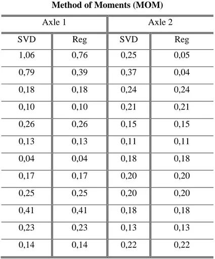
Table III.1. Comparison of EP of Two Axle Constant Loads Under 5% Noise
Using the Regularization and the SVD Solutions for Different Sensor Locations...55
Table III.2. Bridge Model Characteristics...57
Table III.3. Max and Min Displacement Values with the Corresponding Modes…...60
Table III.4. Bridge Model Description………...65
Table III.5. Modal Properties of Output Model Results………....66
Table IV.6 Max and Min Displacements of Mid-Span………...84
Table V.7 Physical and Mechanical Characteristics of Isolation Bearing………100
xiv
List of Symbols
a: Amplitude α: Coefficient vector An C: Damping (t): Function of timeE(x): Variance function EI: Bending Stiffness
f(t): Evolutionary random excitation g(t): Slowly varying modulation function Hy
ϒ
(ɷ): Frequency response function j
K: Stifness
: Mode participation factor
M: Mass Ne n : Shape function k ф : Wave number j Ф
: Mass normalized mode
n Ф
(x): Mode shapes x
ω: Frequency
(ɷ,T): Energy density spectrum
Ωn Ω
: The generalized flexible dynamic frequency
p
P(X,t): Probability density function
: The disturbance frequency of the harmonic load
ψj ψ
: Eigenpairs
k
Q: Maximum frictional force
: Basis function
r: Rank of Sxx
R: Radius of curvature
(ɷ)
xv
Rx(τ): Cross-correlation function Sx(ω): Power Spectral Density Function t: Time
T: Period Tc
θ
: The required time of the harmonic force k
V: Base shear
:Random phase angle
W: Weight
X: Random variable
x(t): Time variable function XT
x͂, ỹ,z͂: Response vectors
(ω): Fourier transform function ẍg
ẍ ͂
(t): Ground acceleration g
y: displacement vector
(t): Pseudo ground acceleration
xvi
List of Abbreviations
2D: Two Dimensions 3D: Three Dimensions
AASHTO: American Association of State of Highway Transportation Officials ASD: Acceleration Spectral Density
CA: Cellular Automaton
CIP/PS: Cast-In-Place/Prestressed
CQCA: Conventional Complete Quadratic Combination Algorithm DOF: Degree of Freedom
EP: Error Percentage
FEM: Finite Element Method FEMs: Finite Element Models FPS: Friction Pendulum System FT: Fourier Transform
ISO: International Organization for Standardization LRB: Lead Rubber Bearing
MOM: Method of Moments
PDF: Probability Density Function PEM: Pseudo Excitation Method PSD: Power Spectral Density
PSDF: Power Spectral Density Function NDT: Non Destructive Testing
RQPE: Real Quantity of Percentage Error SCMs: Structural Component Models SVD: Singular Value Decomposition ULS: Ultimate Limit State
VB: Vehicle Bridge system
Chapter I
Chapter I : Research Background
2015-2016
Dynamic Analysis of Highway Bridges Under
Multiple Random Excitations 6
Introduction
The interaction between bridges, vehicles, winds and earthquakes presents a complicated dynamic problem; a large number of variables controls the dynamic interaction of the system. An insight into the mechanics of this problem is essential to develop an efficient numerical method for its analysis. In this way, a large number of analytical and experimental investigations have been carried out in the past to study the dynamic behaviour of bridge decks that are subjected to time varying loads.
There is growing interest nowadays in the process of designing bridge engineering structures to withstand dynamic loads. Essentially, dynamic analyses focus on evaluation of time dependent displacements, from which the stress state of the structure in question can be computed. The most basic pieces of information needed for this are the natural period which is a function of the structure’s mass and stiffness, and the amount of available damping (or, equivalently, the amount of energy that can be absorbed by the structure). This section gives an overview on the bridges failure under dynamic loads over the world in the last four decades in addition to the progress of scientific research in bridge design and health monitoring using analytical, numerical and experimental methods.
I.1. Bridges Dynamic Loads and Failure
Bridges are an important part of the surface transportation system. Failure in a bridge operation can cause severe economic, environmental and/or social consequence. A considerable number of bridge failures, caused by natural or human-made forces, can be prevented by theoretical studies, updating design criteria, re-evaluating safety and structural maintenance.
Today, about one half of the bridges in the world have aged more than 40 years. On average, about 12% of existing bridges are already structurally deficient and need repairs, strengthening, maintenance and perhaps closure (Kappos,
Chapter I : Research Background
2015-2016
Dynamic Analysis of Highway Bridges Under
Multiple Random Excitations 7
A.J.2002). The critical situation can be where two or more failure causes happen at the same time. For example, a structurally deficient bridge under overloading conditions can be significantly in danger of collapse. Moreover many highway bridges have been built throughout the world in the past few decades to meet the economic, social and recreational needs of communities. Some of these bridges have main span lengths of more than 1000m, such as the Akashi Kaikyo Bridge (1991m, Japan, 1998), the Xihoumen Bridge (1650m, China, 2009), the Great Belt Bridge (1624 m, Denmark, 1998), and the Run Yang Bridge (1490 m, China, 2005). Some of them carry both road and rail traffic, such as the Tsing Ma Bridge (1377m, Hong Kong, 1997), the Minami Bisan-Seto Bridge (1100m, Japan, 1989), and the 25 de Abril Bridge (1013m, Japan, 1966). Most of these bridges are located in wind-prone regions, and long-span length makes them susceptible to strong crosswinds (Chen, Z.W.2010).
Further, the increases in traffic volume and gross vehicle weight that accompany economic development significantly affect the local dynamic behaviour of such bridges. Most of highway bridges are multi loaded since they are simultaneously suffering from a combination of effects of dynamic loading, such as railway, highway, wind and seismic loading. Multi-load bridges play significant roles in the entire transportation system, and thus it is critically important to protect such immense capital investments and ensure user comfort and bridge safety.
I.1.1. Bridges Failure Meaning
In the broadest sense, failure of a bridge occurs whenever it is unable properly to fulfil its function. It may be found that a bridge is unable to carry its full design loads and, for this reason, a load restriction is placed on the bridge. This is, in a sense, a failure. A gain, the form of the bridge may be such that, in periods of high wind, traffic is unable to cross.
Chapter I : Research Background
2015-2016
Dynamic Analysis of Highway Bridges Under
Multiple Random Excitations 8
Bridge failures may happen at any stage of the bridge life time. Collapse can be present in older bridges, newly designed bridges, and even those which are under construction. Deterioration of the bridge elements and inadequate design criteria in older codes can be two main reasons for collapse of old bridge structures.
I.1.2. Failure Causes
Beside deterioration and lack of regular inspection and maintenance, design errors and unpredicted loads can also cause collapse of bridges including new and/or old bridge structures. Hydraulic loads, collision, overloading, deterioration, earthquake and construction have been measured as the most destructive causes of bridge failures. For example, deteriorated elements subjected to overloads or earthquake excitations might be a source of damage and possible structural collapse.
In practice, failures occur in different forms in a material and are likely to be different for steel, concrete, and timber bridges. Common types of failure that occur in steel bridges are yielding (crushing, tearing or formation of ductile or brittle plastic hinges), buckling, fracture and fatigue (reduced material resistance, reversal of stress in welds and connections, vibrations), shearing and corrosion. Large deformations due to impact, sway, violent shaking during seismic events, erosion of soil in floods or settlement due to expansive soils may induce failure in both steel and concrete bridges.
The most common causes of bridge failure include: overstress of structural elements due to section loss, design defects and deficiencies, long- term fatigue and fracture, failures during construction, accidental impacts from ships, trains and aberrant vehicles, fire damage, earthquakes, lack of inspection and unforeseen events. The data base of bridges inspection all over the world shows that the most touched types of bridges between the periods 1989 to 2001 are the steel construction and beam/girder bridges due to corrosion and traffic loading (Wesley,C. 2014) however, this estimation can’t be generalized for all kinds of
Chapter I : Research Background
2015-2016
Dynamic Analysis of Highway Bridges Under
Multiple Random Excitations 9
bridges that depends on the country number of bridges for each type, the general climate conditions and population.
I.1.3. Failure Mechanism
Bridges have historically presented significant vulnerabilities during major seismic, wind and over loading traffic events, they present fundamental infrastructure to evacuate the affected people and to transport the emergency equipment and materials when a natural or human events occurs. For this raison, their loss of function or failure will result the loss of lives and several economical consequences. The following summarizes the failure mechanisms of highway bridges, including the observation of span collapse, structure component damages, and other structural component damages.
I.1.3.1. Unseating
During earthquakes, structure displacement is a major cause of highway bridge span damage and failure. Excessive displacements in the longitudinal direction can fail the bridge via unseating of the superstructure as shown in Fig.I.1.
Fig. I.1 Example of Unseating Failure in the 1999 Chi-Chi Earthquake in Taiwan (Viewed on https://mceer.buffalo.edu)
Chapter I : Research Background
2015-2016
Dynamic Analysis of Highway Bridges Under
Multiple Random Excitations 10
Moreover, deck pounding or unseating failure can occur during hurricane due to serge and wave loads because of the lack connection between the bridge components. That is particularly possible for simply supported highway bridges if seats or corbels located at the abutments or piers don’t possess sufficient length. The entire superstructure span can become unseated, resulting in sudden bridge collapse (Ataei ,N . et al. 2012).
Moreover, the low stiffness, light weight and long spans of bridges make the lateral and torsional stiffness of these bridges low in comparison with regular non-cable bridges. Bridges built in vast areas such as rivers, coasts, and valleys are exposed to wind loads. The speed of the wind through a bridge varies frequently; in some moments it decreases and in some moments it increases.
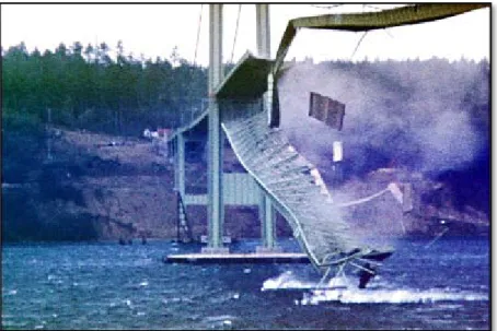
Due to the above mentioned conditions, a lot of collapses and performance failures have happened since the bridge invention. Tacoma Narrows Bridge (Wiki Failures) and Silver Bridge over Ohio River are two examples of cable bridge failures which led to complete collapse of structures. In Fig.I.2 the Tacoma Narrows Bridge is shown at the moment of collapse, it can be observed the total failure of the super structure despite the columns and substructure strength.
Fig. I.2: Tacoma Narrows Bridge after Collapse Due to Wind Fluttering (Viewed on https://en.wikipedia.org)
Chapter I : Research Background
2015-2016
Dynamic Analysis of Highway Bridges Under
Multiple Random Excitations 11
I.1.3.2. Column Flexural Failure
The two main reasons for column failure are the insufficient deformation capacity which results in flexure-shear and flexure failure and the lack of shear resistance which results in shear failure, Fig.I.3 is an example of column flexural failure which comes from the deficient reinforcement design for the unexpected seismic shaking, characterized by inadequate strength or inadequate ductility.
Flexural failure usually occurs when the longitudinal confinement is not sufficient, which leads to concrete crush as strains exceed the capacity and the column is not tough to sustain the imposed flexural deformations without failure.
Fig. I.3 Column Flexural Failure Due to Insufficient Ductility in the 1995 Kobe Earthquake
(Viewed on http://www.eng.buffalo.edu)
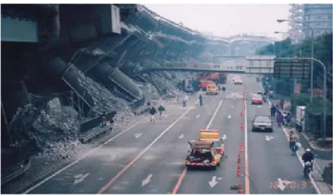
I.1.3.3. Column Shear Failure
The column shear failure is characterized by the failure of the transverse shear reinforcement. Shear failure resulting from seismic shaking is more prominent in old highway bridges due to insufficient shear reinforcement resulting in brittle and sudden failure. Such failures can occur at relatively low structural displacements,
Chapter I : Research Background
2015-2016
Dynamic Analysis of Highway Bridges Under
Multiple Random Excitations 12
at which stage the longitudinal reinforcement may have not yet yielded. Examples of shear failure can be found in several of the historical earthquakes as illustrated in Fig.I.4. Failure of a column can result in loss of vertical load carrying capacity which is often the primary cause of bridge collapse.
Fig. I.4 Shear Failure of Columns in Hanshin Expressway (Viewed on http://www.fhwa.dot.gov)
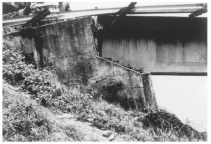
I.1.3.4. Joint Failure
Joint failure can occur for various reasons, but experience shows that failures falls into several distinct categories. This list includes, but is not limited to: shipping and handling damage, improper installation/insufficient protection, during/after installation, improper anchoring, guiding, and supporting of the system, anchor failure in service, corrosion, system over-pressure, excessive bellows deflection, torsion, bellows erosion, and particulate matter in bellows convolutions restricting proper movement.
Joints may be exposed to critically damaging actions when the joints lie outside of the superstructure as shown in Fig.I.5. Although joint failures occurred in previous earthquakes, significant attention was not paid to joints until several spectacular failures were observed following the 1989 Loma Prieta earthquake.
Chapter I : Research Background
2015-2016
Dynamic Analysis of Highway Bridges Under
Multiple Random Excitations 13
Fig. I.5 Joint Damage to the Embarcadero Viaduct in San Francisco (Viewed on http://www.fhwa.dot.gov)
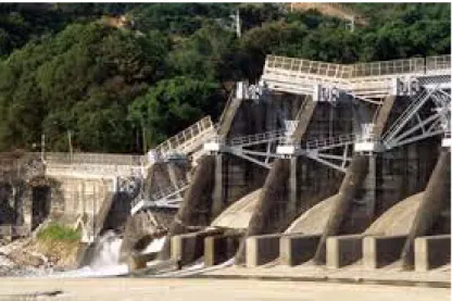
1.1.3.5. Damages in Foundation
Reports of foundation failures during hard phenomena like wind and earthquakes are relatively rare, with the notable exception of situations in which liquefaction occurred. It is not clear whether failures are indeed that rare or whether many foundation failures are undetected because they remain underground. There are many reasons why older foundations might be vulnerable. Piles might have little confinement reinforcement, yet be subjected to large deformation demands. Older spread and pile-supported footings rarely have top flexural reinforcement or any shear reinforcement.
When considering the bridge structure alone, the actual behaviour of the bridge under dynamic loads may significantly differ from that from the analysis since the response of a bridge depends not only on the bridge itself, but also on the characteristics of the dynamic loads to which it is subjected.
The assumption of fixed support for a bridge upheld on soft soil ignores the interaction effects that result from the scattering of waves when reaching the foundation surface (kinematic interaction) and the flexibility and energy
Chapter I : Research Background
2015-2016
Dynamic Analysis of Highway Bridges Under
Multiple Random Excitations 14
dissipation of foundation-soil system (inertial interaction). These interaction effects lead to dynamic responses that may differ considerably in amplitude and frequency from what is obtained when a fixed support is assumed.
Foundation damage associated with liquefaction-induced lateral spreading has probably been the single greatest cause of extreme distress and collapse of bridges. The problem is especially critical for bridges with simple spans. The 1991 Costa Rica earthquake provides many examples of foundation damage. Fig.I.6 shows an abutment that rotated due to liquefaction and lateral spreading.
Fig. I.6 Abutment Failure during the 1991 Costa Rica Earthquake (Viewed on http://www.u-cursos.cl)
The failure mechanism of pile is related to the force conditions of pile under dynamic loading, so the failure mechanism can be subcategorized to three types (Datta, T.K. 2010):
(1) The failure caused by additional dynamic stress that is induced by vibration. Such failure mode generally occurs when the ground motion level is high, the quality of pile is poor, and the soil layer is weak. Under such conditions, the reaction forces to piles from surrounding soil are relatively small, the deformation of piles are relatively large, and relatively big additional dynamic stresses are generated in pile shaft.
Chapter I : Research Background
2015-2016
Dynamic Analysis of Highway Bridges Under
Multiple Random Excitations 15
(2) The failure caused by additional static stress that is induced by soil lateral movement. Such failure mode usually occurs at bank-side site.
(3) The length of pile penetrating into steady soil layer is not enough or pile tip don’t arrive at steady soil layer, so pile foundation is easy to lose bearing capacity due to liquefaction of sandy soil under dynamic loading.
I.2. Literature Review on Bridges Dynamics Analysis
Bridge vibration has been a concern to bridge designers and users for years. Much of the earlier studies of bridge vibration were begun after bridge failures due to vibration. Perhaps the most well known was Tacoma Narrows Bridge failure due to lateral vibrations from wind. Many of the problems however have only recently been addressed, through analytical and field studies.
Currently, bridge vibration studies include: suspension bridges, cable-stayed bridges, curved bridges, prestressed concrete bridges, and high speed transit structure bridges. Analytical studies and computer models are being used to handle such items as acceleration and deceleration of vehicles,surface roughness of the bridge deck, and multi-vehicle loading.
I.2.1. Field Tests
Much of the initial work in bridge vibration began with actual bridge testing. This enabled the researchers to identify the factors that most affected bridge vibrations. The initial tests involved simple span bridges only. This was followed by the study of multispan bridges and then by more complicated bridges, such as suspension bridges.
There were five simple span dynamic bridge field studies. (Kinnier, K.H. and Mckeel, W.T. 1965) looked at the influence of the bridge substructure on the dynamic behaviour. Their first study compared conventional and elastomeric influence bearings on a rolled-beam, composite bridge. In their second study, they
Chapter I : Research Background
2015-2016
Dynamic Analysis of Highway Bridges Under
Multiple Random Excitations 16
compared tall and short piers on a composite bridge by measuring strains and deflections caused by a 3-axle tractor-trailer. The earliest of the other three studies involved AASHO Road Tests. These involved 18 three beam bridges with 14 different vehicles. Both deflections and strains were measured.
The next study was by (Lashomb, S. M. et al.1985). They tested two steel stringer bridges and three plate-girder bridges with the load applied by a 2-axle, 10 ton dump truck. They measured deflections with a deflectometer and accelerometers. The remaining study was by (Biggs, J. M. 1964). He tested two single medium span stringer types through girder bridges, with the load applied by a 2-axle dump truck. The deflection was measured by deflectometers at mid-span, and strains and accelerations were measured on the axles of the truck.
Seven field studies were made involving both simple and continuous span bridges. (Billing, J.R. and Green,R. 1984) reviewed three series of dynamic tests done in Ontario, Canada in 1956 to 1957, 1969 to 1971, and 1980. In the first two series, deflection was measured, while in the last series, acceleration was measured. In the last two series, test vehicles were used. (Funkhouser, D. W. and Heins) tested 40 bridges with five different types of vehicles obtaining stress versus time records at several locations along the bridge.
(Green, R. 1997) summarized 52 bridge tests involving with both a test vehicle and normal traffic loading. He measured the deflections with a deflectograph. (Eyre, R. and Tilly, G. P. 1977) tested 23 bridges for damping characteristics by exciting 22 of them with reciprocating weights and one by dropped weights. (Schilling, C.G., Klippstein, K.H., Barsom, J.M. and Blake, G.T. 1978) studied fatigue in bridges by summarizing 15 field bridge tests subject to traffic loading.
Perhaps the most complete study was that by (Gaunt, J. T. and Sutton C. D. 1981). They tested 62 bridges under normal traffic and a test vehicle. Both accelerations and deflections were measured. Ten field studies were made specifically on continuous span bridges. (Green, R.1977) studied two 3-span plate girder bridges with a tractor trailer combination. They measured strains for a
Chapter I : Research Background
2015-2016
Dynamic Analysis of Highway Bridges Under
Multiple Random Excitations 17
variety of loading cases. At about the same time as Edgerton and Beecroft‘s study, (Hayes, J. M. and Sbarounis, J. A. 1997) tested a 3-span, continuous, I-beam bridge by measuring strains due to vibrations caused by a test truck.
Another study in the same field was a test on an 8-span plate girder bridge and a 6-span rolled beam-bridge with 2-axle and 3-axle trucks and normal traffic where deflections were measured with a deflectometer. The next study was by (Gillespie, T. D. 1992) who tested four continuous span bridges. The loading was a van truck and a tractor trailer combination, and response was measured by strain gages.
In the last years dynamic testing and dynamic analyses has become a very useful tool on the health monitoring of the bridges all over the world. The strength and integrity of bridges will decrease during the serviceability stage due to the degradation mechanisms induced by traffic, wind, temperature, corrosion and environmental deterioration.
In order to detect the abnormal changes through non-destructive testing (NDT) technology or periodical evaluation (Montgomery, D. C. 2008), a fundamental but critical step is to obtain dynamic responses at some critical bridge locations. The mostly concerned dynamic responses of a multi-load bridge may include global response (displacement, velocity, and acceleration) and local response (acceleration and stress), which are mainly induced by traditional live load (such as highway, railway and wind loading) or accidental live load (such as ship impact and earthquake). Structural intrinsic characteristics could be extracted from these dynamic responses (or vibration signals) to develop all sorts of vibration-based damage detection techniques.
A well-known family of them is based on structural dynamic characteristics (such as frequencies, mode shapes, damping ratios, and strain mode shapes) and their derivatives. Some damage identification approaches were proposed based on the dynamic responses of bridge structures under moving vehicle loads. The dynamic responses of highway bridges also could be used for structural
Chapter I : Research Background
2015-2016
Dynamic Analysis of Highway Bridges Under
Multiple Random Excitations 18
assessment, for example, fatigue assessment at the critical locations over the service history of the bridge and assessment of extreme events such as complex traffic congestion coupled with moderate or even strong wind.
I.2.2. Bridge Structural Modelling and Analysis
Design of reinforced concrete bridges is normally done on the basis of a structural analysis. The purpose of the analysis is to find a distribution of sectional forces which fulfils equilibrium and is suitable for design. In the past structural analyses were often done with simplified models, for example two-dimensional (2D) equivalent beam or frame models. Such models are not able to describe the distribution of forces in transversal directions. Therefore a design according to a 2D equivalent model will not be according to the true linear elastic distribution, even though the design might fulfill requirements in ultimate limit state (ULS) after sufficient plastic redistribution (Mattias, Grahn. 2012).
With the recent introduction of (EUROCODE 2, 2005), (ASHTO, 2003) and the SWEDISH Transport Administrations the demands on structural analysis has been updated. A model for structural analysis has to be able to describe the response of the structure in its entirety. In practice this implies that 2D equivalent models are not sufficient and a 3D analysis describing the forces in multiple directions is needed.
I.2.2.1 Structural Modelling
Structural modelling is a tool to establish three mathematical models, including a structural model consisting of three basic components: structural members, joints (nodes, connecting edges or surfaces), and boundary conditions (supports and foundations); a material model and a load model. For designing a new structure, connection details and support conditions shall be made as close to the computational models as possible. For an existing structure evaluation, structures shall be modelled as close to the actual as-built structural conditions as possible.
Chapter I : Research Background
2015-2016
Dynamic Analysis of Highway Bridges Under
Multiple Random Excitations 19
The correct choice of modelling and analysis methods depends on the importance of the structure, the purpose of structural analysis and the required level of response accuracy.
Different types of elements may be used in bridge models to obtain characteristic responses of a structure system. Elements can be categorized based on their principal structural actions including: truss element, beam element, frame element, plate element, shell, plane element, solid and the NlLink element. Selecting the proper boundary condition has an important role in structural analysis. Effective modelling of support conditions at bearings and expansion joints requires a careful consideration of continuity of each translational and rotational component of displacement. For a static analysis, it is common to use a simpler assumption of supports (i.e. fixed, pinned, roller) without considering the soil/foundation system stiffness. However for dynamic analysis, representing the soil/foundation stiffness is essential. In most cases choosing a [6×6] stiffness matrix is adequate. There are two types of loads in a bridge design:
- Permanent Loads: Loads and forces that are assumed to be either constant
upon completion of construction or varying only over a long time interval (AASHTO 3.2). Such loads include the self weight of structure elements, wearing surface, curbs, parapets and railings, utilities, locked-in force, secondary forces from post-tensioning, force effect due to shrinkage and due to creep, and pressure from earth retainments (CA 3.3.2).
- Transient Loads: Loads and forces that can vary over a short time interval
relative to the lifetime of the structure (AASHTO 3.2). Such loads include gravity loads due to vehicular, railway and pedestrian traffic, lateral loads due to wind and water, ice flows, force effect due to temperature gradient and uniform temperature, and force effect due to settlement and earthquakes (CA 3.3.2).
The formulation of a mathematical model using discrete mathematical elements and their connections and interactions to capture the prototype behaviour is called Discretization (Barker, R. M. and Puckett, J. A. 2013). For this purpose:
Chapter I : Research Background
2015-2016
Dynamic Analysis of Highway Bridges Under
Multiple Random Excitations 20
Joints/Nodes are used to discretize elements and primary locations in structure at which displacements are of interest, elements are connected to each other at joints, masses, inertia, and loads are applied to elements and then transferred to joints, a typical model discretization for a bridge bent is shown on fig.I.7.
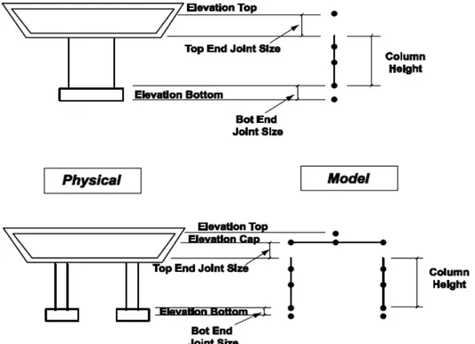
Fig. I.7 Model Discretization for Monolithic Connection (Structural Modelling and Analysis 2015)
Based on the Structural Modelling Guidelines, the bridge construction can be modelled by the following three steps:
- Lumped-Parameter Models (LPMs): The bridge mass, stiffness, and
damping components are usually combined and lumped at discrete locations. It requires significant experience to formulate equivalent force-deformation with only a few elements to represent structure response. For a cast-in-place prestressed (CIP/PS) concrete box girder superstructure, a beam element located at the centre of gravity of the box girder can be used. For non-box girder structures, a detailed model will be needed to evaluate the responses of each separate girder.
Chapter I : Research Background
2015-2016
Dynamic Analysis of Highway Bridges Under
Multiple Random Excitations 21
- Structural Component Models (SCMs): Based on idealized structural
subsystems/elements to resemble geometry of the structure, structure response is given as an element force-deformations relationship. Gross moment of inertia is typically used for non-seismic analysis of concrete column modelling. Effective moment of inertia can be used when analyzing large deformation under loads, such as prestressing and thermal effects. Effective moment of inertia is the range between gross and cracked moment of inertia.
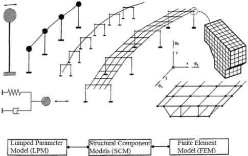
- Finite Element Models (FEMs): A bridge structure is discretized with
finite-size elements. Element characteristics are derived from the constituent structural materials (AASHTO 4.2). Fig. I.8 shows the levels of modelling for seismic analysis of bridge structures.
Fig. I.8 Levels of Modelling for Seismic Analysis of Bridge (Priestley, et al 1996)
I.2.2.2 Structural Analysis and Analytical Solutions
Structural analysis is a process to analyze a structural system to predict its responses and behaviours by using physical laws and mathematical equations. The main objective of structural analysis is to determine internal forces, stresses and deformations of structures under various load effects.
Chapter I : Research Background
2015-2016
Dynamic Analysis of Highway Bridges Under
Multiple Random Excitations 22
Analytical equations to describe bridge vibration behaviour were initially developed by (Inglis,C.E.1913) for railroad bridges and (Timoshenko, S. and Young, D.H. 1940) for suspension bridges in the early 1900‘s. In the 1950‘s and early 1960‘s actual bridge tests, particularly of simple single span bridges, were undertaken to study bridge vibrations and to understand the parameters involved. Also during this time, model testing in the laboratory and simplified beam and moving force analytical models were used to study bridge vibrations.
As computers became more available in the 1960‘s and 1970‘s, much of the analytical work was done in developing computer models to describe both bridge vibrations and vehicles with sprung and unsprung mass models. During the same period, actual field tests of bridges began on more complicated bridges such as continuous bridges.
Typically, during the analytical phase of any bridge design, finite-element-based structural analysis programs are used to evaluate the structural integrity of the bridge system. Most structural analysis programs employ sound, well-established finite-element methodologies and algorithms to solve the analytical problem. Others employ such methods as moment distribution, column analogy, virtual work, finite difference, and finite strip, to name a few. It is of utmost importance for the users of these programs to understand the theories, assumptions, and limitations of numerical modelling using the finite-element method, as well as the limitations on the accuracy of the computer systems used to execute these programs. Many textbooks are available to study the theories and application of finite-element methodologies to practical engineering problems. It is strongly recommended that examination of these textbooks be made prior to using finite-element-based computer programs for any project work. For instance, when choosing the types of elements to use from the finite-element library, the user must consider some important factors such as the basic set of assumptions used in the element formulation, the types of behaviour that each element type captures, and the limitations on the physical behaviour of the system. Other important issues to consider include numerical solution techniques used in matrix
Chapter I : Research Background
2015-2016
Dynamic Analysis of Highway Bridges Under
Multiple Random Excitations 23
operations, computer numerical precision limitations, and solution methods used in a given analysis.
There are many solution algorithms that employ direct or iterative methods, and sparse solver technology for solving the same basic problems; however, selecting these solution methods efficiently requires the user to understand the best conditions in which to apply each method and the basis or assumptions involved with each method. Understanding the solution parameters such as tolerances for iterative methods and how they can affect the accuracy of a solution are also important, especially during the nonlinear analysis process.
Dynamic analysis is increasingly being required by many design codes today, especially in regions of high seismicity. Response spectrum analysis is frequently used and easily performed with today’s analysis tools; however, a basic understanding of structural dynamics is crucial for obtaining the proper results efficiently and interpreting analysis responses. Basic linear structural dynamics theory can be found in many textbooks. While many analysis tools on the market today can perform very sophisticated analyses in a timely manner, the user too must be more savvy and knowledgeable to control the overall analysis effort and optimize the performance of such tools.
Conclusion
In general it could be said that verification and interpretation of 3D bridge structure behavior can be difficult under multiple presence of dynamic loads. The combination of dead and live loads with the bridge model presents a very complex problem to solve; a big number of parameters have to be considered.
Studies shown above were based mainly on either static amplificated equivalence, field test with strict parameters and an existing bridge construction or numerical analyses applied on a simplified bridge structure and one type of dynamic loading.
Chapter I : Research Background
2015-2016
Dynamic Analysis of Highway Bridges Under
Multiple Random Excitations 24
Since every bridge structure presents a dynamic model because of its own properties (length, type, elevation, climatic conditions, service type) it is not advised to consider a model and apply its results on the others, moreover an existing construction and in construction one don’t behave in the same way.
In short, since modelling in 3D is in principle requirement for structural analysis today, it is beneficent to analyze the dynamic behaviour of a bridge under dynamic loads with a multiple presence and apply a model for each geometric kind of bridge construction.
Chapter II
Chapter II : Random Vibrations
2015-2016
Dynamic Analysis of Highway Bridges Under
Multiple Random Excitations 25
Introduction
Every structure in civil engineering constitutes a continuous system when subjected to a time varying load, this system undergoes a vibratory behaviour. Vibrations are an engineering concern in this area because they may cause a catastrophic failure (complete collapse) of the structure because of excessive stresses and amplitudes (resulting mainly from resonance) or because of material fatigue over a period of time.
Vibrations of continuous systems is a particularly interesting subject where it is important to realize theoretically how do strings, rods, beams, plates, shells and other continuous bodies vibrate, with which shapes and at what frequencies, how they respond when subjected to dynamic exciting forces and pressures , all these information must be well studied to achieve the structure security.
Vehicle loads, earthquakes and wind are highly unpredictable events and time varying forces; their time of occurrence, frequency value, magnitude and duration are all variables which can’t be known in advance that’s why they are considered as source of random vibration and the best way of their characterization is the probability methods.
Random vibrations, which in recent years has found extensive applications in structural dynamics, machine vibrations, earthquake engineering, as well as in non-destructive testing and identification. We note that the concepts of random variables and random (or stochastic) processes, the latter being functions of both space and time in their most general form.
For instance, wind, water wave and earthquake-induced ground motions are loadings of random nature. Specifically, the former two types of loads can be viewed as comprising a rapidly fluctuating part superimposed on a slowly varying mean value. They can be classified as stationary random loads in the sense that there is a certain periodicity (and hence some predictability) in the fluctuating part. Earthquake loads are fully random and classified as non-stationary, a term that will be explained later on. Finally, there is some mild
Chapter II : Random Vibrations
2015-2016
Dynamic Analysis of Highway Bridges Under
Multiple Random Excitations 26
stochasticity inherent in traffic induced loads, simply because the movement of vehicles cannot be fully controlled.
This section is a theoretical research background on vibrations but puts most emphasis on bridges vibration sources and mathematical structure analyses, where the dynamic loads applied on bridges were considered as random excitation.
II.1. Basic Terminology of Structural Vibration
The term vibration describes repetitive motion that can be measured and observed in a structure. Unwanted vibration can cause fatigue or degrade the performance of the structure. Therefore it is desirable to eliminate or reduce the effects of vibration.
In other cases, vibration is unavoidable or even desirable. In this case, the goal may be to understand the effect on the structure, or to control or modify the vibration, or to isolate it from the structure and minimize structural response.
Vibration analysis is divided into sub-categories such as free vs. forced vibration, sinusoidal vs. random vibration (Ryan, T. P. 2000), and linear vs. rotation-induced vibration.
Free vibration: Is the natural response of a structure to some impact or
displacement. The response is completely determined by the properties of the structure, and its vibration can be understood by examining the structure's mechanical properties. For example, when you pluck a string of a guitar, it vibrates at the tuned frequency and generates the desired sound. The frequency of the tone is a function of the tension in the string and is not related to the plucking technique.
Forced vibration: Is the response of a structure to a repetitive forcing function
that causes the structure to vibrate at the frequency of the excitation. For example, the rear view mirror on a car will always vibrate at the frequency associated with
Chapter II : Random Vibrations
2015-2016
Dynamic Analysis of Highway Bridges Under
Multiple Random Excitations 27
the engine's RPMs. In forced vibration, there is a relationship between the amplitude of the forcing function and the corresponding vibration level. The relationship is dictated by the properties of the structure.
Sinusoidal vibration: Is a special class of vibration, the structure is excited by
a forcing function that is a pure tone with a single frequency. Sinusoidal vibration is not very common in nature, but it provides an excellent engineering tool that enables us to understand complex vibrations by breaking them down into simple, one-tone vibrations. The motion of any point on the structure can be described as a sinusoidal function of time.
Random vibration: Is very common in nature, the vibration you feel when
driving a car result from a complex combination of the rough road surface, engine vibration, wind buffeting the car's exterior, etc. Instead of trying to quantify each of these effects, they are commonly described by using statistical parameters. Random vibration quantifies the average vibration level over time across a frequency spectrum (Wirsching, P. H., Paez, T. L. and Ortiz, K. 2006).
II.2. Random Processes II.2.1. Theory and Definition
Random vibration is somewhat of a misnomer. If the generally accepted meaning of the term "random" were applicable, it would not be possible to analyze a system subjected to "random" vibration. Furthermore, if this term were considered in the context of having no specific pattern (i.e., haphazard), it would not be possible to define a vibration environment, for the environment would vary in a totally unpredictable manner (Newland, D.1993).
Fortunately, this is not the case. The majority of random processes fall in a special category termed stationary. This means that the parameters by which random vibration is characterized do not change significantly when analyzed statistically over a given period of time - the RMS amplitude is constant with
Chapter II : Random Vibrations
2015-2016
Dynamic Analysis of Highway Bridges Under
Multiple Random Excitations 28
time. For instance, the vibration generated by a particular event, say, a missile launch, will be statistically similar whether the event is measured today or six months from today (Robson, J. D.1964), By implication, this also means that the vibration would be statistically similar for all missiles of the same design. It is possible to subdivide a process into a number of sub-processes, each of which could be considered to be stationary. For example, a missile environment could consist of several stationary processes, such as: captive carry, buffet, launch and free flight. Each of these sub-processes has unique amplitude, frequency and time characteristics, requiring separate analyses and considerations.
The assumption of a stationary process is essential in both a technical and legal sense. As previously stated, it would not be possible for a designer to analyze a system, nor for a user to test a system prior to installation in the field, if the vibration excitation were not stationary. Consequently, it would not be possible to develop a legally binding specification. In subsequent conversations, it is assumed that the random excitation is a stationary process.
Any vibration is described by the time history of motion, where the amplitude of the motion is expressed in terms of displacement, velocity or acceleration.
Fig.II.1 Amplitude-Time History of Sinusoidal Vibration
Chapter II : Random Vibrations
2015-2016
Dynamic Analysis of Highway Bridges Under
Multiple Random Excitations 29
Sinusoidal vibration is the simplest motion, and can be fully described by straightforward mathematical equations. The Fig.II.1 shows the amplitude time plot of a sinusoidal vibration and indicates that sinusoidal vibration is cyclic and repetitive. In other words, if frequency and amplitude (or time and amplitude) are defined the motion can be predicted at any point in time.
A random vibration is one whose absolute value is not predictable at any point in time. As opposed to sinusoidal vibration, there is no well defined periodicity, the amplitude at any point in time is not related to that at any other point in time, Fig.II.2 shows the amplitude time history of a random vibration where the lack of periodicity is apparent.
A major difference between sinusoidal vibration and random vibration lies in the fact that for the latter, numerous frequencies may be excited at the same time (Hasselman, T. K. and Hart, G. C., 1972). Thus structural resonances of different components can be excited simultaneously, the interaction of which could be vastly different from sinusoidal vibration, wherein each resonance would be excited separately.
Fig.II.2 Amplitude-Time History of Random Vibration (Viewed on http://www.intechopen.com)
Chapter II : Random Vibrations
2015-2016
Dynamic Analysis of Highway Bridges Under
Multiple Random Excitations 30
The most obvious characteristic of random vibration is that it is non-periodic. The knowledge of the past history of random motion is adequate to predict the probability of occurrence of various acceleration and displacement magnitudes, but it is not sufficient to predict the precise magnitude at a specific instant (Dave Steinberg, D. 1988).
Although the instantaneous amplitude of a random vibration cannot be expressed mathematically as an exact function of time, it is possible to determine the probability of occurrence of particular amplitude on a statistical basis.
To characterize a stationary process, an ensemble of possible time histories must be obtained, wherein the amplitude is measured over the frequency range of excitation. Thus, the three parameters of interest are: frequency, time and amplitude. This information would provide the ability to analyze a random process in a statistical sense.
The characterization of random vibration typically results in a frequency spectrum of Power Spectral Density (PSD) or Acceleration Spectral Density (ASD), which designates the mean square value of some magnitude passed by a filter, divided by the bandwidth of the filter. Thus, Power Spectral Density defines the distribution of power over the frequency range of excitation.
If the outcome of a (conceptual) experiment is to assign a real value to variable
x, then x is known as a random variable. Furthermore, if x assumes only a finite
number of values, it is called a discrete random variable. Finally, if x assumes a continuous range of values, it is called a continuous random variable.
II.2.2. Random Forcing Function and Response
Consider a turbulent airflow passing over an aircraft wing. The turbulent airflow is a forcing function. Furthermore, the turbulent pressure at a particular location on the wing varies in a random manner with time (Nigam, N.1983).