HAL Id: cea-01559397
https://hal-cea.archives-ouvertes.fr/cea-01559397
Submitted on 10 Jul 2017
HAL is a multi-disciplinary open access
archive for the deposit and dissemination of
sci-entific research documents, whether they are
pub-lished or not. The documents may come from
teaching and research institutions in France or
abroad, or from public or private research centers.
L’archive ouverte pluridisciplinaire HAL, est
destinée au dépôt et à la diffusion de documents
scientifiques de niveau recherche, publiés ou non,
émanant des établissements d’enseignement et de
recherche français ou étrangers, des laboratoires
publics ou privés.
Crowd-based personal radars for indoor mapping using
UWB measurements
Anna Guerra, Francesco Guidi, Lilia Ahtaryieva, Nicolo Decarli, Davide
Dardari
To cite this version:
Anna Guerra, Francesco Guidi, Lilia Ahtaryieva, Nicolo Decarli, Davide Dardari.
Crowd-based personal radars for indoor mapping using UWB measurements.
Ubiquitous Wireless
Broadband (ICUWB), 2016 IEEE International Conference on, Oct 2016, Nanjing, China.
�10.1109/ICUWB.2016.7790437�. �cea-01559397�
Crowd-Based Personal Radars for Indoor Mapping
using UWB Measurements
Anna Guerra
∗, Francesco Guidi
†‡, Lilia Ahtaryieva
∗, Nicol´o Decarli
∗, and Davide Dardari
∗ ∗DEI, University of Bologna, via Venezia 52, I-47521 Cesena (FC), Italy {anna.guerra3, nicolo.decarli, davide.dardari}@unibo.it
{lilia.ahtaryieva}@studio.unibo.it
†Univ. Grenoble-Alpes, 38000 Grenoble, France ‡CEA, LETI, MINATEC Campus, 38054 Grenoble, France
{francesco.guidi}@cea.fr
Abstract—The concept of personal radar has recently emerged as an interesting solution for future simultaneous localization and mapping (SLAM) applications. In this paper we evaluate the performance of an ultrawide-band (UWB) radar system for in-door environments mapping by exploiting a grid-based Bayesian approach able to combine all the measurements collected by radars adopting non-pencil beam antennas. In the proposed approach, the crowd will be involved by freely exploring the space, sending environmental partial views of it to cloud servers, where a complete map will be formed. Results show how the mapping accuracy can be improved thanks to the information collected from the crowd and considering different receivers schemes.
Index Terms—UWB, SLAM, indoor mapping, personal radar.
I. INTRODUCTION
Next Internet of Things (IoT) scenarios are expected to enable people and objects sharing their information in real time. Interconnected electronic devices acquire and exchange information on the surrounding world, thus creating a digital representation (mapping) of the real world into the so called smart space [1].
In this perspective, personal devices (e.g., smartphones, tablets and wearables) could represent a great sources of information allowing users to achieve an augmented ambient awareness thanks to the development of crowd-based appli-cations. These latter, based on the “power of crowd”, are expected to dramatically increase in their adoption thanks to the extreme connectivity and data sharing guaranteed by next 5th generation (5G) mobile devices [2]. The mobile crowd sensing paradigm has been intensely investigated [3], but, as the amount of data transferred can be huge, efficient compression schemes must be devised in view of what can be defined as an “acceptable information loss” in the mapping process. Moreover, tracking and localization in indoor scenar-ios still remains very challenging and a matter of research studies. SLAM-oriented solutions based on lidars or on vision technologies have been proposed in literature but, despite their capabilities of reconstructing environments, they need perfect visibility conditions to operate and require human active participation in the exploration process. To overcome these shortcomings, the concept of a smart personal radar
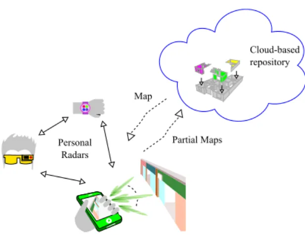
Personal Radars Cloud-based repository Partial Maps Map
Fig. 1. Crowd-based mapping using personal radars.
has been recently proposed in [4] as well as the adoption of dedicated high gain massive arrays for this kind of application [5]. In these works, the personal radar is based on a massive array operating at millimeter-wave (mmW) frequencies able to electronically scan the surrounding environment and to reconstruct a map of it. The choice of these technologies has been driven from one side to allowing the integration of massive arrays in small size, to the other by the necessity of achieving a high-definition distance estimate and very narrow steering beams which allow a high level of mapping reconstruction.
Contrarily, in this paper, the possibility of realizing a crowd-based personal radar working at ultrawide-band (UWB) frequencies for indoor environments mapping is investigated. If from one side, the possibility to adopt a near-pencil beam antenna could be lost, on the other side, the complexity reduces because a technological shift for the system realization is not yet necessary. The main novelty in the mapping approach is that the crowd will be involved in this process by freely moving within the space to be mapped, providing partial views of the users’ surroundings and sending them to cloud servers, where they will combined to form a more complete and less uncertain map. Such information will be then available to all users again for possible mapping refinements and for providing an infrastructure-less, low-cost, and highly accurate indoor localization system.
path A path B pA(1) pB(1) 0 0 0 0 0 0 1 1 1 1 1 1 1 1 1 1 2 2 2 2 2 2 4 4 4 4 6 6 6 6 8 8 8 8
Fig. 2. Map of the considered scenario consisting of two main paths where pA(1) is the starting position for users 1-2 and pB(1) for users 3-4.
The rest of the paper is organized as follows. Sec. II describes the measurement set-up and the considered UWB radar. Sec. III presents the mapping algorithm and finally, Sec. IV describes the case study and discuss the obtained measurement results. Sec. V concludes the work.
II. UWBINDOOR MEASUREMENTS
In order to validate the crowd-based personal radar concept, a measurement campaign has been conducted at the University of Bologna - Cesena Campus indoor premises. The considered scenario is shown in Fig. 2, and it consists of an area of 20 × 20 m2
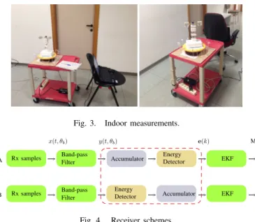
with two possible trajectories. Fig. 3 shows two photos taken during the measurement campaign. The measure-ment set-up consists of a Novelda!R NVA-R661 impulse radar1
connected to two UWB sinouos antennas with dielectric lenses and to a personal computer, placed on a mechanical positioner. The considered antennas, operating in the bandwidth6−8.5 GHz, present a gain of 6.7 dBi with an half power beam width (HPBW) of 40◦. The UWB antennas are placed in a
quasi-monostatic configuration and spaced apart of 0.14 m. Consequently, the effect of antenna coupling is significant and has to be suppressed through a time-gating operation.
The UWB NVA-R661 chip comprises the impulse generator, capable of transmitting short pulses over a large range of fre-quencies (6−10.2 GHz), a receiver to collect the backscattered environmental response and to provide the band-pass samples of the received waveform.
Measurements have been collected in different positions spaced of0.6 m in accordance with the two considered paths. At each measurement step, measurements have been collected from8 different angles (i.e., the set of observation angles have been set to O = {0◦, 45◦, 90◦, 135◦, 180◦, 225◦, 270◦, 315◦})
according to the sinuous antennas HPBW. To make the mea-surement set-up easily manageable, a rotating radar support position was placed on a trolley with wheels, as shown in Fig. 3.
1https://www.xethru.com/
Fig. 3. Indoor measurements.
A B Map x(t, θb) y(t, θb) Rx samples Rx samples Accumulator Accumulator Energy Energy Detector Detector Band-pass Band-pass Filter Filter EKF EKF e(k)
Fig. 4. Receiver schemes.
For each position and each steering direction, Np = 100
pulses have been transmitted with a central frequency of 6.8 GHz and a bandwidth W = 3 GHz. Starting from the collected received signals, two receiver schemes, whose block diagram is shown in Fig. 4, have been analysed. According to the receiver A (Fig. 4-top), first the received signals are accumulated to enhance the signal-to-noise ratio (SNR) and successively, the energy profile is computed; considering the receiver B (Fig. 4-bottom), energy profiles have been accu-mulated over the total number of emitted signals. The first approach could result in higher performance but at the expense of a higher receiver complexity while the second one is more appealing to be implemented in practical systems thanks to its simplicity, at the expense of a lower SNR. In both cases, before creating the energy profiles database, post-processing operations on the raw collected data have been performed to filter out the out-of-band interference and noise, and to suppress the coupling between the two UWB antennas.
In Figs. 5, an example of accumulated received signal according to the receiver A and an example of accumulated energy profile according to the receiver B are shown. In particular, they are collected in position pA(1), for a steering
direction equal to θb = 0◦. The energy profile has been
ob-tained by consideringNbintime bins of durationTED= 1/W .
III. MAPPING ALGORITHM
The described measurement campaign was conducted to enable the offline creation of the environment mapping by inferring the RCS of the surrounding objects. To this purpose, the extended Kalman filter (EKF) based probabilistic state-space approach described in [5] and reported in Algorithm 1 has been adopted. Differently from previous works, here, a crowd-based mapping approach is adopted in which the state estimation process could benefit from different users measure-ments. Specifically, referring to Fig. 2,2 users following path A are considered in the environment and other2 moving along path B with the same moving direction. At each time instant,
Algorithm 1: Mapping Algorithm
Data: Np,T set of positions in the considered trajectory, p(k) = p(1)
the initial radar position
Result: radar cross section (RCS) map of the environment
1 Initialization 2 while p(k) ∈ T do
3 Measurement step ◃ e(k) 4 Correction and update step;
5 Compute the innovation ◃ e(k) − ˆz(k|k − 1) 6 Compute the EKF update
7 Update the state ◃x(k|k)ˆ 8 Update the observation ◃ˆz(k|k)
9 Time Update (Prediction)
10 Predict the state ◃x(k + 1|k)ˆ
11 Predict the observation ◃z(k + 1|k)ˆ
12 Go to the next radar position. ◃ p(k) → p(k + 1)
0 5 10 15 20 25 30 35 -1.5 -1 -0.5 0 0.5 1 1.5 Delay [ns] r( t, θb =0 ◦) [m V ] 0 20 40 60 80 100 120 0 0.5 1 1.5 2 2.5 3x 10 -16 Bin index e ( θb =0 ◦) [J ]
Fig. 5. Accumulated received signal using the receiver A and energy profile using the receiver B over Np= 100 pulses.
the measurements of each users are exploited to estimate the updated version of the map by using the Algorithm 1.
To this end, the environment has been discretized inNL=
XgridYgridcells, and a RCS value, which has to be estimated at
the end of the mapping process, has been associated to each cell. According to the considered approach, the state vector of the system, that contains the parameters to be estimated in order to reconstruct the map, is given by
x(k) = m(k) = [m1(k), . . . , mi(k), . . . , mNL(k)] T
(1) where k is the discrete time instant and mi(k) indicates
the root radar cross section (RRCS) of the ith cell of the grid, where the frequency dependency has been neglected. To simplify our analysis, the environment is considered stationary with good approximation, with the possibility to neglect the transition model. The main difference of the algorithm herein exploited with respect to the other approaches, is that in our case the mapping procedure is not preceded by a detection phase as in [6], [7]. In fact, in our case the vector e(k) containing the accumulated measured energy at the output of the receiver at time k is directly handled in the Gaussian observation model z(k) fully described in [4]. Thus, once
0 2 4 6 8 10 12 14 16 18 20 0 2 4 6 8 10 12 14 16 18 20 0 0.008 RCS x [m] y [m]
(a) Single user in path A
0 2 4 6 8 10 12 14 16 18 20 0 2 4 6 8 10 12 14 16 18 20 0 0.008 RCS x [m] y [m]
(b) Single user in path B
Fig. 6. Reconstructing map using by different users using the receiver A, Acell= 0.2 × 0.2 m2, R= 2 m.
the set of measurements e(1 : k) is given, map estimation is performed by means of the EKF to evaluate the posterior distributionp(x(k)|e(1 : k)) of x(k). More details on how the mapping algorithm is performed are reported in Algorithm 1 and [4].
IV. MAPPINGRESULTS
We now describe the mapping results obtained with the proposed model by including real measured data. As a metric for the environment reconstruction, the reconstructed RCS values is juxtaposed to the environment map in which the measurements took place. In the adopted grid-based approach, different grid cells size have been considered in order to study the trade-off between computational complexity and mapping accuracy. To emulate the crowd sourcing mechanism, four different users are accounted for: two moving along path A in the same direction, and the same for path B.
Fig. 6 shows examples of maps reconstructed by the 2 couple of users. In particular, Fig. 6-(a) shows the map reconstruction given from two users following path A of Fig. 2, whereas Fig. 6-(b) the map due of two users following the path B. All the examples were reported for a grid cells of 0.2 × 0.2 m2 and the radar maximum range is set to 2 m, if
0 2 4 6 8 10 12 14 16 18 20 0 2 4 6 8 10 12 14 16 18 20 0 0.008 RCS x [m] y [m]
(a)4 users, Acell= 0.2 × 0.2 m2, R= 2 m
0 2 4 6 8 10 12 14 16 18 20 0 2 4 6 8 10 12 14 16 18 20 0 0.008 RCS x [m] y [m] (b)4 users, Acell= 0.5 × 0.5 m2, R= 5.3 m
Fig. 7. Reconstructing map using the receiver A, different sized grid cells and radar maximum range conditions.
not otherwise indicated. As it is possible to observe, despite it is possible to recognize walls and environment shapes, maps look incomplete.
Then, by following the crowd-based principle, maps were fused together decreasing the single user uncertainty of the surrounding. First complete mapping results are reported in Fig. 7-top where the maximum range is imposed to 2 m to reduce the inclusion of noisy energy bins. As it is possible to observe, the obtained results shown in Fig. 7-(a) are better performing and could be considered satisfactory due to the adoption of low directional antennas and the power emission constraints required by UWB technology. Note that the grid cells area and the radar maximum range are two important parameters in defining the mapping accuracy and the algorithm computational complexity. In Fig. 7-(b), a map obtained by discretizing the environment into a grid cells of 0.5 × 0.5 m2
and a radar maximum range set to 5.3 m is reported. In this case, the environment is completely reconstructed as before but the map contour does not exactly follow the walls due to the fact that the resolution is worsen with respect to the previous case.
Finally, the mapping result employing receiver B is reported in Fig. 8. As expected in this case, the mapping accuracy
0 2 4 6 8 10 12 14 16 18 20 0 2 4 6 8 10 12 14 16 18 20 0 0.008 RCS x [m] y [m]
Fig. 8. Reconstructed map using the receiver B,4 users, a grid cell area of Acell= 0.2 × 0.2 m2a radar maximum range of R= 2 m.
slightly degrades compared to Fig. 7-(a) but still remains acceptable.
V. CONCLUSIONS
In this paper we presented an indoor backscattering mea-surement campaign at UWB frequencies for personal radar mapping applications. By combining different users’ infor-mation, we showed that a good mapping accuracy could be reached. Moreover, we investigated the trade-off between algorithm complexity and mapping accuracy by comparing two receiver schemes and grid discretization. Future steps are intended to analyse better ways for data fusion, and how the prior knowledge on the correlation state between cells impact the mapping performance.
ACKNOWLEDGMENT
This work has been supported by the H2020 project XCycle and in part by the H2020-EU.1.3.2 IF-EF Marie-Curie project MAPS (Grant 659067).
REFERENCES
[1] M. Palattella et al., “Internet of things in the 5G era: Enablers, architecture and business models,” 2016.
[2] C. Wu, Z. Yang, and Y. Liu, “Smartphones based crowdsourcing for indoor localization,” IEEE Trans. Mobile Computing, vol. 14, no. 2, pp. 444–457, 2015.
[3] “Mobile crowd sensing,” IEEE Commun. Mag, Aug. 2014.
[4] F. Guidi, A. Guerra, and D. Dardari, “Personal mobile radars with millimeter-wave massive arrays for indoor mapping,” IEEE Trans. Mobile Comput., 2015.
[5] A. Guerra et al., “Application of transmitarray antennas for indoor map-ping at millimeter-waves,” in Proc. IEEE European Conf. on Networks and Commun. (EUCNC), 2015.
[6] E. Jose and M. Adams, “An augmented state SLAM formulation for multiple line-of-sight features with millimetre wave radar,” in Proc. IEEE/RSJ Int. Conf. Intelligent Robots and Systems, Aug. 2005, pp. 3087– 3092.
[7] E. Jose et al., “Predicting Millimeter Wave Radar Spectra for Autonomous Navigation,” IEEE Sensors J., vol. 10, no. 5, pp. 960–971, May 2010.