Design Rationale for Computer Supported Conflict Mitigation during
the Design-Construction Process of Large-Scale Civil Engineering
Systems
byFeniosky Avelhermi- Pefia-Mora
Ingeniero Civil, 1987
Universidad Nacional Pedro Henriquez Ureiia Post-Grado en Administration de la Construction, 1988
Universidad Nacional Pedro Henriquez Urefia Master of Science in Civil Engineering, 1991
Massachusetts Institute of Technology
Submitted to the Department of Civil and Environmental Engineering in partial fulfillment of the requirements for the degree of
Doctor of Science in Civil Engineering Systems at the
Massachusetts Institute of Technology
September 1994 LUBRAF
@ Feniosky Avelhermi Pefia-Mora, MCMXCIV. All rights reserved.
The author hereby grants to MIT permission to reproduce and distribute publicly paper and electronic copies of this thesis document in whole or in part, and to grant others the right to do so.
Author .
Department of Civil and Enviro ental Engineering August 12, 1994 Certified by
-4obert D. Logcher Professor of Civil and Environmental Engineering, Thesis Supervisor
Certified by .- -. ..
D. Sriram Principal ResearcS cientist, Thesis Supervisor
Accepted by ,
Joseph M. Sussman Chairman, Departmental Committee on Graduate Students
Design Rationale for Computer Supported Conflict Mitigation during the Design-Construction Process of Large-Scale Civil Engineering Systems
by
Feniosky Avelhermi Pefia-Mora
Submitted to the Department of Civil and Environmental Engineering on August 12, 1994, in partial fulfillment of the requirements for the degree of
Doctor of Science in Civil Engineering Systems
Abstract
The development of large scale engineering systems requires the collaboration of numerous specialists. Their decisions reflect different perspectives of a project and these different perspectives typically lead to many conflicts. These conflicts, if not resolved early, create more expensive designs, delays in the design-construction process, and compromises in the final product. Thus, a fundamental issue in collaborative engineering is conflict mitigation. A set of case studies suggests that some of the conflicts during the process stem from the lack of information that certain specialists have about other specialists' objectives and reasons for rejecting or accepting a given alternative (i.e, design rationale). Yet, if the design rationale of all participants is made available to others, designers can become overwhelmed with data and its complexity. Thus, there is a pressing need for systems which help designers capture, interpret, and easily utilize this data when conflicts are detected. This thesis presents research on the representation, use, and communication of design rationale for conflict mitigation in a collaborative environment. This research is based on the view that: 1) the designers' perspectives are expressed in their design rationale; 2) a system for capturing the design rationale needs to represent and manage design intent evolution, artifact evolution, and relationships between intents and between intent and artifact; 3) a design rationale system needs to capture its information in a non-intrusive manner by providing part of the design rationale; and 4) a system for conflict mitigation needs to provide active computer support for the negotiation between multiple participants. Based on these requirements, this work develops and demonstrates DRIM (Design Recommendation and Intent Model) as an ontology for design rationale, and further develops SHARED-DRIMS (SHARED-Design Recommendation and Intent Management System) as a system for conflict mitigation in a collaborative environment. Testing of both the model and the system have been limited to small-scale problems dealing with conceptual design. The approach is potentially extensible to apply throughout the life-cycle of large scale design-construction problems.
Thesis Supervisor: Robert D. Logcher
Title: Professor of Civil and Environmental Engineering
Thesis Supervisor: D. Sriram Title: Principal Research Scientist
Acknowledgments
I wish to thank:
* Professor Robert D. Logcher for his support and guidance during these five years at MIT, and more importantly, for allowing me to be his apprentice.
* Professor Duvvuru Sriram for his useful comments and insight both in the classroom
and in the DICE group, for his human touch and grace, as well as, for mentoring me all these years. '"Como esta sefior?".
* All the other members of the doctoral committee for their valuable feedback and
support during this process: Prof. Connor, Dr. Germaine, Dr. Cherneff, Mr. McManus, Dr. Kumar, and Dr. Sycara.
* Some members of the Civil and Environmental Department for their feedback and encouragement: Prof. Lerman, Prof. Williams, and Dr. Shyam-Sunder.
* The Ford Foundation for its financial support and for the opportunity to meet good
and young researchers that were in my situation.
* Gorti Sreenivasa Rao for all his advice, support, and intelligent discussions.
* Anil Chakravarthy for his invaluable explanations, advice and time.
* Jintae Lee for introducing design rationale as a research area.
* Dr. Mikio Shoji, Atsuo Nishino, Seiji Morikawa and other members of Kajima
Corporation for their encouragement and support.
* Joan McCusker, Elaine Healy, Patricia Vargas, Patricia Dixon, Cynthia Stewart, Jessie Carty, Stephanie George, Danielle Severino, and Muriel Frederick for their help in all the administrative and "real world" matters.
* All IESL members for their help and comments: Jesus Favela, Albert Wong, Ashok Gupta, Cheekian Ooi, Patrick Kinicutt, Nabha Rege, Kevin Amaratunga, and Allan Brik.
* Room 1-241's family for sharing their space and time: Andy, Leni, David, and Ann.
* All Club Latino members for their support outside of academics: Jaime, Monica, Maria Suzana, Santiago, Miguel, Janet, Joaquin, Octavio, Antulio, Douglas, Adriana, Isela, Alan, Victor, Pedro, Jose Carlos, Brenda, Geraldo, Ante, Marcos, and Luis Alberto.
* All my "Hi" MIT friends for changing my view that no one cares to say "Hi, How are you?" in this place.
* Next to last, but very important, Shimizu Corporation, the Intelligent Engineering Systems Laboratory (IESL), and the Civil and Environmental Engineering Depart-ment for their additional financial support.
* Most importantly, my family, my wife, and my future child for bearing with me all my sorrows and joys.
Dedication
A los pilares de mi vida:* Mami por sembrar en mi una vision positiva cada vez que tenia que conseguir algo muy importante. Siempre me decias: "Lo unico que puedes es ganar. Si tratas y no lo obtienes, te quedas igual -tu no lo tenias como quiera. Si tratas y lo obtienes, ganas. Por tanto solo puedes ganar."
* Minin por quererme tanto y apoyarme en todo lo que hago.
* Mis Hijos por que se que ustedes seran mi orgullo y mi mejor trabajo.
To the pillars of my life:
* Mother for planting in me a positive vision of life whenever I wanted to to get
something important. You always said: "You can only win. If you try and don't get it, you stay the same - you don't have it anyway. If you try and get it, you win. You see, you can only win."
* Minin for loving me so much and providing me support in everything I do. * My Children because you will be my pride and my best work.
Contents
1 Introduction 17
1.1 O verview . . . .. . 17
1.2 Research Problem ... 18
1.3 Research M otivation ... 21
1.4 Research Goals and Scope ... 22
1.5 Research Approach ... 23 1.6 Thesis Organization ... 24 1.7 Conclusions . . . . .. . . .. . . . .. . . . .. . 25 2 Requirements Analysis 26 2.1 Introduction .. .. . . .. . .. . . . .. . 26 2.2 Case Studies . . .. . . .. . . . .. . . . . . . .. . . . .. . . 27
2.2.1 Earth Retention System Design . ... 27
2.2.2 Valve Design ... 33
2.2.3 Flume Design ... 34
2.2.4 Building Design ... . . . . . ... . . . . 36
2.2.5 Bridge Design ... ... 41
CONTENTS
2.2.7 Requirement Synthesis from Case Studies ... 2.3 Design/Construction Process . . ... ... .
2.3.1 Design as a Justificative Process . . . . .
2.3.2 Design/Construction as a Conflict Mitigation Problem 2.4 Conflict Mitigation System Requirements .. . ... .
2.4.1 Representation and Management . . . ..
2.4.2 Active Computer Support . ... 2.5 Summary ... ...
3 Representational Background
3.1 Introduction .. .. .. . . ... .. .. .. .. .
3.2 D ICE . . . .
3.2.1 Problems in the US Industries ... 3.2.2 Computer-Based Solution . ...
3.2.3 DICE Architecture ...
3.2.4 Organizational View of DICE ...
3.3 Information Modeling ...
3.3.1 Object-Oriented Methodology ...
3.3.2 Semantic Modeling Schema ...
3.3.3 SHARED Object Model ...
3.3.4 Knowledge-Based Expert System (KBES) 3.4 Conclusions ...
4 Related Research
4.1 Chapter Introduction ...
4.2 Related Work on Design Rationale ... . . . . .. . . .
4.2.1 Single Participant-Passive Computer Support Models ...
58 . . . . 58 . . . . 59 . . . . . 59 . . . . 6 1 . . . . 62 . . . . 63 . . . . 65 . . . . 65 . . . . 70 . . . . 73 . . . . 78 79
CONTENTS
4.2.2 Multiple Participants-Passive Computer Support Models 4.2.3 Single Participant-Active Computer Support Models .. 4.3 Related Work on Conflict Mitigation . ...
4.3.1 User-Driven . . . 4.3.2 Automated . . . . 4.4 Summary...
5 DRIM Information Model
5.1 Introduction . . . . 5.2 DRIM Primitive Classes .
5.2.1 Designer ... 5.2.2 Proposal ... 5.2.3 Intent . . . . 5.2.4 Recommendation 5.2.5 Justification . . . 5.2.6 Context . . . . . 5.3 DRIM Relationships . . . 5.3.1 Versions-of . . . 5.3.2 Is-Alternative-of . 5.3.3 Consists-Of . . . 5.3.4 Presents/Based-on 5.3.5 Refers-to ... 5.3.6 Introduces . . . . 5.3.7 Modifies ... 5.3.8 Is-referred-to . . . . . . 129 . . . . . 86 88 88 90 91 94 97 103 108 117 119 120 121 123 124 125 126 127 128 ::: :: 5.3.9 Is-related-to .
CONTENTS
5.3.10 Reacts-to ...
5.3.11 Negotiates-with . . . .
Design with DRIM Objects . . Design Rationale Trace . . . . Conclusions . . . .
6 SHARED-DRIMS Conflict Mitigation System
6.1 Introduction
6.2 SHARED-DRIMS Architecture . . 6.2.1 Base Modules ...
6.2.2 Design Rationale Module . 6.3 Design Rationale Capture ...
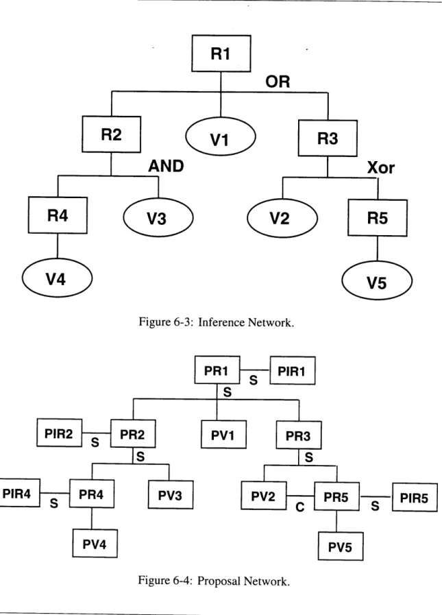
6.3.1 CONGEN inference network 6.3.2 Similar Recommendations . 6.3.3 User input ... 6.4 Conflict Mitigation ... 6.4.1 Rationale Dependencies . . 6.4.2 Conflict Detection ... 6.4.3 Conflict Causes ... 6.4.4 Conflict Resolution .... 6.4.5 Conflict Prevention . . .. 144 . . . . 144 . . . . 146 . . . . 147 . . . . 15 1 . . . . 15 1 . . . . 152 . . . . 158 . . . . 162 . . . . 164 . . . . . 166 . . . . 167 . . . . 170 . . . . 172 . . . . 172 6.5 Chapter Conclusions ... ... 7 Illustrative Example 7.1 Chapter Introduction ... ... 7.2 Bridge Design . .. .. . . .. . .. . . . .. . . . . 7.2.1 Single Designer Design Rationale Capture . . . . 5.4 5.5 5.6 129 130 131 138 142 173 174 174 175 175 ...
CONTENTS
7.2.2 Multiple participants conflict mitigation ... 182
7.3 Implementation . ... . . .. . . . . .... . 205
7.4 Chapter Conclusions ... . . . . ... . . 208
8 Conclusions 209 8.1 Introduction .. . . ... . . . . . . 209
8.2 Benefits of the Model . . . ... . . . ... . 211
8.3 Contributions ... . . . . . . 215
List of Figures
2-1 First Proposal of Geotechnical Engineers . ... 37
2-2 Proposal Hierarchy of Geotechnical Engineers . ... 38
2-3 Selection of structural form and material for Sollecks Bridge - Part I.... 43
2-4 Selection of structural form and material for Sollecks Bridge - Part II. .. 45
2-5 The Design Process . ... 49
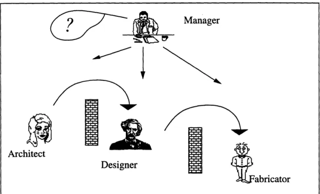
3-1 Over the wall engineering ... 60
3-2 Computer-based view of cooperative product development ... 61
3-3 Organizational view of DICE ... .... 64
3-4 A Semantic Network. ... 72
4-1 Comparison of Design Rationale research efforts. . ... 81
5-1 DRIMS components (the graphical notation used is the OMT model [Rumbaughetal., 1991]). ... ... 92
6-1 SHARED-DRIMS Conceptual Organization with two designers and a negotiation workspace ... 148
6-2 SHARED-DRIMS Architecture. . ... ... 149
6-3 Inference Network ... 157
LIST OF FIGURES
6-5 SHARED-DRIMS: Design Intent Window with both structured and
un-structured representation. . ... ... 163
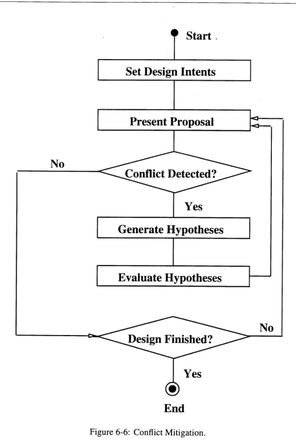
6-6 Conflict Mitigation. ... 165
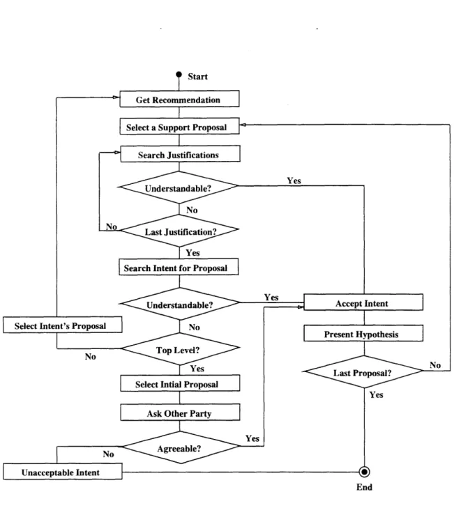
6-7 Hypothesis Generation. ... 171
6-8 Versions for resolving conflicts with design 1 -each version of the conflict resolution is a entry key for the graph. . ... 173
7-1 Improved process for selecting the form and material of the Sollecks Bridge 176 7-2 Initial proposals presented by the structural engineer and SHARED-DRIMS 177 7-3 C++ code representation of a generic recommendation . ... 178
7-4 Rule for designing a bridge ... ... 179
7-5 Proposal and contradicting proposal combined . ... 181
7-6 Proposals presentation for selecting the bridge material ... . 183
7-7 Type of material in the bridge artifact . ... 184
7-8 Bridge artifact as a place holder . ... ... 184
7-9 Bridge artifact with a material in its structure . ... 185
7-10 Bridge artifact with material, sub-systems and components in its structure 186 7-11 Version tree of the bridge artifact ... .. 187
7-12 Initial proposal by SHARED-DRIMS to select the bridge structural form . 188 7-13 Rule for developing a two span bridge . ... 189
7-14 SHARED-DRIMS: Main Window with the project participants... 190
7-15 SHARED-DRIMS: Main Window with the project intents, the product hierarchy of the bridge, the proposal hierarchy of the designer, and a rough sketch of the design . .... ... .... ... ... .... ... 191
LIST OF FIGURES
7-17 Display of the two span bridge in the non-manifold geometric modeler
(GN OM ES) . . . . 193
7-18 SHARED-DRIMS: Violation Notification Window with the contractor rationale for rejecting prefabricated concrete as the material for the bridge. 195 7-19 Material proposals presented by the different participants ... . 196
7-20 SHARED-DRIMS: Violation Notification Window with the rationale of the contractor and the environmental engineer which makes the usage of a central pier conflicting ... . 197
7-21 Display of the single span bridge in the non-manifold geometric modeler (GNOMES) ... 198
7-22 Display of the three span bridge with vertical piers in the non-manifold geometric modeler (GNOMES). . ... ... 199
7-23 White Shared-Board for inter-machine communication . ... 199
7-24 E-mail window for sending messages to other participants . ... 200
7-25 Video window for visual inter-participants communication ... . 200
7-26 Complete screen with all the inter-participants communication tools . . . 201
7-27 Form proposals presented by SHARED-DRIMS and the structural engineer 202 7-28 Rule set by the contractor limiting the size of the members ... . 203
7-29 C++ code for linking artifacts ... 203
7-30 C++ code for checking constraints ... .. 204
7-31 C++ code for running the inference engine . ... 205
7-32 SHARED-DRIMS: Violation Notification Window with the rationale of the geotechnical engineer which makes the usage of a vertical piers conflicting. 206 7-33 SHARED-DRIMS: Ask Window which informs that the system could not find any conflict with the new design. . ... 207
LIST OF FIGURES
7-34 Display of the three span bridge with inclined piers in the non-manifold geometric modeler (GNOMES). . ... ... . . . . . . 207
Notation
* Phorizontal is the soil pressure on the horizontal direction.
* Pvertical is the soil pressure on the vertical direction.
* q is the angle of internal friction of the soil. Its tangent is equal to the coefficient of intergranular friction, which can be determined by appropriate laboratory tests.
* c is the coefficient of earth pressure at rest.
* tan2 is the tangent of an angle to the power of two
* A = { (ti, ai, vi) }* is a set of symbols. Each of these symbols are explained in the text of the thesis as they occur.
* (Designer, oid, A, M, R, C) is an class description with a class identifier, sets of
attributes, methods, relationships, and constraints.
* V is the for all symbol.
* E is the in a set symbol.
* 3 is the exists symbol.
NOTATION
* : is the such that symbol.
* . is a reference symbol. It implies the part of an object. For example, in rm,.[elb], .
implies that e or b are part of re,.
*
[] is a reference symbol which implies grouping. For example, in rem .[e b], [] impliesthe set of e or b that are part of rtm.
* =j is the implies symbol.
* - is the equivalent symbol.
* de(ie, C) is a justification called dt which is linked to an it intent in a C context. * O(i+ I Iplant+1 lat+l) is an operator called 0 which takes as argument it+l or plant+1
or at+1.
I is the or symbol.
Chapter 1
Introduction
Managing ... conflicts typically involves complex phenomena,
mul-tiple issues, and institutions having differing objectives and re-sponsibilities. The synthesis, understanding and communication of relevant data and the identification and evaluation of possible solutions with the aid of analytical and computer models is often proposed, and occasionally accomplished, to support one or more participants in a conflict management process.
Daniel P. Loucks, [Loucks, 1989]
1.1 Overview
The development of large scale engineering systems requires the collaboration of numerous specialists. These specialists may reach conflicting decisions as a result of their different perspectives on a given problem. These perspectives are revealed in their design rationale. However, each designer brings considerable knowledge and performs a great number of tasks to come up with a design. If all of this information were available to all the designers,
1.2 Research Problem
each one would be overwhelmed with data. Thus, a computer system is needed that will help designers to record and use information effectively from the whole group to achieve effective conflict mitigation.
Section 1.2 introduces the problem for the Architect-Engineering-Construction (AEC) industry. Then, in Section 1.3, the motivations for undertaking this research are presented. The goals sought and the scope of the research are presented in Section 1.4. The approach followed in the research is then described in Section 1.5. Finally, Section 1.6 outlines the organization that will be followed in this dissertation presentation.
1.2 Research Problem
The development of large-scale engineering systems requires the collaboration of numerous specialists. During such a development process, up to as many as three hundred different specialty design firms, suppliers, and contractors may participate. This participation results in interactions among many different types of professionals. Their decisions reflect their different perspectives on a project, and these different perspectives typically lead to many conflicts. These conflicts, if not resolved early, create more expensive designs, delays in the schedule of the design-construction process, and compromises in the final product. Avoidance of these conflicts is typically accomplished with overly conservative designs, when applied to physical or functional objects which interact. In the next paragraphs, these various problems will be illustrated with two case studies.
The Boston Central Artery/Tunnel is a 7.8 billion dollar example of a large-scale engineering project [Sheridan, 1993]. It may eventually involve more than 150 main organizations during both the design and the construction phases. These organizations may
1.2 Research Problem
work on the same or different parts of the project, and they must interact with each other. It is these interactions that exemplify the kinds of situations that can produce conflicts.
The design of the Central Artery segment that crosses the Charles River has generated many conflicts [Sheridan, 1993, Project, 1994]. There have been over 80 alternative layouts suggested for that crossing over a period of two and a half years. One of the reasons for such a large number of alternatives is that some of the participating organizations have recommended alternatives that have already been ruled out by other organizations. For example, the community organizations rejected the use of a bridge for the crossing, as suggested by the designers, and recommended the use of a tunnel. However, a tunnel had previously been rejected by the designers because it was not economical and involved large risks during construction. Then, after several iterations, the community organizations and the designers started exploring a combination of bridge and tunnel for the crossing. If the community organizations had had access to the information about the reasons for the designers' rejecting the tunnel, they could have started exploring other possibilities sooner instead of spending the time in a design alternative that was unsatisfactory from the design point of view both economic and ease of construction. Thus, some of the inefficiencies of the process stem from one group's lack of information about other groups' objectives and reasons for rejecting or accepting a given alternative, such information is termed as "design rationale".
This lack of information about organizations' design rationale can be attributed to deficiencies in their channels of communication. They use blueprints and specifications for intra and inter-organizational communication. Some of the more advanced organizations have begun to use CAD files for their internal communications. These communication mechanisms (blueprints, specifications, and CAD files) deal only with the characteristics
1.2 Research Problem
of the artifacts. They do not transfer information about the objectives and the reasons for accepting or rejecting a design alternative. While such iniformation is important to subsequent decision-making, it can only be surmised from these communications.
The failures to communicate are not limited to the designers of the Boston Central Artery/Tunnel. NYC's Bureau of Water Pollution Control has also recognized the problems due to the lack of communication about objectives. The Bureau has issued a handbook about conflict based on its experience during the upgrade of nine sewage treatment plants [City of New York Bureau of Water Pollution Control, 1980]. It developed a list of 2200 potential conflicts that should be avoided during the design of any of the plants. Most of these conflicts are based on the needs of different specialties to satisfy objectives that have not been explicitly stated. For example, where durability is the objective, the Bureau asks: 1) "Do the specifications provide for stainless steel angles where durability is required?"; 2) "Does the design provide for use of stainless steel railing to better withstand corrosion?"; and 3) "If data indicates fluctuating ground water levels, does design call for treated timber piles?" The specificity of these questions is impressive; and the common underlying theme is an explicit identification of issues that may help to avoid conflict. The handbook emphasizes the importance of learning from the experience of past design projects as it resulted on a conflict decrease on the development of sewage treatment plants. A study of the handbook suggests the value of a system that provides for capture, storage, and use of information from previous designs. These two cases - Boston Central Artery/Tunnel and the NYC's Bureau of Water Pollution Control - show the importance of communicating the design rationale (objectives and reasons) of the individual participants in the project
and the rationale for its evolving overall plan.
1.3 Research Motivation
between the different participants has often lacked reference to the decisions and the reasoning that shaped the design, that is, reference to the design rationale. The AEC industry can benefit on two fronts from representing the design rationale explicitly: first, there will be savings in the life-cycle cost due to more effective communication, coordination and negotiation; and second, the quality of the final product will increase because the requirements or design intents are readily accessible for review.
1.3
Research Motivation
Nowadays, the computer plays an important role in almost every industry. In the AEC industry this role may be changing from one that emphasized computer graphics and numerical analysis to one of management of information [Gantz, 1989]. Traditionally, designers have used a wide range of knowledge and have performed a large number of tasks in selecting the characteristics of an artifact. If this information is made available to all designers working on a project, individual designers could become overwhelmed with data and its complexity. Thus, there is a pressing need for systems which help designers capture, interpret, and easily utilize this data.
As discussed in the previous section, design rationale can serve as an important basis for conflict mitigation. However, the information generated during the process of recording design rationale may be overwhelming. In keeping with the trend in information management systems, an intelligent support tool for use of this information can be perceived as an essential part of a conflict mitigation system. Here, the computer is used as an assistant that will monitor the design rationale as it is generated and will detect any potential conflict with other specialists' decisions.
1.4 Research Goals and Scope
This research is presented within the broader context of a set of support tools for representing and using design knowledge in a collaboritive environment. It is a component of research on DICE (Distributed and Integrated environment for Computer-aided Engineering) [Sriram and Logcher, 1993]. The DICE framework is a set of computer-based tools for supporting design activities. These new tools are able to provide some of the design rationale stored in their knowledge base, to store the information in a persistent form and to allow for future modifications by other tools. The availability of such environments, the potential for capturing design rationale, and the pressing need for conflict mitigation have motivated this research.
1.4 Research Goals and Scope
The goals of this research are to represent, use, and communicate design rationale for conflict mitigation in a collaborative environment. To this end, the research is aimed at developing: an ontology for the design rationale; and a management system to capture,
interpret, and easily utilize that ontology.
The model provides the constructs for defining all the elements that are involved in the design rationale. It not only helps to record the designed artifact itself, but also the proposals that introduced it, the objectives it is trying to achieve, and the justifications for selecting it.
The system for conflict mitigation addresses two critical research problems: first, design rationale has to be captured from humans or computers involved in the design of the project; and second, a system needs to reason about the captured rationale in order to provide support for conflict mitigation in a collaborative environment.
1.5 Research Approach
The scope of the system reasoning will be to automatically resolve known conflicts when solutions are available in its knowledge base, and to provide hypotheses about the reasons for unknown conflicts. These hypotheses, once verified by the designer, permit better coordination and negotiation during conflict resolution. This, in turn, will enhance communication during the design process and consequently increase the productivity of the AEC industry.
The scope of testing of both the system and the model is limited to small-scale problems dealing with conceptual design. The approach is potentially extensible to apply throughout the life-cycle of large scale design-construction problems.
1.5 Research Approach
In order to capture the design rationale for conflict mitigation, the design process and its evolution must be analyzed. With this perspective in mind, three case studies in design were performed (see Section 2.2). Based on these cases, a set of requirements was developed for a design rationale framework for conflict mitigation system. Then, a survey of current models or systems that capture design rationale was performed. A Design Recommendation-Intent Model (DRIM) was proposed as an ontology for representing the design rationale. SHARED-DRIMS was then developed as a system for conflict mitigation through the capture and management of the design rationale. After the model was developed, three more case studies were performed to validate it and to provide the test-bed for SHARED-DRIMS.
1.6 Thesis Organization
1.6 Thesis Organization
* Chapter 2 presents the background information for the research described in the
remainder of the thesis. The design process is analyzed from the conception of a need to the functioning of an artifact. It describes the six case studies performed during the research to create the system requirements and to validate the system. The set of requirements for a conflict mitigation system is presented.
* Chapter 3 outlines the use of computer supported collaborative engineering in terms
of the DICE framework, with a focus on the overall architecture and organizational view. It explains the methodology for information modeling combining object-oriented methodology and its use in the representation of semantic networks. Finally, the SHARED model is presented, providing the basis for the representational structure of the DRIM model.
* Chapter 4 provides a survey of related work on design rationale with focus on the
number of participants that the models support and the computer involvement on providing part of the rationale. In addition, a survey of related work on conflict mitigation is presented with a grouping of user-driven models and automated models. The user-driven models or systems take a set of options presented by the designers and points out the best one. The automated systems provide the options to the designers, but does not necessarily interact efficiently with them.
* Chapter 5 describes a model which incorporates the different elements of design
rationale. This chapter presents the DRIM primitive classes, the DRIM relationships, the process of design with the DRIM objects, and the development of design rationale traces.
1.7 Conclusions
* Chapter 6 presents the functionality of the system that helps in the capture and
utilization of design rationale for conflict mitigation. Thie different sections of this chapter cover the SHARED-DRIMS architecture including the base modules and the design rationale modules. Other sections present the conflict mitigation process with conflict detection, the generation of hypotheses for the causes of the conflicts and the hypotheses communication.
* Chapter 7 illustrates the system at work through an example. The Sollecks River
bridge example is described, focusing on the selection of the structural material and form. The conflict mitigation between the different participants in the process is provided.
* Chapter 8 summarizes the main issues discussed in the thesis. It also discusses
future research issues.
1.7 Conclusions
The AEC industry faces a problem in terms of mitigating conflict. This problem arises from the collaboration of many specialists with different perspectives, which conflict in the realization of the project. One hypothesis is that these conflicts could be mitigated by making the design rationale of the participants available to everyone participating in the process. However, this information can be overwhelming for the designers, and therefore the need for systems that help designers capture and use that information must be addressed.
Chapter 2
Requirements Analysis
The first step in developing anything is to state the requirements. This applies just as much to leading-edge research as to simple programs and to personal programs, as well as to large team efforts.
Rumbaugh, Blaha, Premerlani, Eddy and Lorensen,
[Rumbaugh et al., 1991]
2.1 Introduction
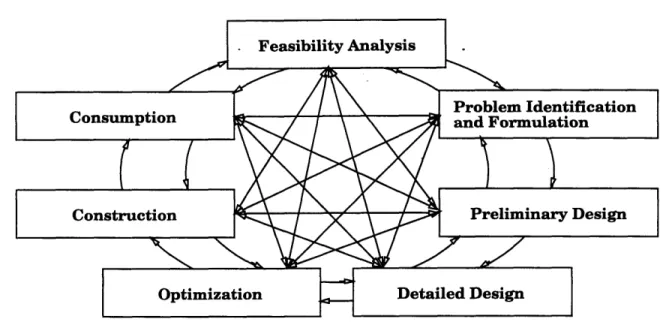
Engineering design and construction are activities that humans have performed since early times. However, these areas have not been perceived as systematic processes which could be subject to comprehensive analysis and improvement until the past few decades. The understanding of the design process is important for representing and capturing design rationale. Thus, the use of case studies about design will be relevant in presenting participant's interactions, information, and tasks. Section 2.2 describes six case studies performed during the research to create the system requirements and to validate the system. Section 2.3 presents a general description of the design process, from the conception of a
2.2 Case Studies
need to the functioning of an artifact, based on the case studies and the design literature. Section 2.4 presents a set of requirements for a conflict mitigation system. Finally, Section
2.5 provides a summary of this chapter.
2.2
Case Studies
The understanding of the design process is important for representing and capturing design rationale. The use of case studies about design sheds light into the interactions among participants, the type of information used in design and how they are used. Lastly, it shows the different steps performed by the designers. The following sections present six case studies. These examples are as follows: the selection of an earth retention system, the design of a valve, the design of a flume, the structural design of a building, the structural design of a bridge, and the selection of a river crossing.
2.2.1 Earth Retention System Design
A developer and an architect of a building hire a construction consulting firm to assist in the selection of an earth retention system [Becker, 1989]. The building has two levels of parking extending 24 feet below the existing site level which is at an elevation of 57.0
feet. The design of the earth retention system needs to take into consideration the fact that the building is designed to be located in a site where an existing five-story brick building, which is very close to the new building, needs to remain at its current location. In addition, the designer of the retention system has to consider the potential effects of a river that passes close to the project site.
Based on these facts, the construction consulting firm has been asked to provide its recommendations for the earth retention system after completing the following process:
2.2 Case Studies
1. State the design requirements.
2. Present the alternatives that satisfy the requirements.
3. Present the reasons that explain how the alternatives satisfy the requirements.
4. Analyze the reason presented for each alternative.
5. Select the alternative that is the most appropriate.
With this process in mind the consultant starts by presenting six of the requirements sought with the earth retention system. These requirements are to: 1) minimize the cost of the earth retention system; 2) minimize project completion time; 3) increase reliability of the earth retention system; 4) control groundwater flow; 5) resist soil and water pressure; and 6) reduce the impact on the adjacent building. The developer and the architect provided the consultant with two alternatives which may satisfy the requirements: 1) Z-sheeting piles, and 2) structural slurry wall. This scenario shows that designers start with a set of requirements that they need to satisfy. It also shows that for certain requirements, such as minimize, increase, and reduce, comparisons between alternatives are needed. In this particular design, the alternatives taken were only two. Now, the consultant searches for justifications that establish a relation between the alternatives and the requirements. These justifications are:
Alternative I: Z-Sheeting
1. REQUIREMENT: Minimize the cost of the earth retention system
* Z-Sheeting can be provided by many capable and established suppliers. * Z-Sheeting requires no waterproofing.
2.2 Case Studies
* Z-Sheeting needs careful installation for system to work as expected.
2. REQUIREMENT: Minimize project completion time
* Z-Sheeting can be provided by many capable and established suppliers.
* Z-Sheeting may require expensive underpinning of adjacent structures. * Z-Sheeting needs careful installation for system to work as expected. 3. REQUIREMENT: Increase reliability of the earth retention system
* Z-Sheeting can be provided by many capable and established suppliers. * Z-Sheeting is commonly used in this area
* Z-Sheeting may require a clear driving path 4. REQUIREMENT: Control groundwater flow
* Z-Sheeting prevents water table lowering.
* Z-Sheeting provides a water seal both temporary and permanent
5. REQUIREMENT: Resist soil and water pressure
* Z-Sheeting resists the active earth pressure given by the formula
Phorizontal = Pvertical tan2(450 - 4/2) - 2c tan2(450 - 0/2)
6. REQUIREMENT: Reduce the impact on adjacent building
* Z-Sheeting may require expensive underpinning of adjacent structures.
* Z-Sheeting can be provided by many capable and established suppliers. * Z-Sheeting produces settlement-causing vibrations during installation.
* Z-Sheeting prevents water table lowering.
Alternative II: Structural Slurry wall
2.2 Case Studies
* Structural slurry wall can be provided by many capable, established suppliers
* Structural slurry wall requires no waterproofing.
* Structural slurry wall can be used as permanent foundation wall.
* Structural slurry wall has the highest cost of all the alternatives per linear foot.
2. REQUIREMENT: Minimize project completion time
* Structural slurry wall takes a lot time to construct due to low production rate
3. REQUIREMENT: Increase reliability of the earth retention system
* Obstruction on the work area does not cause major problem
* Structural slurry wall can be provided by many capable, established suppliers
4. REQUIREMENT: Control groundwater flow
* Structural slurry wall prevents water table lowering.
* Structural slurry wall provides a water seal both temporary and permanent
5. REQUIREMENT: Resist soil and water pressure
* Structural slurry wall resists the active earth pressure given by the formula
Phorizontal = Pvertical tan2(450 - 0/2) - 2c tan2(450 - 0/2)
6. REQUIREMENT: Reduce the impact on adjacent building
* Structural slurry wall prevents water table lowering.
This itemized account of alternatives, requirements, and justifications shows that de-signers use justifications as the linking elements between design artifacts and requirements.
2.2 Case Studies
The justifications are used as supporting arguments to the hypothesis that an alternative satisfies the requirements. In this design case, the designer analyzes each of the reasons re-lated to the requirement. From this analysis, the professional determines that the Z-sheeting has a lower probability for meeting the requirement of reducing the impact on adjacent building while it has a greater chance of satisfying the requirement of minimizing the cost. Similarly, the structural slurry wall satisfies the requirement of reducing the impact of adjacent structures better, while it is not good at satisfying the reducing cost requirement.
After the designer performed the analysis s/he gives the highest priority to the goal of reducing impact on adjacent buildings. The reason given for this ranking is that the impact on adjacent buildings is a high legal risk that could cause the project to be stopped. In addition, the cost of repairing adjacent buildings was difficult to estimate until the problem occurs, since the documentation and the specification of existing buildings were not readily available. By designers providing a higher priority to a requirement, they are saying that not all the requirements are as important. Some of the requirements are needed while others are good to have.
Based on the priority of the goals and the analysis of the alternatives, the designer selects Alternative 2 (Structural Slurry Wall). One of the justifications that supports this decision is the assumption that this earth retaining system does not produce settlement-causing vibrations during installation. The second justification is that the structural slurry wall is as good as the Z-sheeting alternative in preventing the water table lowering thus achieving good groundwater control.
On the other hand, the structural slurry wall presents deficiencies in achieving the goal of cost minimization. This goal received low ranking in the designer priority list and did
2.2 Case Studies
not have great influence in the decision. Thus, the rationale included: the requirements of the design, the assumptions made during the design process, the two alternative designs, the reasons of each alternative, and the selection process of choosing one design over the other based on the reasons and the ranking of the requirements.
This design case shows the dynamic structure of the decision process. A set of requirements that at the beginning had equal importance have now been ranked. This ranking in turn can affect the decision of selecting one alternative or another. Thus, it is necessary to capture the shift in importance of the elements involved in the decision. In the above design case, if construction cost were the only driving factor in the decision, the selection of the system would have been scheme 1 (Z Sheeting).
After a solution alternative has been selected, a record has to be maintained not only of the selected alternative but also of the process by which this alternative was selected together with all the other alternative solutions considered in the decision problem. In the above design case, schemes 1 and 2 have to be stored along with all the explanations given in the previous paragraphs. When a question about certain requirements arise, the decision process can be searched and explanations for the problem can be found.
For example, the owner of the project was given certain preliminary cost estimates of the project before the design of the complex started. Then, after two months, when the earth retaining system has been selected, the owner receives new cost estimates. These new estimates vary considerably from the previous one and s/he asks why the estimates are so different from the initial ones. In this case, the architect needs to give reasons for the variance. If the project team had captured all the information described previously, they need search only for the decisions associated with project cost.
2.2 Case Studies
2.2.2 Valve Design
An entrepreneur assigned a design team to design an artifact that would redirect and stop the flux through a network of tubes within a larger device [Kumar, 1992]. This artifact would be used in laboratories where different liquids and gases circulate through a network of tubes. This case study presents the different steps that are performed from the study of market needs to manufacturing process. It also highlights some of the main issues raised during the design process, i.e. justification of cost and lack of achieving a requirement.
This case study was performed and documented for this dissertation research. However, it cannot be included in this dissertation because the designer was seeking a patent and the details of the design could not been given out. Only the results form the case study will be presented on the following paragraphs.
Summary
The scenario that was studied demonstrated the dynamic structure of the design-decision process. The following is a summary of what transpired in this scenario:
* the requirements for the design were elaborated at different stages of the design. Exploration and discovery comes together since some of the ideas developed as the design proceeded. The designers never started with the idea of having different markets to which the design could be sold such as biological industry and chemical industry. That idea evolved as the design developed.
* designers had limited knowledge and needed the interaction and communication with other professionals. For each of the material types, the designer called on other sources for information such as a ceramic manufacturer, with whom he queried the manufacturability of the design.
2.2 Case Studies
* designers used prototypes to clarify concepts. The physical artifact was able to demonstrate how the concepts will work under real world conditions.
* various design alternatives were arrived at that could satisfy the requirements to
certain degrees.
* within the realm of the requirements the rationale of each design were explored.
* each of the requirements for the design was given a priority level. This ranking in
turn affected the decision of selecting one alternative design over the other.
* designers used concepts from other fields based on similarity of properties. In this case, the designers tested the use of ionic coating because of its success in pumps.
2.2.3 Flume Design
This case refers to the design of a flume to be used for testing the effect of soil erosion in the contamination of river basins [Andrews, 1993]. The design has to allow for the settlement and suspension of the soil particles. This is necessary to determine the type of flow that causes erosion of naturally sedimented soils. In this design, the principal professionals involved are three geotechnical engineers, one of whom was in charge of constructing the flume (the contractor) and another was in charge of testing the erosion theory (the user). All the geotechnical engineers are responsible for designing the flume so that the relationship between the effective stress-strength parameters of sediments and the critical shear stress required to initiate erosion can be established. The constructor is responsible for constructing the flume so that it satisfies the geotechnical engineers' specifications. The user is responsible for performing the tests required and demonstrate the theory. As this case shows, the constructor's work depends on the geotechnical engineers' and the geotechnical engineers' work depends on the tests that the user wants to perform. This
2.2 Case Studies
interaction requires considerable coordination and communication, in order to achieve the desired requirements. Below, the reasoning process of the geotechnical engineers is
recorded.
The geotechnical engineers need to establish the relationship between the effective stress-strength parameters of sediments and the critical shear stress required to initiate erosion. To achieve that goal, they present a proposal that contains -as a recommendation-a plrecommendation-an with the following gorecommendation-als: 1) use of mrecommendation-arine clrecommendation-ay, specificrecommendation-ally Boston Blue clrecommendation-ay; 2) perform erosion tests on a deposited bed; and 3) perform strengths tests on the same bed. The justifications of using such a plan are: 1) it proposes the use of a cohesive sediment that is important for the contamination that may result if it is eroded; 2) it allows the investigation of erosion on normal and uniform bed sediments; and 3) it allows the measurement of the strength of the soil under different stresses. Figure 2-1 shows the representation of this first proposal. Figures 2-2 shows the proposal hierarchy as developed by the geotechnical engineers.
The proposals introduced the use of a linear flume at the beginning. As the design progressed, the flume was changed to a linear flume with re-circulating pump and finally to a rotating annular flume. All these proposals were introduced as consequence of new intents evolving as decisions were made. One observation made by the designers was that these new intents and proposals had some relationships with the old information. The concept of linear flume was developed since water was needed to run constantly through the flume. However, there were practical problems with it. The water condition at the ends would have been different from the water condition on the flume. This problem rule out the use of linear flume. Thus, a new concept was sought. This concept was the use of a rotating annular flume. This new concept was then evaluated with respect to all the
2.2 Case Studies
intents that the linear flume needed to satisfy. Here, it can be seen that the design rationale was used for defining the context of new concepts. Design rationale would be also useful for defining why a rotating annular flume was selected. Without that information, other participants on the project may arrive at wrong conclusions about the need of such a flume.
It was also found in this case study, that participants requested design rationale information when they were negotiating changes. For example, one of the geotechnical engineer proposed a re-circulating pump to make the water run through the flume. However, one of the other engineers opposed this decision. They entered into a negotiation process about the use of re-circulating pump. During that process, they presented reasons against and in favor of the decision. One of the reason in favor was that re-circulating pump would allow the modeling of the actual length of the river. This reason implies that modeling the actual length of the river was an intent that needed to be satisfied. One of the reason against the use of re-circulating pump was that it would destroy the aggregate particles. This reason in turn implies that accurately modeling the particles on the river was another important intent. In both cases, the geotechnical engineers presented intents that need to be satisfied in order to achieve a satisfactory design. The way they resolved the conflict was by selecting a solution that satisfied both designers. However, this resolution was only achieved when the intents were explicitly stated for everyone to use. Thus, the explicit presentation of intents would allow a quicker resolution of the conflicts.
2.2.4 Building Design
A structural engineer has to design a one story building with a basement and structural capacity for supporting 2nd and 3rd floor future additions. The structural engineer interacts with an architect, a contractor, the owner, and a mechanical engineer during the structural
2.2 Case Studies
cj
0c
0
2.2 Case Studies LL 0> 0= 0 0d 0 Cl 0c
2.2 Case Studies
design of the building. These interactions lead to many changes which in turn lead to conflicts among the participants. In this write up, the interactions are documented and the reasons for such interactions are explained.
1. The present roof is kept level to provide a floor for the future additions to the building. However, this design recommendation was not achieved until a round of negotiations between the architect, the owner and the structural engineer. Usually the steel used for the roof is sloped to get better drainage and the architect could have used tapered insulation to achieve this. The use of a flat roof was a compromise between good drainage and ease of construction for the next construction phase.
2. An existing tunnel posed a number of problems for architectural layout, structural scheme and mechanical ductwork space. The structural framing scheme was revised a number of times to work around the tunnel. First, the owner and architect thought that they could keep the tunnel without the building having access to it. Based on this, the architect changed the floor plan of the building so that there was no interference with the tunnel below. The owner then required that the building have access to the tunnel. The architect changed the layout to adapt to this new requirement. In the interaction between the architect and the owner, the need to share requirements across disciplines is shown. The architect includes the need to have tunnel access into his/her requirements. With that new requirement, the architect could produce a satisfactory solution to both his/her and the owner's requirements. In conclusion, conflicts can be mitigated if requirements are explicit and sharable.
3. The study made by the structural engineer revealed problems with the structural frame and the location of the tunnel. In addition, the contractor estimated that the access to the tunnel would increase the cost of the building significantly. Then, the
2.2 Case Studies
owner decided to relax this requirement. This decision also allowed for a better floor plan from the architect point of view.
4. Framing scheme was coordinated with the architectural designers to obtain somewhat even bay spacing in some areas and a big open space in one area. The reason for even bays was constructibility while the open space was based on aesthetics. The use of a big open space posed some problems. Location of a column was revised several times to fit the architectural layout. Another column was eliminated resulting in the need for a W30 beam, which in turn caused low headroom for mechanical ductwork. The mechanical engineers had to work around this beam and had to change their design accordingly.
5. The architect wanted to eliminate a ledge in the basement which was standing from an earlier construction. However, due to the cost of underpinning an existing stairwell footing, a compromised design was achieved in which the ledge stayed and the architect incorporated it into the architectural layout of the basement area.
6. The construction manager was surprised to know that steel weight came in at 10 lbs/sf instead of 6.5 lbs/sf that he had budgeted at the beginning of the project. He had not anticipated that designing for the future additions would involve such a great increase in steel members' weight. This change produced an increase on the cost of the project.
The process followed is similar to other projects. The project begins with schematic drawings. The structural engineer has to prepare a framing scheme (beam, column, etc.) with approximate sizes based on experience from other jobs. This activity lasted around two days with a lot of conversations over the phone. Contact was not possible at times and the structural engineer had to wait for the architect to get back to him. Then after schematic
2.2 Case Studies
design had been performed, the architect would get back to the owner and the mechanical engineer. Some of the problems that arose were solved by phone and fax machines. Once the schematic was checked, the structural engineer went on to the detailed design. At this time, the steel is pre-bid based on rough quantity and price/unit of quantities because scope is defined and fast delivery is very important. This posed a serious problem because of the stage of the design. In that case the structural engineer was conservative and ordered steel that was not very likely to change during the early stage of the process. That same philosophy was used for detailed design. Designers performed detail design on the parts of the design that are not very likely to be changed. The areas that are likely to be changed always go back and forth several times with some down time for the need to contact the people that are involved in the decisions.
2.2.5 Bridge Design
This case refers to a bridge over the Sollecks River located in the Olympic peninsula in northwest Washington [White et al., 1972]. In this case, the focus was on the process of selecting the structural form and the material of the bridge with the interactions of the structural engineer, the environmental engineer, the geotechnical engineer and the contractor. The case has been augmented with information obtained from Dr. Ashok Gupta [Gupta, 1993] when the information could not be found in White et al., 1972.
This case starts with the geotechnical engineer performing some preliminary soil testing (see Figure 2-3). During his investigation he determines that the soil has good normal force resistance and recommends the usage of piers near the base or ends. Then the structural engineer takes that information to select the form and material of the bridge. She decides to use prestressed concrete and a two span bridge with a vertical support and end foundations.
2.2 Case Studies
Subsequently, the structural engineer checks with all the other professionals involved in the project, namely the environmental engineer, the geotechnical engineer and the contractor (see first loop in Figure 2-3).
After receiving and reviewing the drawings, the environmental engineer rejects the design due to problems with the central pier. She argues that the fish life and river flow will be affected during construction. On one hand, the geotechnical engineer accepts the design. On the other hand the contractor rejects the design due to problems with the construction of the central pier and the usage of prestressed concrete. He recommends the removal of the central pier and the usage of steel girders instead of prestressed concrete. The structural engineer then uses the feedback obtained from the other participants to revise her design.
She then selects a prestressed concrete single span bridge. Again she checks with all the participants (see second loop in Figure 2-3). She informs the contractor that steel is not a viable solution since it violates objectives in her domain such as low maintenance cost for the bridge. Had the contractor had access to this information, this interaction could have been avoided. At this time both the environmental and geotechnical engineers accept the design. However, the contractor still rejects the design due to the lack of construction facilities for building such a long single span bridge using prestressed concrete. He recommends the use of prefabricated prestressed concrete and suggests that the structural engineer change the structural form of the bridge. This interaction could also have been avoided if the structural engineer had access to the contractor's reasons for rejecting the long pier the first time.
With this information, the structural engineer selects prefabricated prestressed concrete as the material and a three span bridge with two vertical piers as the structural form (see
2.2 Case Studies 4 . 0 00~ 0. C1 SO w U(U anai' U~ Ea a) * 0 E r-a- t >~ E00 A a)~a SoB8 *6LU d 0 .0 r U -II "----·-a) A uO > >, 00g 2 La) .a' a. co U ( 0 t Oa.9 u O na) (U0La . fa.0 a 2.0a~a) U CL ~04 .0V GnM · ~a U,(Uo a) *m (Ua a~ua C, 0 a), an 0 (U > a) . r. 0~ (A an T m > a a~ 0 ...I ... 0 * a..i 0. 0r ~ .0 U *c US I 0 a) 'U 0. 0 9~ · ·· · ·- ·... ~0 a) .0 a) · · 111··· ... ]...4... ...p ... 4... w. ... .... .... .. .... r Y
A
2.2 Case Studies
Figure 2-4). She checks one more time with all the participants in the project (see first loop in Figure 2-4). At this time both the environmental engineer and the contractor accept the design. The geotechnical engineer rejects the design due to the shearing forces that may develop in the sloped rock. He recommends the usage of piers at the center or at the ends. The structural engineer revises the design and informs the geotechnical engineer that piers cannot be set on the center or ends. The geotechnical engineer then suggests that the piers be located perpendicular to the slope.
The structural engineer receives that recommendation and selects a three span bridge with two inclined supports. She again checks with all the professionals (see second loop in Figure 2-4). All the professionals accept the design and the structural engineer proceeds with the detailed design.
As this case demonstrates, there are some deficiencies with the process. First, the process takes a long time to deliver. Second, the process may produce poor quality products. In terms of delivery time, there are three main deficiencies. First, some information may be lost, such as information regarding the reasons why a specific recommendation was made. Second, the participants will have to regenerate the information lost if they are asked for it. Third, the process has interactions that could be avoided if information about why a design has been rejected or why a recommendation is made is available. For example, the selection of a single span bridge would not have been presented as an alternative, had the structural engineer known the reasons for the rejection of the long pier by the contractor. In terms of the quality, there is one main problem. Constraints set by participants through assumptions may be violated. Violations may go undetected during the initial stages and may be detected at a later stage. The changes at later stages will be made under strong time and cost constraints. Designers will tend to focus on the problem area and disregard the
2.2 Case Studies co *.b c1 0 -o 0 O u (" -s
2.2 Case Studies
overall optimization of the product.
2.2.6 River Crossing Selection
The Boston Central Artery/Tunnel is a 7.8 billion dollar example of a large scale engineering project [Sheridan, 1993]. It involves more than 150 primary organizations during both the design and construction phases. These organizations may work on the same or different parts of the project, but they must interact with each other. These interactions bring about conflicts that must be resolved.
The design of the Boston Central Artery/Tunnel segment that crosses the Charles River has generated a lot of conflicts [Sheridan, 1993, Project, 1994]. There have been over 80 alternative layouts for that crossing over a period of two and a half years. One of the reasons for such a large number of alternatives is that some of the participating organizations recommended alternatives that had been ruled out by other organizations. For example, the community organizations rejected the use of a bridge for the crossing as suggested by the designers and recommended the use of a tunnel. However, a tunnel had previously been rejected by the designers because it was uneconomical and involved large risks during construction. Then, after several iterations, the community organizations and the designers started exploring a combination of bridge and tunnel for the crossing. Some of that time could have been saved if the community organizations had access to the information about the reasons for the designers rejecting the tunnel. They could have started exploring other possibilities instead of spending the time in a design alternative that was unsatisfactory for the designers. Thus, some of the inefficiencies of the process stem from the lack of information that certain organizations have about other organizations' objectives and reasons for rejecting or accepting a given alternative (i.e, design rationale).