Development of a Lithium Hydride Powered Hydrogen Generator
for Use in Long Life, Low Power PEM Fuel Cell Power Supplies
by
Daniel DeWitt Strawser
Bachelor of Science, Mechanical Engineering
Stanford University, 2010
Submitted to the Department of Mechanical Engineering
in Partial Fulfillment of the Requirements for the Degree of
Master of Science in Mechanical Engineering
at the
Massachusetts Institute of Technology
June 2012
@ 2012 Massachusetts Institute of Technology
All rights reserved
ARCHIVES
-7
Signature of A uthor ...
Department of Mechanical Engineering
May 10, 2012
A
2V
Certified by: ...
teven Dubo
y
Professor of
anical Engineeri g
Thesis upervisor
Accepted by: ... ... ...
David E. Hardt
Chairman, Department Committee on Graduate Theses
Development of a Lithium Hydride Powered Hydrogen Generator
for Use in Long Life, Low Power PEM Fuel Cell Power Supplies
by
Daniel DeWitt Strawser
Submitted to the Department of Mechanical Engineering
on May 10, 2012 in Partial Fulfillment of the
Requirements for the Degree of Master of Science in
Mechanical Engineering
ABSTRACT
This thesis studies a hybrid PEM fuel cell system for use in low power, long life sensor
networks.
PEM fuel cells offer high efficiency and environmental friendliness but have not
been widely adopted due to cost, reliability, and the problem of hydrogen storage. This thesis
focuses on the problem of hydrogen storage. Lithium hydride is selected for study because of its
high hydrogen content and because it produces hydrogen through a chemical reaction with water.
Control of the lithium hydride hydrolysis reaction is investigated. Active and
passively-controlled hydrogen generators that rely on lithium hydride are designed and experimentally
studied. A model is created to explain the system's pressure response. The passive hydrogen
generator is experimentally tested in a 2 month benchtop fuel cell experiment.
The results of the study suggest that it is possible to design a simple, passive generator
that controls the hydrogen pressure at an operating point. However, over longer time periods of
1-3 months, the rate of reaction slows significantly and byproduct formation prevents full
utilization of the lithium hydride. These limits complicate the design of a power supply relying
on lithium hydride.
TABLE OF CONTENTS
ABSTRACT ... 2
1 INTRODUCTION ... 9
1.1 M OTIVATION ... 9
1.2 SYSTEM CONCEPT... 11
1.3 PEM FUEL CEL .S ... 12
1.4 THESIS ORGANIZATION... 13
2 LITHIUM HYDRIDE AS A SOURCE OF HYDROGEN ... 14
2.1 SOLID STATE HYDROGEN STORAGE IN M ETAL HYDRIDES...:... 14
2.1.1 Hydrogen Economy... 14
2.1.2 M etal Hydrides... 15
2.1.3 Reversible vs. Nonreversible Hydrides ... 15
2.2 LITHIUM HYDRIDE ... 16
2.2.1 Background of Lithium Hydride ... 16
2.2.2 Hydrolysis of LiH ... 17
2.2.3 Rate of Hydrogen Production - Tri-layer M odel ... 18
2.3 SUITABILITY OF LIH FOR PEM FUEL CELL SYSTEMS ... 19
2.3.1 High Gravimetric Weight Content of Hydrogen... 19
2.3.2 Controlling Lithium Hydride Hydrolysis ... 20
2.3.3 Total Hydrogen Yield of Lithium Hydride ... 22
2.4 CONCLUSIONS... 25
3 DESIGN OF A HYDROGEN GENERATOR BASED ON LITHIUM HYDRIDE ... 26
3.1
ACTIVELY CONTROLLED DESIGNS... 273.1.1 Peristaltic Pump and Liquid Water Actuation... 27
3.1.2 Water Vapor Actuation ... 30
3.2 PASSIVELY CONTROLLED DESIGNS...
36
3.3
CONCLUSIONS... 403.3.1 A Note on Operating Pressure... 40
4 DYNAMIC MODEL OF THE PASSIVE HYDROGEN GENERATOR ... 41
4.1 OVERVIEW AND ASSUMPTIONS OF M ODEL ... 41
4.2 COMPONENTS OF M ODEL... 43
4.2.1 Diffusion of Water into System ... 43
4.2.2 H20 Transport Through Nafion... 44
4.2.3 Diffusion of H20 Through Lithium Hydroxide/Lithium Oxide Layer... 45
4.2.4 M ass Balances ... 46
4.2.5 M odeling the Effect of Pressure on Latex Sheet ... 47
4.3 SIMULATIONS... 50
4.3.1 Case Study: Effect of Actuator Saturation on Control... 51
4.4 CONCLUSIONS ... 52
4.4.1 A Note on Constants ... 52
5 BECNH TOP FUEL CELL SYSTEM ... 53
5.1 SYSTEM COMPONENTS... 54
5.1.1 Lithium Hydride Hydrogen Generator ... 54
5.1.2 Fuel Cell Stack... 55
5.1.3 Nitrogen Removal Subsystem ... 55
5.1.4 Power Electronics... 55
5.1.5 Arduino M icrocontroller... 55
5.1.6 Load ... 55
5.2 EXPERIMENTAL RESULTS... 56
5.3 POST-EXPERIMENT ANALYSES ... 60
6 LONG-TERM HYDROLYSIS OF LITHIUM HYDRIDE... 63
6.1 DESCRIPTION OF EXPERIMENTS ... 63
6.2 RESULTS OF EXPERIMENTS ... 67
6.2.1 Hydrogen Production Rate ... 67
6.2.2 Thickness of Lithium Hydroxide Layer ... 69
62.3 Relative H umidity M easurements ... 70
62.1 Volume of Hydrogen Produced... 71
6.3 IMPLICATIONS OF RESULTS FOR FUTURE DESIGNS... 73
6.4 CONCLUSIONS... 74
7 NITROGEN BUILDUP IN DEAD-ENDED ANODE MODE... 75
7.1 THE PROBLEM OF NITROGEN BUILDUP... 75
7.2 PASSIVE SOLUTIONS ... 77
7.2.1 Latex M embrane ... 77
7.2.2 Foam M ethod ... 78
7.3 MODEL OF PASSIVE NITROGEN REMOVAL SUBSYSTEM ... 79
8 CONCLUSION S AND FUTURE W ORK ... 85
8.1 SUMM ARY OF RESULTS... 85
8.2 FUTURE W ORK ... 86
REFERENCES ... 87
APPENDIX A: VOLUME MEASUREMENT TECHNIQUE ... 91
APPENDIX B: INVERTED HYDRIDE EXPERIMENT... 93
APPENDIX C: PARAMETERS USED IN SIMULATIONS... 95
APPENDIX D: DIMENSIONS OF THE BENCHTOP FUEL CELL SYSTEM...97
LIST OF FIGURES
Figure 1: Example fuel cell sensor network module [57]... 10Figure 2: System concept for long-life, low-power PEM fuel cell system... 11
Figure 3: Schematic of PEM fuel cell. Adapted from a diagram in [9]... 12
Figure 4: Maximum hydrogen weight efficiencies of various ionic hydride [16]... 15
Figure 5: Layering of products of LiH hydrolysis reaction [25]. ... 17
Figure 6: Experimental setup used to demonstrate effect of relative humidity on hydrogen production rate... 21
Figure 7: Rate of hydrogen production as a function of relative humidity... 22
Figure 8: Rate of hydrogen production as a function of surface area... 22
Figure 9: Percent completion of reaction for Experiment B... 24
Figure 10: Percent conversion for lithium hydride experiment performed in [26]. ... 24
Figure 11: Experimental setup used to actively control hydrogen pressure... 28
Figure 12: Graph of pressure versus time which demonstrates control of system pressure at 1.1 bar. ... 29
Figure 13: Plot of system humidity and pressure during controlled experiment... 30
Figure 14: Mass transport in Nafion membrane... 31
Figure 15: Ability of Nafion to transport water to regions of higher total pressure ... 31
Figure 16: Diagram of mechanism that would control pressure by opening and closing a valve. ... 32
Figure 17: Graph of humidity versus time for valve open and valve closed... 33
Figure 18: Third iteration of active hydrogen generator... 33
Figure 19: External view of third iteration. ... 33
Figure 20: Comparing humidity rise inside third iteration with door closed and with door open. ... 34
Figure 21: Pressure response of third iteration. Pressure controlled at 105 kPa... 35
Figure 22: Photographs of the passive hydrogen generator with valve open and closed... 36
Figure 23: Pressure response of passive generator isolated from fuel cell... 38
Figure 24: Pressure plot of the passive generator running 50 mW fuel cell system... 38
Figure 25: Description of passive control mechanism for hydrogen generator... 39
Figure 26: Components taken into account to model passive hydrogen generator. ... 41
Figure 27: Top cross sectional view of generator showing how water enters the system... 43
Figure 28: Diagram of measurements that led to relation between pressure and coverage area of Nafion membrane for method A... 47
Figure 29: Comparison of valve coverage for both models... 50
Figure 30: Pressure response of model versus experimental pressure response... 50
Figure 31: Pressure response for Simulation One... 51
Figure 32: Pressure response for Simulation Two... 52
Figure 33: Benchtop fuel cell system... 53
Figure 34: Diagram detailing gas flows, power flows, and sensor data in benchtop fuel cell system . ... 54
Figure 35: Motor switching on and off during experiment... 56
Figure 36: Plot of hydrogen generator pressure versus time. ... 57
Figure 37: Plot of system voltage as a function of time ... 58
Figure 38: Relative humidity inside the hydrogen generator plotted alongside ambient relative hum idity... 58
Figure 39: Humidity's effect on pressure during first day of experiment. ... 59
Figure 40: Experimental setup to test Nafion's ability to transport water... 60
Figure 41: Test of Nafion membrane's ability to transport water post-experiment. ... 60
Figure 42: Hydrogen generator post-experiment with hydride bed exposed... 61
Figure 43: Initial experimental configuration of Experiment A... 65
Figure 44: Initial experimental configuration of Experiment B. ... 65
Figure 45: Initial experimental configuration of Experiment C. ... 66
Figure 46: Initial experimental configuration of Experiment D... 66
Figure 47: Rate of hydrogen production for Experiment A... 67
Figure 48: Rate of hydrogen production for Experiment B... 68
Figure 49: Rate of hydrogen production for Experiment C... 68
Figure 50: Rate of hydrogen production for Experiment D... 68
Figure 51: Thickness of lithium hydroxide layer for Experiment A. ... 69
Figure 52: Thickness of lithium hydroxide layer for Experiment B... 69
Figure 53: Relative humidity in Experiment A. ... 70
Figure 54: Relative humidity in Experiment B... 70
Figure 55: Relative humidity in Experiment C... 71
Figure 56: Volume of hydrogen produced for Experiment A... 71
Figure 57: Volume of hydrogen produced for Experiment B... 72
Figure 58: Volume of hydrogen produced for Experiment C... 72
Figure 59: Volume of hydrogen produced for Experiment D... 72
Figure 60: PEM fuel cell operating in flow through mode... 76
Figure 61: PEM fuel cell operating in Dead-Ended Anode mode... 77
Figure 62: Image of operational latex diffuser. ... 78
Figure 63: Image of latex diffuser with hole. ... 78
Figure 64: Image of nitrogen release device... 78
Figure 65: Geometry and mass flows used to model 1D gas crossover. ... 79
Figure 66: Voltage decrease of fuel cell operating at 20 mW due to nitrogen buildup... 82
Figure 67: Voltage of fuel cell with foam membrane attached to anode... 83
Figure 68: Mole fraction of hydrogen along 1-dimensional anode channel for system with foam release. ... 84
Figure 69: Mole fraction of nitrogen along the 1-dimensional anode channel for system with foam release... 84
Figure 70: Method of Measuring Hydrogen Gas Output... 91
Figure 71: Setup for inverted hydride experiment... 93
Figure 72: Rate of hydrogen production for inverted hydride experiment... 94
Figure 73: Dimensions of the benchtop fuel cell system... 97
LIST OF TABLES
Table 1: Table of various hydrides and their gravimetric hydrogen content, defined as the mass of the hydrogen divided by the total mass of the hydride [35]... 20Table 2: Relative humidities to test rate of hydrogen production and salts producing these hum idities [36]... 21
Table 3: Initial parameters to test whether lithium hydride releases the theoretical amount of hydrogen. ... 23
Table 4: Table summarizing results of two simulations... 51
Table 5: Masses of components of the hydrogen generator subsystem, pre- and post-experiment. ... 6 1 Table 6: Table describing layers of hydroxide found when dismantling hydrogen generator. ... 62 Table 7: Summary of the four long-term experiments... 64 Table 8: Initial masses and densities of lithium hydride in the four experiments. ... 64 Table 9: Estimated area and volume of generator using penetration depths from the long-term
experim ents. ... 74
CHAPTER
INTRODUCTION
This thesis investigates lithium hydride as a hydrogen source for use in low power, long life PEM fuel cell power systems. The investigation is carried out through the development and experimental study of a passively-controlled hydrogen generator.
Low power, long-life electronic devices such as sensor networks are becoming prevalent. The majority of these devices rely on batteries, which have limited lifetimes compared to the device's needs [1]. This thesis studies a hybrid PEM (Proton Exchange Membrane) fuel cell system for low power, long life applications. PEM fuel cells have high efficiency but have problems of cost, complexity, and the need for hydrogen storage . The focus of this thesis is on the hydrogen storage problem. Solid state hydrogen storage using lithium hydride is investigated. Lithium hydride is selected for study because of its high hydrogen content and because it only requires water to produce hydrogen gas, which the fuel cell then converts into electrical energy.
The research considers control of the lithium hydride hydrolysis reaction using both active and passive control. A model of a passively-controlled generator is produced and experimentally studied. The passively-controlled design is then experimentally studied in a 3 month benchtop fuel cell system. From the experimental results, lithium hydride is evaluated as a source of hydrogen for such low-power, long-life systems.
This research is conducted at the MIT Field and Space Robotics Laboratory (FSRL) under the guidance of Professor Steven Dubowsky. Considerable guidance was also provided by postdoctoral associate Jekanthan Thangavelautham.
1.1
Motivation
Low power sensor networks are becoming widespread. Example applications include environmental air-quality monitoring, reporting illegal border crossings in desert regions, and traffic sensors on busy highways [2]. In such sensor network applications, hundreds of thousands of sensors
are used over wide areas. These
Steel Sheli
sensors are expected to last for years without maintenance or charging their battery. Although many advancements have been
recently made involving the sensor 1
modules, their power supplies are
still lagging behind.
State-of-the-art batteries will not meet the satevrdcr
demand of many of these systems Figure 1: Example fuel cell sensor network module [57].
because they have low energy
densities [3], [4]. This means that the best batteries will not be able to supply the years of operation required of these systems.
There must be a better solution. Fuel cells offer one potential solution because of their high energy density. A fuel cell is an electrochemical device that converts chemical energy to electrical energy. An example fuel cell sensor network module is presented in Figure 1.
Drawbacks of fuel cells include their reliability, complexity, and, in the case of PEM fuel cells, the need to store hydrogen fuel. However, recent research suggests that the reliability of fuel cells can be increased by controlling their operating conditions [5]. This thesis focuses on the problem of hydrogen storage in a PEM fuel cell, which is a non-trivial task . Conventional storage of hydrogen as a compressed gas or a liquid is bulky and not suitable for low-power applications. Research has been done on storage of hydrogen in metal hydrides and some hydrides have been brought to commercialization [6], [7]. Metal hydrides are compounds that contain a metal bonded to hydrogen. They produce hydrogen gas under various mechanisms including chemical reaction, pressure changes, and temperature changes. Metal hydrides are promising because of their large hydrogen weight efficiencies, their low overhead power requirements, and the simplicity with which certain hydrides release hydrogen.
Of the many metal hydrides available, this thesis investigates the potential of lithium hydride
(LiH) for use in low power, long life fuel cell power systems. Lithium hydride has a high gravimetric hydrogen content; it is 12.5% hydrogen by weight, which is one of the highest of the metal hydrides. It produces hydrogen through a chemical reaction with water. A drawback of
lithium hydride is that it cannot be easily regenerated [7]. This is unimportant for the applications
Chapter One: Introduction 10
considered in this thesis because it is assumed the sensor modules would be recharged very infrequently.
Development of a hydrogen generator for use in low power, long life PEM fuel cell power systems presents a number of technical challenges. First, the design must be simple and reliable to operate for long periods of time. Second, the pressure of hydrogen must be controlled to maximize fuel cell performance, efficiency, and life. If the pressure is too low, the fuel cells will degrade due to a lack of hydrogen (hydrogen starvation), if the pressure is too high, hydrogen will be lost to the environment.
An effective hydrogen storage medium must be found. This thesis investigates if lithium hydride is suitable for use in low power, long life fuel cell systems. Chief concerns are whether lithium hydride can deliver the required rate of hydrogen and whether the hydrolysis reaction runs to
100% completion (i.e. whether the lithium hydride delivers the predicted amount of hydrogen).
These factors are the principle engineering challenges discussed here.
In this thesis low power is defined as powers ranging from 10-250 mW and long life
systems are those with lifespans of 3 months to 5 years.
1.2
System Concept
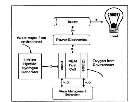
Battery
Water vapor from Power Electronics oad
environment ;71C
Lithium 0 PEM Q Oxygen from
Hydride 2-H2 Fuel Environment
Hydrogen < Cell
Generator
H2 H20
Water Management Subsystem
Figure 2: System concept for long-life, low-power PEM fuel cell system.
A concept for a hybrid low-power, long-life PEM fuel cell power system is shown in Figure 2. The PEM fuel cell uses oxygen from the environment and hydrogen produced by the
11 Chapter One: Introduction
lithium hydride to generate electricity. The concept is termed a hybrid system because the fuel cell charges a battery, which then powers the sensor. This prevents the load's varying power demand from affecting the fuel cell, which can lead to degradation [8].
The focus of this research is on the lithium hydride hydrogen generator. The generator takes water vapor from the ambient environment, reacts the water vapor with lithium hydride, and generates hydrogen, which the fuel cell uses to produce power. It may be possible to
activate the hydride using water produced at the fuel cell's cathode; however, this was not
pursued in this research.
In addition to the hydrogen generator, other subsystems are necessary to maximize the fuel cell life. A water management subsystem ensures that the cathode remains at 30-70% relative humidity and that the anode remains at 100% relative humidity. Power electronics prevent voltage oscillations caused by the load to reach the fuel cells because this can degrade
the fuel cell system [5].
1.3
PEM Fuel
Cells
Electrical LoadProton Exchange Membrane (PEM)
fuel cells are electrochemical devices that
convert the chemical energy in hydrogen Outlet Exhaust
Water and oxygen into electricity. The basic
workings of a PEM fuel cell are presented
in Figure 3 [9]. Hydrogen enters at the
anode where it reacts with a platinum S
catalyst. The hydrogen nucleus (a proton) Hydroen Oxygen
travels across a polymer membrane to the Inlet Inlet
cathode while its electron travels through
0
Anode]Cathode
an external circuit to generate electricity. Electrolyte
At the cathode, the proton, electron, and an Figure 3: Schematic of PEM fuel cell. Adapted
oxygen atom combine to form water. This from a diagram in [9].
means that PEM fuel cells can generate electricity while only exhausting water. The devices also
have very high energy conversion efficiencies. Theoretical efficiencies come close to 83% and
practical efficiencies are approximately 65% [10].
Although PEM fuel cells were invented in the 1960s, they are not widely used [11]. First, PEM fuel cells are expensive, mainly due to their need for a platinum catalyst to oxidize the hydrogen. Second, PEM fuel cells are subject to degradation. Thirdly, PEM fuel cells require storage of hydrogen, which is an engineering challenge.
1.4
Thesis Organization
The objective of this research is the development of a lithium hydride based hydrogen generator for low power, long life PEM fuel cell power systems. The potential of lithium hydride as a hydrogen source for low power, long life systems is evaluated.
Chapter 2 focuses on the selection of lithium hydride as a source of hydrogen. At the start of this research, lithium hydride was selected for three reasons: its high gravimetric hydrogen content, the simplicity with the reaction is controlled, and the assumption that the reaction reached 100% completion. The final assumption was incomplete, based on later experimental evidence.
Chapter 3 presents the design of a lithium hydride generator. Initially, active designs were attempted that pumped liquid water into the system or that relied on active valves. Finally, a passive design was pursued that relied on a compliant valve to regulate pressure.
Chapter 4 discusses the modeling work that was done on the generator's passive dynamics. The model was compared with experimental results.
Chapter 5 presents the benchtop prototype system that was used to study the passive generator in a fuel cell system. The experimental system was designed to run for 3 months and produce 250 mW average power. After 2 months, the fuel cells experienced hydrogen starvation and stopped producing power.
Chapter 6 focuses on research performed to explain why the prototype in Chapter 5 suffered hydrogen starvation. The experiments concentrated on the rate of hydrogen production over longer time periods (1-3 months) than previously considered and found that the rate significantly decreases.
Finally, Chapter 7 is not connected to the development of the hydrogen generator but presents work done during this thesis which investigates the problem of nitrogen building up in the anode while the fuel cell is operating in Dead Ended Anode (DEA) mode. A passive nitrogen release mechanism was developed.
Chapter One: Introduction 13
CHAPTER
2
LITHIUM
HYDRIDE
AS
A SOURCE OF HYDROGEN
Storage of hydrogen, the fuel of PEM fuel cells, is a difficult task [12]. This thesis
focuses on storing hydrogen in lithium hydride, which is a type of metal hydride. A metal
hydride is a compound of metal bonded with hydrogen. Lithium hydride releases hydrogen
through chemical reaction with water to produce hydrogen gas and other byproducts. It was
selected for this study because it has a high weight density of hydrogen, the production of
hydrogen is simple to control by varying its exposure to water, and because it was assumed that
lithium hydrogen is able to react almost completely.
2.1 Solid State Hydrogen Storage in Metal Hydrides
2.1.1
Hydrogen Economy
Hydrogen has long been advocated as a solution to the world's energy problems [13].
Hydrogen has the highest energy density of any substance in the universe with 286 kJ/mol.
Additionally, it is the most abundant element in the universe and composes over 75% of all
matter [14]. To convert hydrogen's chemical energy into electrical energy, it can be used in fuel
cell devices, which offer high efficiencies and are environmentally friendly because they only
exhaust water.
There are also many drawbacks. While hydrogen is the most abundant element in the
universe, it rarely exists by itself on earth and must be extracted from other compounds.
Approximately 95% of hydrogen used today comes from the steam reforming of natural gas,
which makes hydrogen as neither as clean nor as efficient as it would otherwise be [15].
Two of the most common methods of storing hydrogen are compressing it to hundreds of
megapascals or storing it as a liquid. Because of their complexity and high energy overhead,
Chapter Two: Lithium Hydride as a Source of Hydrogen
14
neither of these methods were thought practical for this study. This research focuses on a class of hydrogen storage materials known as metal hydrides.
2.1.2
Metal Hydrides
Metal hydrides are a wide range of compounds that feature hydrogen bonded to a metal. Each hydride has different chemical characteristics including hydrogen weight content and hydrogen release mechanism. Figure 4 contains a graph of various hydrides and their percent
weight of hydrogen [16].
2.1.3
Reversible vs. Nonreversible Hydrides
Metal hydrides are commonly classified based on how they release hydrogen. Reversible or pressure-release hydrides are hydrides that release hydrogen through changes in pressure. The second group is termed irreversible or chemical-release hydrides, which release hydrogen through chemical reaction. Pressure-release hydrides are classified as reversible because it normally requires much less energy to regenerate them than chemical-release hydrides. Many
will reabsorb hydrogen simply by exposing them to hydrogen gas at a high pressure. Chemical-release hydrides require greater amounts of energy and it is often considered impractical to recharge them. On the other hand, chemical release hydrides normally have higher hydrogen
40 35 -0 0C30 -&-25 -20 15 15 2 10
51I
0Selected Ionic Hydrides
Figure 4: Maximum hydrogen weight efficiencies of various ionic hydride [16].
content than reversible hydrides. These classes are not mutually exclusive; under certain circumstances, reversible hydrides may release hydrogen through irreversible processes [16].
Currently, much research is being devoted to complex hydrides because of their high hydrogen content and potential to be recycled. However, many of these require external catalysts and have other constraints. For example, sodium borohydride, NaBH4, promises high gravimetric content of hydrogen but requires a catalyst and must be mixed in a solution to prevent catalyst degradation [17].
2.2 Lithium Hydride
Of the various hydrides, lithium hydride (LiH) was chosen for study because it best met the
research objectives outlined in the introduction for long life, low power systems. Before
describing the suitability of lithium hydride for this project, the compound's chemistry is
discussed. Despite being studied for almost 50 years [18], its chemistry is still not fully understood and competing theories exist as to what controls the release of hydrogen.
2.2.1
Background of Lithium Hydride
Lithium hydride has long been considered a potential source of hydrogen in PEM fuel cells.
It served as the hydrogen source for the first PEM fuel cells developed by General Electric and the US Army in the 1960s [19], [11]. Since this original study, the compound has been often considered as a hydrogen storage mechanism for PEM fuel cells. Past research has investigated lithium hydride's potential for use in underwater vehicles [20] and for automobile transportation [21]. Lithium hydride is often bypassed as a source of hydrogen because of the high energy costs to regenerate [22]. The ability to regenerate the hydride is not important in this study because it is assumed that the sensor cannot be refueled once placed into operation.
In addition to energy storage, lithium hydride finds wide use as neutron shielding in nuclear
reactors [23]. Lithium hydride's radioactive isotope, lithium deuteride, is used for fusion in hydrogen bombs [24].
A large amount of research has been devoted to the compound's chemistry and a comprehensive literature review is found in [25]. The chemistry relevant to this research will be discussed next.
Chapter Two: Lithium Hydride as a Source of Hydrogen
16
0>" H20
enters
LiOH-H
20
Forms if Po > 520 Pa
Figure 5: Layering of products of LiH
hydrolysis reaction [25].
2.2.2
Hydrolysis of LiH
The reaction of interest to this study is the production of hydrogen from lithium hydride,
which occurs when the compound reacts with water. This reaction is exothermic and releases
90.7 kJ/mol of hydride [26]. The chemical equation for this reaction is:
LiH+H
20->LiOH+H
2(1)
Although (1) helps one understand the overall hydrogen-generating process, it is
oversimplified. The true reaction occurs in a series of steps with products depending on
temperature, hydrogen partial pressure, and water partial pressure (relative humidity) [27].
Lithium hydroxide (LiOH) or lithium hydroxide monohydrate (LiOH-H
20) are the favored
byproducts under pressures and humidities considered in this study [25]. If the hydrolysis
reaction is carried out in an air atmosphere containing carbon dioxide, lithium hydroxide will
react with carbon dioxide to produce lithium carbonate
(Li2CO3)[28].
The layers of byproducts that form on lithium hydride during hydrolysis are depicted in
Figure 5. The product lithium hydroxide forms a thickening layer through which water must
pass for the reaction to continue. Between the lithium hydride and hydroxide exists a thin layer
of lithium oxide. This layer is only a few hundred Angstroms thick but must exist because
17 Chapter Two: Lithium Hydride as a Source of Hydrogen
lithium hydride and lithium hydroxide cannot thermodynamically exist next to one another. This layer, which is believed to maintain constant thickness as the reaction proceeds, is important when considering the rate of reaction [29].
The formation of lithium hydroxide monohydrate (LiOH.H20) is important to this study. Lithium hydroxide monohydrate occurs when water molecules bond to the lithium hydroxide crystal and forms when lithium hydroxide is exposed to relative humidities greater than 15% and temperatures less than 500 C [30]. Lithium hydroxide monohydrate releases its water when heated to above 1000 C [31]. Because one mole of lithium hydroxide will absorb one mole of water, lithium hydroxide monohydrate formation has implications on generator design; specifically, more water is required than would be otherwise necessary.
Given the above product layers, a more complete description of the hydrolysis reaction is the following series of equations given in [32]:
2LiH + H20->Li2O+2H2 (2)
Li2O+H20->2LiOH (3)
Given proper humidity conditions, the following will occur
LiOH + H20 -> LiOH.H20 (4)
Depending on the presence of carbon dioxide, lithium carbonate will form:
2LiOH + CO2 -> Li2CO+ H20
(5)
These equations indicate that lithium hydride first produces hydrogen gas and lithium oxide. The lithium oxide then reacts with water to form lithium hydroxide (or lithium hydroxide monohydrate).
2.2.3
Rate of Hydrogen Production
-
Tri-layer Model
The controlling mechanism of the rate of hydrogen production has been well studied and debated in literature [25]. Early work found in [18] mentions that the rate of hydrogen production
Chapter Two: Lithium Hydride as a Source of Hydrogen
18
is not controlled by diffusion of water vapor through the product layer of lithium hydroxide while work presented in [33] claims that diffusion has a substantial effect. The most recent
theory supported by [34], [30], and [29] is the "trilayer model." A diagram of this model is
shown in Figure 5. Instead of lithium hydride and lithium hydroxide existing next to one another (which is unstable chemically), a thin layer of lithium oxide (less than 100 Angstroms) forms between the lithium hydride and the lithium hydroxide. According to this model, micro-cracks develop in the lithium hydroxide layer as it forms. The micro-cracks are due to differences in the lattice structure between lithium hydride and lithium hydroxide. They allow water vapor to penetrate through to the unreacted hydride bed. Throughout the hydrolysis process, the layer of lithium oxide maintains constant thickness and it is the layer of lithium oxide, not lithium hydroxide, which is the rate-controlling mechanism [29].
This theory has important implications for this study because it means that the hydrolysis reaction should not "clog up" over time; water vapor should be able to reach the hydride through micro-cracks and hydrolysis should continue. This characteristic, if true over long periods of time, makes lithium hydride ideal for long-life, low power PEM fuel cell systems.
2.3
Suitability of LiH for PEM Fuel Cell Systems
Of the many forms of hydrogen storage, lithium hydride was selected for study for long-life, low-power systems because of three characteristics: its high hydrogen content, the simplicity with which the reaction is controlled, and the hypothesis that the reaction does not clog up over
long periods of time.
2.3.1
High Gravimetric Weight Content of Hydrogen
The first reason lithium hydride was selected for study is its high gravimetric weight content of hydrogen. Table 1 shows lithium hydride compared with a variety of actively researched hydrides. Certain borohydrides have higher weight densities, but many, such as sodium borohydride, (NaBH4) require complex catalysts, which are prone to degradation [17].
Beryllium borohydride has a very high hydrogen content but is too reactive and toxic to be considered [35]. Alkali metal hydrides, such as calcium hydride, sodium hydride, and lithium hydride are all simpler in the sense that they only require water to produce hydrogen. Of these hydrides, lithium hydride has the highest hydrogen weight content.
That lithium hydride only requires water to produce hydrogen gives it an even higher weight efficiency. For the low powers considered in this thesis, water is available either from the
environment (as water vapor) or from the fuel cell's exhaust. This means that water does not
need to be carried with the system. For every gram of LiH in a power supply, 0.25 grams of
hydrogen can theoretically be produced. This yields a weight efficiency of 25%.
Hydride Gravimetric Hydrogen
Weight Content LiBH4 18.4% NaBH4 10.6% Be(BH2)4 20.8% NaAlH4 7.4% NaH 4.1% CaH2 4.7% LiH 12.5%
Table 1: Table of various hydrides and their gravimetric hydrogen content, defined as the mass
of the hydrogen divided by the total mass of the hydride. Derived from information in [36].
2.3.2
Controlling Lithium Hydride Hydrolysis
The second reason for choosing lithium hydride is that the reaction is simple; hydrogen production only requires application of liquid water or water vapor. This indicates that in order to control the reaction, it is necessary to control the amount of water reaching the hydride.
A series of experiments conducted in this study show the hydrolysis reaction's dependence on the relative humidity of the atmosphere surrounding the hydride. The dependence of the rate of hydrogen production on exposed lithium hydride surface area is also investigated. These experiments use the setup depicted in Figure 6. For these experiments, three holes of diameter
0.83 cm (for a total surface area of 1.6 cm2) and depth 1 cm are drilled into a plastic block and
filled with approximately 0.5 g of lithium hydride each. The block is placed in a sealed
container, which is held at a constant relative humidity through the use of a saturated salt solutions. Water vapor produced by the saturated salt solution reacts with the lithium hydride; the produced hydrogen is collected in an 1 L inverted graduated cylinder. Five experiments were
run, each at a different relative humidity. The humidities tested are listed in Table 2. Each experiment lasts approximately 10 hours, during which the rate of hydrogen production reaches a rate that is very nearly constant, as reported in literature [29]. The rate of H2 production is recorded in this constant region.
Inverted 1 L cylinder to measure volume of hydrogen produced
10.4 cm
Block containing varying number of LiH pockets
Figure 6: Experimental setup used to demonstrate effect of relative humidity on
hydrogen production rate.
Relative Humidity
Salt used to Control Humidity
11%
Lithium Chloride
33%
Magnesium Chloride
53%
Magnesium Nitrate
74%
Sodium Chloride
100%
Water (No Salt Added)
Table 2: Relative humidities to test rate of hydrogen production and salts producing these
humidities. These numbers assume the temperature is 200 C [37].
The results of these experiments are compiled in Figure 7. The rate of hydrogen production
increases approximately linearly with relative humidity.
A second series of experiments was run that investigated the effect of varying exposed
lithium hydride surface area on the rate of hydrogen production. These experiments also used
the experimental setup depicted in Figure 6, although with constant humidity set at 34%. Six
holes were drilled in a plastic block (also of 0.83 cm diameter and 1 cm depth). To vary the surface area of lithium hydride, the number of holes filled with hydride was varied from 1 to 6. In each experiment, the relative humidity was held constant by using a solution saturated with magnesium chloride. The results of these experiments are presented in Figure 8. The rate of hydrogen production is roughly linear with increasing surface area.
A
06
S0 10 20 30 40 50 60 70 0 0 10
Relative Humidity (%)
Figure 7: Rate of hydrogen production as a function of relative
humidity.
2
a
Area of Exposed Hydride
Figure 8: Rate of hydrogen production as a function of surface area.
2.3.3
Total Hydrogen Yield of Lithium Hydride
The third reason lithium hydride was selected for long life, low power fuel cell power systems was its perceived high utilization efficiency. In this thesis, the utilization efficiency is defined as the moles of hydrogen produced over the course of an experiment divided by the
theoretical number of moles contained in a given quantity of lithium hydride. A utilization efficiency of 1 indicates that the hydride has produced its theoretical amount of hydrogen; a utilization efficiency of less than 1 indicates that something has prevented the release of hydrogen. A hydrogen storage source should have a high hydrogen utilization efficiency to avoid wasted system mass and wasted system volume.
According to experiments run in literature, lithium hydride has a high utilization efficiency of above 90% [26]. This research tests the utilization efficiency using an experimental setup similar to that shown in Figure 6. Two experiments were run, labeled A and B in this thesis. In each experiment a flask was filled with a measured quantity of lithium hydride. The initial volumes and masses of the lithium hydride in both of these experiments is presented in Table 3.
A source of water vapor at 100% humidity was placed in the sealed container alongside the
hydride. Over the next week, the water vapor reacted with the lithium hydride and the volume of hydrogen gas produced was measured. The final volume of hydrogen gas produced is also presented in Table 3. The final volume is the total volume of hydrogen output before the lithium
hydride stopped producing hydrogen. Figure 9 shows the reaction's percent completion over
time, where 100% corresponds to the theoretical output of hydrogen. The experimental results are close to those presented in [26], which carries out a similar experiment on lithium hydride
and determines that lithium hydride has a utilization efficiency of 91%. The results found in [26]
are shown in Figure 10.
Experiment Initial Volume Exposed Theoretical Actual H2 Utilization
Mass of of LiH Surface H2 Yield Yield Efficiency
LiH Area (Liters) (Liters) (%)
A 0.8 g 2.79 cm 3.98 cm2 2.42 2.40 99
B 1.4 g 3.78 cm 3.98 cm2 4.23 3.97 94
Table 3: Initial parameters to test whether lithium hydride releases the theoretical amount of hydrogen. The experimental results and percent utilization are contained in the final two columns.
Chapter Two: Lithium Hydride as a Source of Hydrogen
23
0 a) C 0 0 C a) 1~ a)
a-100 - 90- 80- 70- 60- 50- 40- 30-20 10 0-$Completion of Reaction for Experiment B
0 1 2 3 4 5 6 7 8
Time (Days)
Figure 9: Percent completion of reaction for Experiment B.
0 100 200 300
Time (min)
400 600
Figure 10: Percent conversion for lithium hydride experiment performed in [26].
Points are experimental data points; the curve is the prediction of a model.
The results of these short term experiments indicate that lithium hydride should be
well-suited for high efficiency PEM fuel cell power systems because of its high hydrogen yield. The
experiments indicate that over time periods measured in days and for small quantities of lithium
hydride (around 1 gram), lithium hydride is able to produce very close to its theoretical content
Chapter Two: Lithium Hydride as a Source of Hydrogen
24
C 0 0 0 Cn 100 90 80 70 60 s0 40 30 20 10 0
of hydrogen. This agrees with the tri-layer model which states that a thickening lithium
hydroxide layer does not control lithium hydride's ability to produce hydrogen.
The experimental results of this section, 2.3.3, are presented to explain why lithium hydride was chosen for long-life fuel cell systems, although this research (presented in Chapter 5 and 6 of this thesis) shows that the results presented here are incomplete. Experiments discussed in later chapters that are carried out over longer time periods (1-3 months) indicate that the rate of hydrogen production does decrease significantly and that, over significantly long time periods, lithium hydroxide prevents water from reaching the hydride. For this reason, the high hydrogen yield of lithium hydride is the weakest of the three reasons for choosing lithium hydride for use in long life PEM fuel cell power systems.
2.4
Conclusions
Effective hydrogen storage is a difficult problem and a challenge for widespread adoption of hydrogen. Of the many possible solutions, lithium hydride was chosen for this research, which centers on long-life, low-power PEM fuel cell systems. Lithium hydride was chosen because it
has a high gravimetric weight efficiency of hydrogen, controlling the reaction is simple, and its
actual hydrogen output was very close to its theoretical hydrogen output. As research progressed, it became clear that the third assumption was not entirely correct.
Once lithium hydride was selected as the hydrogen storage medium, it was necessary to design a hydrogen generator, which is discussed in the next chapter.
Chapter Two: Lithium Hydride as a Source of Hydrogen
25
CHAPTER
3
DESIGN OF
A
HYDROGEN GENERATOR BASED ON
LITHIUM
HYDRIDE
The system concept of lithium hydride providing fuel for a hybrid PEM fuel cell system,
it was necessary to design a hydrogen generator. This design is carried out with a number of objectives and assumptions.
Assumptions of Hydrogen Generator
1. The system would be operated in terrestrial environments.
2. Environmental temperatures would range from 10-40" C.
3. It was assumed the system would not be used in a very dry environment, i.e. the
environmental relative humidity would be greater than 20%. 4. The system would remain stationary and upright.
Objectives of Hydrogen Generator Design
1. Produce hydrogen at a controlled pressure for use in low power PEM fuel cells.
2. Have the ability to produce hydrogen for months or years or at least be scalable to these lifetimes.
3. High hydrogen volume and weight efficiency so that the generator has the potential to
be built into a small and lightweight package.
4. Very little to no electrical power consumption because the system is designed for low-power applications.
5. A simple design - a complex design has more components that can fail over a
long-lifetime.
The following sections describe the design process that went into each generator iteration as well as experimental results.
Actively Controlled Designs
The first iteration of hydrogen generators relies on active control. These generators illustrate that it is possible to control the generator's pressure through actuating with liquid water or water vapor.
3.1.1
Peristaltic Pump and Liquid Water Actuation
The first generator design relies on pumping water droplets to activate the hydride; the rate of droplets released into the system is used to control the hydrogen pressure.
One design challenge is to decide how to deliver water into the system. This is because the system requires such low flow rates of water in order to produce the necessary hydrogen. A 250 mW PEM fuel cell system requires 1.46x10~4 moles per second of hydrogen (assuming 65%
efficiency). Given that the hydrolysis of lithium hydride requires one mole of water for every mole of hydrogen produced, this means that the hydrogen generator would require a water input of 2.62x10⁻⁵ grams of water per second which equals 2.62x10⁻⁵ milliliters per second of water, which is a very small amount of water for normal pumps to deliver.
A number of micro-pumps were considered. Microfluidic dispensers were first considered [38]; however, they were not chosen due to cost and difficulty integrating into a mobile system.
Commercially available micro-piezo print heads such as those found on a desktop printer [39] were investigated but it was concluded that they would be too complex to control. Micro-piezo pumps were considered but decided against due to the need for an external voltage amplifier [40]. Finally, a small peristaltic pump was chosen. It was selected because of its low-cost, ease of use, and ability to drop small amounts of water (approximately 1 milliliter per second) into the generator.
Chapter Three: Design of a Hydrogen Generator Using Lithium Hydride
3.1
The peristaltic pump still delivers much higher flow rates of water than required, but it is recognized that it does not need to provide micro-liter flow rates. Instead, the pump releases a droplet of water into the system onto a wick without contacting the hydride. The droplet evaporates and reacts with the hydride over a 30-40 minute time period until another droplet is
needed. Using this approach also avoids liquid water touching lithium hydride, which is a
violent reaction and can ignite.
The remainder of this initial system is designed as pictured in Figure 11. Lithium hydride is
placed into five 10 mL glass beakers, each filled with approximately 0.5 g of hydride. To
provide a closed system, the beakers are packed in a sealed chamber (an OtterboxTM was used). The chamber is not perfectly sealed to hydrogen and allows a small amount of gas leakage. This is beneficial to test the controller because it allows the generator's pressure to decrease over time. This mimics the effect of a fuel cell, which would consume the hydrogen.
The control scheme was simple: when the pressure dropped below a pre-determined value, the pump would release a droplet of approximately 50 microliters onto the wick. The droplet
would evaporate and react with the hydride.
Water Source Sealed
(500 mL Cylinder) Container
Controller Pressure
Snsor
Wick
Pump Flasks of LiH
Figure 11: Experimental setup used to actively control hydrogen pressure.
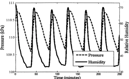
The objective of this experiment was to determine whether the pressure of the lithium hydride could be controlled at a pre-determined operating point within an error bounds. For the purpose of this experiment, the operating point was set to 110 kPa with error bounds of ±1 kPa. The results of the experiment are presented in Figure 12 and Figure 13.
Figure 12 presents the graph of pressure over time. Each vertical line represents a point at which the pump delivered a droplet into the system. From the plot, it is evident that the system was able to control the pressure at the set point of 110 kPa and within the error bounds. The pressure signal exhibited periodic oscillations, with one droplet of water released every 40 minutes.
Figure 13 plots the system pressure and humidity on the same graph. The pressure and humidity rise at regular intervals; a droplet is introduced into the system, the droplet evaporates, and the water vapor subsequently reacts with the lithium hydride. The peaks of the humidity always occur before the peaks in pressure. This trend is reported in literature and relates to the difference between the time when the water vapor is absorbed by the hydride bed and when it reacts with the lithium hydride [18].
U) CL Droplet Released (1 sec) Error Target Pressure 0 .... 100...200 0 so 10 Ls% 20 Time [minutes]
Figure 12: Graph of pressure versus time which demonstrates control of system pressure at 1.1 bar.
111 110.5 W % - " 110-109.5 -]--Pressure 40 r --- Humidity 10905 112o2 0 A 150 Time (minutes)
Figure 13: Plot of system humidity and p re during controlled
experiment.
3.1.2
Water Vapor Actuation
The next set of generator experiments focus on actuating using only water vapor. This is
done to make the system more efficient and versatile. To activate the hydride, the peristaltic
pump design requires a source of liquid water. This means that liquid water must either be
carried with the power system or obtained from the environment. Storing liquid water in the fuel
cell system increases system weight and reduces weight efficiency. Obtaining water from the
environment (assuming water is not readily available in the sensor's surroundings) means
condensing water vapor, which is energetically expensive. Using only water vapor to activate
the hydride avoids these difficulties. Water vapor is available in significant amounts almost
anywhere on earth.
3.1.2.A Servo Actuator in Combination with Nafion Membrane Part 1
The second design still implements three key new design elements: actuation relying only
on water vapor, the use of a valve mechanism, and includes Nafion as a water transport medium.
Relying only on water vapor to activate the hydride raised the question of how to input
water vapor into the system. Initially, pumping water vapor with the same peristaltic pump from
the previous design was attempted but too was energetically expensive to be feasible. Instead, it
was concluded that a valve mechanism would be most efficient. When the generator pressure
dropped below a certain value, the valve would open to allow water vapor to enter the generator from the environment, otherwise, the generator would be closed.
To build a valve, it was necessary to have a membrane that allowed for water vapor to enter the system but prevented hydrogen from escaping. This behavior is exhibited by a material already present in PEM fuel cells: Nafion. Nafion is a polymer that was developed by DuPont in the 1960s and comes as a clear, thin plastic-like sheet. It is rugged and has a chemical structure similar to Teflon [41]. In PEM fuel cells, Nafion serves as the proton transport membrane which transports protons from the anode to the cathode. A mathematical description
of Nafion's transport properties are given in Chapter 4, but what is important for the
development of a hydrogen generator is the fact that it allows water to pass much more easily than it does hydrogen or other system gases such as nitrogen. Therefore Nafion can be used as a
gateway, which allows water to enter but maintains the generator's internal hydrogen pressure. This is depicted in Figure 14.
Figure 14: Mass transport in Nafion membrane.
Nafion will transport water from regions
of higher water partial pressure to regions of
lower water partial pressure. This means that
Nafion can transport water from regions of lower
total pressure to regions of higher total pressure,
as long as there is a decrease in water partial
pressure. This feature is depicted for two sealed
chambers in Figure 15.
This characteristic is
good for the design of a hydrogen generator
because it means that Nafion can deliver water
Nafion
PtOt,
1
H20 11H201Ptoi,2
PH20,1 H20
PH
20,2
Ptot, <
tot,2
PH
20,1>
PH20,2Figure 15: Ability of Nafion to transport water to regions of higher total pressure
vapor from the environment into areas of higher hydrogen pressure. The type of Nafion use for the designs presented in this thesis is Nafion 117.
Pressure Top View - Open
sensor
---Lithium Rubber Servo
Seaed Hydride Stopper Motor
chamber
Nafion ' H2vapor enters from
Membrane environment
Top View - Closed
Lithium Servo
Hydride Rubber Motor
Bed Stoppr
Naflon Rubber stopper prevents H20 vapor
Membrane from entering generator
Figure 16: Diagram of mechanism that would control pressure
by opening and closing a valve.
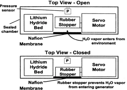
The first design that utilized Nafion to transport water vapor into the system is pictured in Figure 16. A rubber stopper was attached to a servomotor that acted as a valve to water vapor. If the pressure inside the generator was too high, the servo would press the rubber stopped against the Nafion, which was intended to prevent water vapor from entering the system. If the pressure were too low, the servo would open the valve and allow water vapor to enter the system
and react with the bed of lithium hydride.
The valve's ability to control humidity within the generator was tested. The results of
this test are presented in Figure 17. The plot shows the relative humidity inside the generator with the valve open versus the humidity with it closed. The results indicate that Nafion allowed water to enter the system. Unfortunately, whether the plug was open or closed, the humidity within the device rose considerably. This indicated that the valve was unable to prevent water vapor from entering the device and, therefore, would be unable to control the hydride reaction.
A better seal was necessary and this was the focus of the next design.
Internal Humidity Test for HydraCell
0 10 20 30 40 50 60
Time (minutes)
Figure 17: Graph of humidity versus time for valve open and valve closed.
3.1.2.B Servo Actuator in Combination with Nafion Membrane Part 2
Open Configuration
Closed Configuration
L
---.---Figure 18: Third iteration of active hydrogen
generator.
Figure 19: External view of third
iteration.
The next iteration of the vapor-actuated hydride system had the goal of producing a valve
that could effectively block humidity from entering the system when closed.
This was
accomplished through use of a precisely-machined Plexiglas door, which would open upon
commands to a servomotor. The servo's rotational motion was translated into linear motion
through the use of a rack and pinion gear. The system design is presented in Figure 18. An
image of the generator is in Figure 19. The image shows the generator's Nafion membrane,
glued to the outside of the generator. In the image, the Plexiglas door is halfway open.
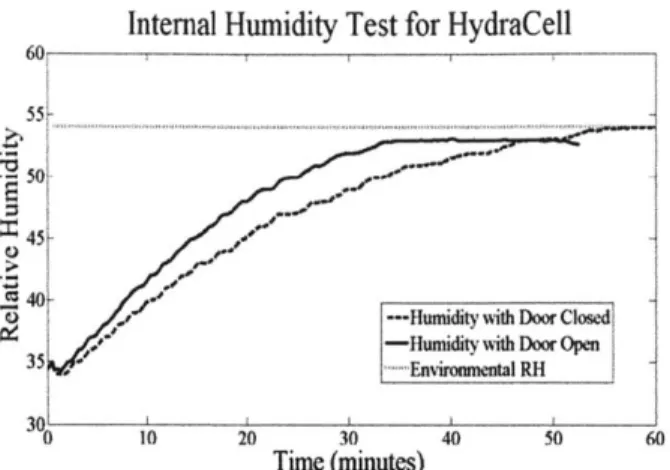
This iteration was tested for its ability to control relative humidity and pressure. The results of these tests are shown in Figure 20 and Figure 21. Due to the precisely machined assembly holding the Plexiglas door in place, this system exhibited much better performance than previous iterations. As shown in Figure 20, there was a significant difference between the rate of rise of system humidity with the door closed as with it open. After establishing humidity control, the generator was filled with approximately 2 grams of hydride and tested for its ability to control pressure. Figure 21 presents a plot of the controlled system pressure versus time. The operating point was arbitrarily set at 105 kPa, which the generator is able to maintain after rising from atmospheric pressure. This experiment was run using only atmospheric humidity (approximately
30%) to generate hydrogen. The blip on the pressure graph near the 10 minute mark represents
a droplet of water that was dropped on the Nafion surface. If the droplet of water were a disturbance, the generator was able to successfully reject it; the pressure did not become unstable and returned to 105 kPa within 10 minutes. Finally, this system design accomplished the goal of reducing the pressure oscillations seen with the first design discussed. After the initial rise and disturbance, the pressure oscillates much less than the system using a peristaltic pump.
55-40
35 -Humidity with Door Closed
---Humidity with Door Open
0 10 20 30 40 50 60 70 80 90
Time (minutes)
Figure 20: Comparing humidity rise inside third iteration with door
closed and with door open.
105.
104.51
-0 10 20 30 40 50 60 70 80 90 100
Time (minutes)
Figure 21: Pressure response of third iteration. Pressure controlled
at 105 kPa.
![Figure 4: Maximum hydrogen weight efficiencies of various ionic hydride [16].](https://thumb-eu.123doks.com/thumbv2/123doknet/14732527.573342/15.918.171.701.692.1001/figure-maximum-hydrogen-weight-efficiencies-various-ionic-hydride.webp)