DEPARTMENT OF
AERONAUTICS
AND
ASTRONAUTICS
MIT AERONAUTICAL SYSTEMS LABORATORY
DEVELOPMENT AND EVALUATION OF AN ELECTRONIC VERTICAL SITUATION DISPLAY
Sanjay S. Vakil, Alan H. Midkiff, R. John Hansman Aeronautical Systems Laboratory
Department of Aeronautics & Astronautics Massachusetts Institute of Technology
Cambridge, Massachusetts USA June 1996
Chapter 1
Introduction
Current advanced commercial transport aircraft, such as the Boeing B777/B747-400, the Airbus A320/A340 and the McDonnell Douglas MD-11, rely on AutoFlight Systems (AFS) for flight management, navigation and inner loop control. These systems have evolved from straightforward autopilots into multiple computers capable of sophisticated and interrelated tasks. These tasks span the range from high level flight management to low level inner loop control. In addition, these systems provide envelope protection to prevent pilots from committing mistakes such as stalling the aircraft or lowering flaps at high speeds.
Unfortunately, as these systems have become more complex and interconnected, a new class of problems has developed associated with pilots’ interaction with the automation. Many incidents have been reported where there exists some confusion between the pilots’ expectations of the AFS and what the system is actually doing (Corwin, 1995). This confusion has been termed a Mode Awareness Problem (MAP).
After a description of the AFS, a formal definition of mode awareness problems is presented in Section 1.3 followed by representative incidents in which mode awareness problems are suspected as being a contributory factor.
1.1
AutoFlight System Description
The AFS in modern aircraft has three distinct mechanisms which correspond loosely to the time constants associated with the differing types of control. At the lowest level are a set of inner loop controllers, especially in Fly By Wire (FBW) systems, which improve the handling
characteristics of the aircraft by modifying the dynamics to which the pilot is exposed and provide aircraft attitude control. Above these are a set of autopilots (A/P) which command the aircraft to a specific state by providing inputs to the lower level controllers, much as a pilot would do manually. Finally, the Flight Management Computer (FMC) is a high level planning tool which can be programmed by the pilot to fly a complex predefined trajectory. These levels are discussed in more detail below.
1.1.1 Fly By Wire and Inner Loop Controllers
Inner loop controllers fly the aircraft to a target flight attitude. For example, if an external disturbance caused an aircraft to roll, the controller would return the aircraft to a level state, but would not correct for the integrated effects of the roll, such as a change in heading, or a loss of altitude. In a similar manner, the controller which maintains the aircraft pitch would compensate for a disturbance causing the pitch to change, but would not return the aircraft to the commanded altitude.
In addition, these controllers also perform a secondary role in Fly By Wire (FBW) aircraft, such as the Airbus A320/A340. Even the most basic flight control devices, such as the yoke (or side stick), pedals and throttle do not provide raw inputs directly to the control surfaces in FBW aircraft. Instead, the inputs are filtered and modified in a manner designed to provide a consistent set of dynamics to the pilot. This is intended to improve the safety of the aircraft by providing consistent responses to pilot inputs (Fishbein, 1995).
Even in aircraft which are not FBW, a set of low level inner loop systems may exist to control certain aircraft modes. The most well known of these is the yaw damper that is used on
the standard control mechanisms to allow more flexibility in flight. For example, Control Wheel Steering (CWS) is available in the MD-11 and allows the pilot to directly control the roll angle of the aircraft.
1.1.2 Simple Autopilots
Simple autopilots control the aircraft at a level higher than the low level controllers by allowing the pilot to command the aircraft into a specific target state, such as holding at a commanded altitude, heading, or speed, or descending at a commanded rate. The autopilot system controls the aircraft around the commanded input of the pilot by providing inputs to the low level controllers to fly the aircraft to the designated path and speed (Fishbein, 1995).
In most cases, the A/P is also minimally capable of switching targets, and switching which specific A/P is currently controlling the aircraft. This capability allows the automation to make simple transitions to fly individual legs of segmented trajectory. For example, a system designed to control around a vertical speed may also include the logic necessary to stop the descent at a commanded altitude. When the aircraft levels out, a different A/P mechanism would control the aircraft to maintain that altitude.
The input to the autopilot is usually a Mode Control Panel (MCP), also referred to as a Flight Control Unit (FCU), which provides mechanisms to dial in various aircraft targets (altitude, vertical speed, airspeed, heading, etc.). The pilot then explicitly engages the A/P to capture the target. Limiting the complexity and capability of the autopilot system is the fact that only one target is associated with an individual autopilot system.
1.1.3 Flight Management System
The FMS is the strategic interface to the aircraft which drives the set of low level autopilots. The FMS has onboard an extensive database of navigation aids, waypoints, and standard arrival and departure procedures. Pilots use the FMS with a flight plan route to drive the set of low level autopilots. Pilots program the flight plan, consisting of waypoints and constraints into the FMS by interacting through a keypad-based Control and Display Unit (CDU). Using the flight plan, inputs from multiple navigation receivers and the database, the FMS provides inputs to the low level autopilots to flight the route automatically (Curran, 1992). The FMS can determine the most economical climb profiles, cruise altitudes, speeds and descent points to meet economic and wind constraints.
At a conceptual level, the FMS functions by switching between different vertical and lateral autopilot modes during different phases of flight without any need for further intervention from the pilot. This is particularly useful in long, uneventful stages of flight, such as cruise, though the FMS in modern aircraft is capable of fully automatic flights, including autonomous landings.
1.2
AutoFlight System Architectural Overview
Intrinsically, the higher level AutoFlight System function consists of switching between
different modes of aircraft automation with simple modes being strung together to create more
complicated flight trajectories. The following sections begin with an overview of mode definitions and the various types of mode transitions. Next, differences between horizontal and vertical modes are examined in the context of currently available mode feedback
1.2.1 Mode Definition
In this context, a mode is defined as a state of the aircraft automation which has a particular set of target criteria, control characteristics and transition criteria. Target criteria are the values that are programmed by the pilot or by the automation to which the mode will control the aircraft. An example would be the target heading or altitude at which the aircraft is flown.
The control characteristics define the actuators and associated control laws that the automation will use to fly to the target criteria. An example is using the ailerons to control the roll angle of the aircraft to acquire and maintain a commanded heading.
Transition criteria define the situations in which the automation will switch from the active mode to a new mode. These criteria can be utilized to create complex flight trajectories. An example of a transition criterium is the commanded altitude when the aircraft is in a descending mode. When the aircraft reaches the commanded altitude the automation will switch the active mode from the one used for the descent to a mode that transitions smoothly to and maintains the commanded altitude. Another example is if the aircraft exceeded safety limits, the automation will switch the active mode to one which reduced the risk of exceeding those limits.
1.2.2 Types of Modes
Current AutoFlight Systems switch between two basic types of operating modes which have been termed base modes and macro modes.
Base Modes
Base modes are used in quasi-steady-state conditions and have an invariant set of targets. A base mode example would be a Vertical Speed mode where the aircraft attempts to maintain a specific vertical speed target by controlling pitch using the elevators and an airspeed by controlling the thrust.
Macro Modes
Macro modes consist of a linked sequence of base modes. Each base mode in the macro mode sequence has its own set of targets, implying a set of targets which vary over the course of the macro mode. Transitions between the base modes are made based on the mode transition criteria, such as altitude or indicated air speed. An example of a macro mode is the Autoland sequence, which transitions (in the vertical channel) between Altitude Hold, Glide Slope Capture, Flare, and Rollout with a different set of targets in each base mode.
1.2.3 Mode Transitions
There are three types of transitions between modes. A commanded transition is active as
soon as the selection is made. An example is pressing the Vertical Speed button, and thereby
activating the Vertical Speed mode. An uncommanded transition is one that is not directly
activated by the pilot. These transitions are usually some type of envelope protection. An
example is a transition caused by overspeed protection. Finally, automatic/conditional
transitions occur when, after arming, a mode engagement occurs at a transition criterium. An
example is the use of Glide Slope Capture to transition to a descent mode after the aircraft intersects with the ILS glide slope signal.
1.2.4 Horizontal and Vertical Modes
The AFS in a modern aircraft typically separates the guidance into uncoupled horizontal and vertical components. A simple example of a horizontal guidance base mode is using the MCP to command the aircraft to acquire and maintain a selected heading or track. A more complicated macro mode would be to use the CDU to program the FMS to fly a segmented trajectory in
Typical vertical guidance modes include using the MCP to fly level in an Altitude Hold mode, or maintaining a selected vertical speed with Vertical Speed mode. In each of these modes the aircraft is controlled to a vertical path and the commanded airspeed. The FMS is also capable of flying complex Vertical Navigation (VNAV) trajectories, programmed by the pilot through the CDU, however, this mode is limited in use as LNAV mode must also be engaged. This is required because VNAV mode consists of adding altitude and speed restrictions to the horizontal waypoints. These restrictions would not have any context without the horizontal references.
1.2.5 Mode Feedback
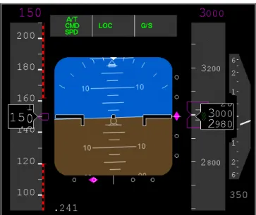
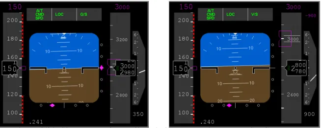
The Flight Mode Annunciator on the Primary Flight Display (PFD) of modern aircraft is normally the primary location of mode status information. FMAs typically display the current mode configuration of the aircraft in a text format. The mode configuration consists of both the active mode and any additional modes that may have been armed, such as glide slope or localizer capture modes.
Both a PFD and a FMA from the Boeing B747-400 are shown below in Figure 1.1. As can be seen, the FMA is located in the middle of the display directly above the artificial horizon. The FMA symbology shows that the aircraft’s Auto Throttle (A/T) mechanism is engaged and is being controlled by the autopilot (CMD) to follow a speed (SPD). In addition, the aircraft is in Lateral Navigation mode (LNAV) and currently holding altitude (ALT HLD) at 5000 ft.
1.2.6 AFS Input-Output Relationships
Two basic types of AFS input-output relationships can exist. The simpler is a quasi-steady-state model where each output quasi-steady-state is controlled by a single input: Single Input-Single Output (SISO). A typical Vertical Speed mode engages two independent SISO controllers: the aircraft’s pitch controls the vertical speed and the thrust controls the air speed. SISO models appear to be functionally adequate for most base modes.
The second type of relationship is one utilizing a Multiple Input-Multiple Output (MIMO) controller, where each output variable is controlled by more than one input. Some mode transitions appear to utilize a MIMO relationship. These transitions are typically of short duration and they do not appear to be modelled in detail by flight crews. An example of a complex mode transition is the 0.05g capture used in an Altitude Capture transition of the MD-11: when the aircraft is approaching a selected flight altitude, the intercept maneuver limits the normal acceleration to 0.05g.
1.3
Mode Awareness Problems
A mode awareness problem exists when there is confusion between the pilots’ expectations of the AFS and what the system is actually doing. Previous research (Sarter and Woods, 1992) has categorized mode awareness problems based on their underlying themes, such as problems related to VNAV modes, data entry, uncommanded mode transitions, infrequently used modes and features of the AFS etc.
In this work, mode awareness problems will be categorized in a less specific manner into three classically defined error categories: commission, omission and incorrect action (Sheridan, 1992). These are errors as viewed from the standpoint of the pilot: when the pilot believes that the AFS has committed an error. This allows a broader categorization, independent of the specific AFS mechanisms in question and instead focussing on the generic cause of mode confusion. In this research, mode awareness problems are said to have occurred when the aircraft AutoFlight System
1. executes an unexpected action - commission 2. fails to execute an expected action - omission
3. executes an action in an unexpected way - incorrect action
The next section will provide descriptions of three incidents which are examples of the types of mode awareness problems in this categorization.
1.3.1 Incidents Suspected to have Involved Mode Awareness Problems
A few specific incidents are described below in order to give examples of actual cases of mode awareness problems. The first example is an error of commission: an A300 at Nagoya was inadvertently put into a go-around mode (Mecham, 1994) resulting in the crew fighting the
unexpected result. The second example illustrates an error of omission when an A320 in Bangalore was set in an incorrect mode (Lenorovitz, 1990) during approach that caused it to fail to add power to maintain a sufficient airspeed. The final example is one of an incorrect action. Vertical path control confusion on an Airbus A320 at Strausbourg (Sparaco, 1994) caused a Controlled Flight into Terrain as the crew was unable to detect an incorrect mode selection.
Commission: Pitch Control in Go Around
On April 26, 1994, an Airbus A300 landing at Nagoya Airport was inadvertently put into Go Around (G/A) mode by the pilots. G/A mode is used in situations where a landing needs to be aborted, and the aircraft needs to be reconfigured to leave the runway airspace and gain altitude quickly in order to attempt another landing. The mode attempts to pitch the aircraft into a nose up attitude and add power in order to climb.
The inadvertent engaging of G/A mode led to the crew using the aircraft flight controls to fight the automation in an attempt to keep the aircraft in a descent for landing. The aircraft’s horizontal stabilizer was being trimmed for a nose up attitude as the automation attempted to overcome the pilots’ using the elevators to place the aircraft into a descent configuration. When the pilots finally decided to abort the landing and to perform a G/A maneuver, they reconfigured the elevators for a climb configuration, which, when combined with the trim state of the horizontal stabilizer, caused the aircraft to pitch up sharply, stall at low altitude and crash (Mecham, 1994).
Omission: Incorrect Mode Selection
In February of 1990, an A320 crashed in Bagalore. The incident is suspected to have been caused by the crew incorrectly setting the descent mode during the approach. The A320 has an
mode, the autothrust system limits the throttle to idle power, the mode does not allow the aircraft to necessarily maintain a commanded speed. In most high altitude descents, the pitch of the aircraft is used to maintain the commanded airspeed.
On this flight, an inexperienced first officer was flying the landing with the captain observing performance. According to the accident investigation, the crew entered the final approach phase of flight in a Vertical Speed mode (a “speed protected mode” which maintains the commanded speed) but then switched to the “idle open descent” mode (which does not maintain the commanded speed). The crew commented on the mode of the aircraft, and discussed how to disengage it, but did not actually do so. Neither crew member appeared to be monitoring the speed of the aircraft as it slowed to 25 kts below the 132 kts approach speed. It is speculated that the crew expected the AFS to automatically add power to the aircraft as it would do in a speed protected mode, such as the Vertical Speed mode normally used during approach.
This particular incident could be viewed as an error of omission. The crew expected that the aircraft was controlling the airspeed and relied on throttles to add power. The active mode of the aircraft did not allow this to occur.
Incorrect Action: Vertical Path Confusion
On January 20, 1992, an A320 aircraft crashed during a non-precision approach into Strausbourg airport. The aircraft was estimated to be descending at 3300 fpm, a much steeper rate than the approach was designed for. The approach to the airport specifies a gradual step-down with numerous level-off altitudes and short descent legs. Many pilots who land at Strausbourg realized that this complex approach trajectory could be safely approximated with a
flight path angle of 3.3°. This descent rate came sufficiently close to matching the multiple
It is speculated that the flight crew’s intent was to descend on this simplified path, but instead placed the aircraft into the wrong descent mode: Vertical Speed instead of Flight Path Angle. In Vertical Speed mode, the indication for 3300 fpm looks almost identical to a descent in Flight
Path Angle mode of 3.3°. Τhe only indication of the engagement of an incorrect mode was text on
the Flight Mode Annunciator and a decimal point on the target display. At the ground speed of the aircraft, 3300 fpm was twice the intended descent rate. The crew did not recognize the problem until too late and the much higher descent rate resulted in a Controlled Flight Into Terrain (CFIT).
Chapter 2
Background and Motivating Research
The fundamental motivation for this research is to reduce the number of aircraft incidents related to mode awareness problems. Toward this end, incidents in which mode awareness issues are suspected to have been a contributing factor have been examined. A review of the reports contained within the Aviation Safety Reporting System (ASRS) database was conducted along with a set of focussed interviews with flight crews and an examination of the feedback mechanisms in modern AutoFlight Systems.
2.1
Aviation Safety Reporting System
The Aviation Safety Reporting System allows pilots to detail safety problems or incidents with a degree of amnesty. A search was performed on the ASRS database by researchers at the Aeronautical Systems Laboratory (Vaneck and Midkiff, 1994) from the years 1990-94 with a set of keywords designed to elicit problems related to mode awareness. The keywords consisted of the following: annunciation, annunciator, FMC, flight management computer, FMS, flight management system, CDU, mode, capture, arm, automatic flight system, vertical, horizontal, and program.
A total of three hundred ASRS reports were returned by the keyword search. After analysis, 184 were categorized as mode awareness problems using the definition in Section 1.3.
As shown in Figure 2.1, these reports were then categorized by the perceived cause of the problem and by the flight path (vertical/speed, horizontal or both) that was impacted. Since the vertical flight path and the speed are implicitly coupled, problems with either were grouped together. In instances where the problems spanned multiple causal categories, the reports were counted in each relevant category.
In Figure 2.1, it can be seen that vertical/speed problems dominate many of the categories. A total of 62.7% of the reports were vertical/speed related. In particular, the Mode Transition Problems category is dominated by vertical/speed problems. The data classified into the Insufficient Understanding of Automation also suggests a deficiency in knowledge of the vertical domain automation.
‘
Figure 2.1: Breakdown of ASRS reports into Perceived Causes and Flight Domain
0 1 0 2 0 3 0 4 0 5 0 6 0 7 0 8 0 9 0 Data Base Errors Mode Transition Problems Insufficient Understanding of Automation Automation System Failure Programming Error Crew Coordination Unknown Failure Perceived Cause Number of Reports Horizontal Both Vertical/Speed
It should be noted that there exists a potential for over-reporting vertical deviations. Since Air Traffic Control (ATC) radar has very precise surveillance of altitude versus position, there may be more cause to report vertical/speed incidents due to the amnesty clause in the ASRS.
2.2
Feedback Mechanisms in Current AutoFlight Systems
Feedback mechanisms in current aircraft AutoFlight Systems were examined to determine whether the feedback available concerning the active mode and the characteristics of that mode was sufficient (Midkiff, 1994). In addition the underlying aircraft automation architecture was examined to see whether it was a contributing factor in mode awareness issues. The aircraft examined included the Boeing B757/B767, the McDonnell Douglass MD-11 and the Airbus A300-600R.
An inventory of Flight Mode Annunciation (FMA) schemes was also completed by reviewing training manuals and a review of the open literature. The intent was to examine the feedback available on the Primary Flight Display through the FMA - the primary source of feedback for the automation state. The display conventions used in the FMA were compared across a larger set of aircraft, including the Boeing B737-500/600, B757, and B767, McDonnell Douglass MD-11, MD-80, Fokker 100 and Airbus A300-600R.
2.2.1 Flight Mode Annunciators
As detailed in Section 1.2.5, the Flight Mode Annunciator on the Primary Flight Display of modern aircraft is used as the primary indicator of mode status information. Most FMAs depict the current mode configuration of the aircraft in text along with any armed modes.
More recently designed FMAs include target states along with the name of the mode. An example of a target state value would be the value of the commanded vertical speed in Vertical Speed mode. The Fokker F100 and the MD-11 FMAs also display the control allocation in each mode. This information identifies which actuator is controlling a particular output. Knowledge
of control allocationis particularly important in the vertical domain, since pitch and thrust can be
used interchangeably to control the vertical path and speed. Note that the availability of control
allocationin these FMAs implies a set of parallel SISO (Single Input, Single Output) controllers
being used. Neither of these features appears on the Boeing B747-400 FMA example shown in Section 1.1.
2.2.2 Horizontal Channel Feedback
The primary feedback display for the horizontal channel is the Electronic Horizontal Situation
shown by a white triangle in the bottom center of the display. The aircraft is shown geographically relative to the inactive (blue) and programmed (magenta) waypoints in the vicinity. Programmed waypoints are those which have been entered as endpoints in segments of the FMS path (magenta line). The next active waypoint, the one that is actively being flown to, is shown in white. The current aircraft heading is shown on the compass arc on the top of the display. The second frame shows the same scene a few minutes later, after the descent to LAPEL has begun.
By displaying the area in front of the aircraft, this display allows pilots to quickly ascertain how the aircraft has been programmed and anticipate what it is expected to do. In particular, any deviation from the programmed path can quickly be seen by the aircraft symbol flying away from the magnenta line.
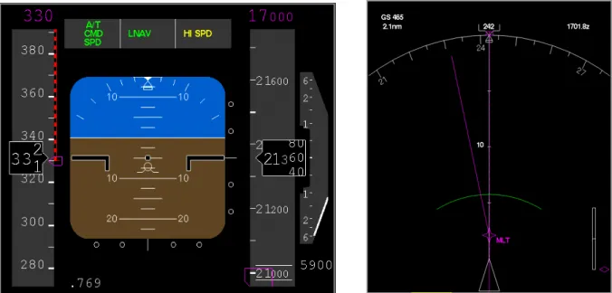
2.2.3 Vertical Channel Feedback
The primary source of vertical channel feedback is the textual display in the Flight Mode Annunciator, in the top middle of the PFD shown in Figure 2.2. In this figure, the aircraft is tracking the ILS glide slope. To the right of the Attitude Determination Indicator, the magenta diamond shows the aircraft deviation above or below the glide slope, indicating, in addition to textually, that the current mode is Glide Slope Tracking. To the right of the altitude tape, the vertical path indicator shows the current descent rate of the aircraft, independent of active mode.
A few graphical elements related to the vertical path are displayed also on the EHSI. The first frame in Figure 2.2 shows a Top of Descent pseudowaypoint about 3 nmi in front of the aircraft. During the descent, an Altitude Intercept Arc (as seen in the second frame) indicates where the aircraft is expected to reach its commanded altitude. The programmed VNAV path is implied by the Top of Descent point, but this actual path is only displayed as a series of text based altitude and speed restrictions on the CDU. Pilots can use the keypad on the CDU to flip through pages of flight segments with associated restrictions and build a mental picture of the aircraft flight path. Unfortunately, in total, the various feedback mechanisms available for the vertical channel do not provide immediate graphical feedback.
2.2.4 Feedback Mechanism versus Channel Complexity
There is also an discrepancy between the feedback available in the vertical channel and the horizontal channel. Though the vertical channel is functionally more complex, there is less feedback to the pilots than in the horizontal. The vertical channel is more complex than the horizontal channel for two reasons: multiple targets and multiple control mechanisms for those
As shown in Table 2.4, the horizontal flight of an aircraft is limited to using a single method to control a single target state: controlling the heading of the aircraft by using the ailerons to for roll authority.
In contrast, the vertical flight of an aircraft requires control of both the speed of the aircraft and its vertical path, since speed and vertical path are interrelated. This leads to the vertical flight of an aircraft having many more potential target states: vertical speed, altitude, preprogrammed vertical flight paths, airspeed, thrust level, aircraft pitch, angle of attack and so on. In addition, each of these targets can be controlled to by a combination of the aircraft pitch and the thrust level. Table 2.5 shows a tally of vertical and speed based flight modes drawn from the MD-11 Cockpit Pilot’s Guide.
As an example, in a simple base mode, such as the Altitude Hold mode, the aircraft speed would be controlled by the throttle and the vertical path (in this case, the altitude) would be controlled by the pitch of the aircraft with the elevators. Another base mode, Flight Level Change mode, sets the throttle at a limit value to control the vertical climb rate, and controls the speed of the aircraft with the pitch.
Table 2.4: Representative Horizontal Modes in the MD-11
Horizontal Modes Control Allocation
Heading Roll
Track Roll
NAV Roll
2.3
Focussed Interviews
Information was gathered via focussed interviews from a variety of informal sources, including direct flight deck observations, discussions with flight crews, and discussions with simulator check airmen about their observations of crews during recurrent training.
Two major conclusions were drawn from these interviews. The first was that the lack of a simple model for the AutoFlight System prompts pilots to create their own ad hoc models. The second was that the vertical channel poses many more problems than the horizontal channel, due to lack of feedback and its greater complexity.
Table 2.5: Representative Vertical and Speed Modes in the MD-11
Vertical and Speed Modes Speed Control Allocation Path Control Allocation
Altitude Hold Throttle Elevator
Altitude Capture Mixed
(MIMO transition)
FMS Altitude Hold Throttle Elevator
FMS Profile Descent Elevator IDLE Throttle
Vertical Speed (MCP) Throttle Elevator
Vertical Speed (FMS) Throttle Elevator
Flight Path Angle Throttle Elevator
Flight Level Change Elevator IDLE or CLIMB Throttle
Glide Slope Tracking Throttle Elevator
Flare Throttle Elevator
Go Around Elevator CLIMB Throttle
Low Speed Protection Elevator Throttle
Based on the analysis of the structure of current AutoFlight Systems, there do not appear to be any simple, consistent, global models for any current AFSs. Such models are not available in flight manuals which instead focus on crew interface and procedures. In the absence of a simple consistent model, pilots appear to develop their own ad hoc models of the AFS as independent parallel SISO control loops. As such, these models may not accurately represent AFS operation, especially in transitions between modes, particularly during automatic transitions. Transitions to and from envelope protection modes also appear to be particularly troublesome.
Since the vertical channel is intrinsically more complex than the horizontal channel, the problems associated with pilot models become exacerbated. In addition since the vertical flight path can be controlled by both pitch and thrust and is linked with the speed of the aircraft, many of the transitions used by in vertical flight involve MIMO control techniques. Pilots do not appear to model MIMO transitions in detail, relying instead on an understanding of the final target state and some smoothness criteria to monitor the AFS performance.
2.4
Improvement of Vertical Channel Feedback
The background research has identified the lack of feedback and a high degree of automation complexity in the vertical channel as a possible source of mode awareness problems. The ASRS report analysis (Section 2.1) showed a majority of incident reports in the vertical/speed mode. The Flight Mode Annunciator (shown in Figure 1.1) depicts the minimal level of feedback currently available for the vertical channel. Finally, the focussed interviews with check airmen (Section 2.3) highlight the complexity of the vertical flight channel. Based on this information it was hypothesized that adding feedback to the vertical channel would mitigate some of the reported and suspected mode awareness problems.
Chapter 3
Electronic Vertical Situation Display
Background research highlighted the vertical channel as an area in need of improved feedback. Based on this hypothesis, a set of crew information requirements was developed. This set of requirements was incorporated into an Electronic Vertical Situation Display (EVSD) to mitigate some of the identified problems.
3.1
EVSD Design
The Electronic Vertical Situation Display is envisioned to provide an analog to the Electronic Horizontal Situation Indicator, which is currently available in glass cockpits. The display is designed to show the programmed vertical path of the aircraft and the modes associated with that path.
The information requirements for the EVSD were created based on operator requirements and
on known mode awareness problems. The information requirements have four major
components: the current mode, any anticipated modes, transitions into anticipated modes, and the consequences of the current state of aircraft automation. The four requirements also provide answers to the most commonly asked questions asked in glass cockpits: “What is it doing?”, “Why did it do that?” and “What will it do next?” (Wiener, 1989). These major aspects of the EVSD are overviewed below, and presented in much greater detail in Section 3.2.
3.1.1 Current Mode
The current mode of the automation needs to be identified along with any of the specific attributes of the mode such as target state values and control allocation. If possible these should be displayed in a graphical format.
3.1.2 Anticipated Modes
Anticipated modes consist of the future modes into which the automation expects the aircraft to transition. Based on some extrapolation of the current aircraft and automation state, the system needs to be able to anticipate future mode transitions and the associated future modes. This determination may be straightforward for many preprogrammed macro modes, but it may be inaccurate for uncommanded mode changes. For example, the highly accurate prediction of entering an envelope protection mode downstream is difficult. Issues associated with anticipation are discussed in Section 3.4.
3.1.3 Mode Transitions and Consequences
Anticipation of the consequences of the current state of the automation is necessary. A predictive profile based on the current automation state should display the locations of anticipated mode transitions and their consequences on the flight path. Determining the location of these transitions requires making assumptions about both the intentions of the pilots and factors external to the aircraft, such as weather and air temperature. Closely related to this is the ability to anticipate mode changes. Since there may not be warning of certain types of mode changes, especially those which are selected by the crew, this may not be possible in all situations.
3.2
EVSD Format
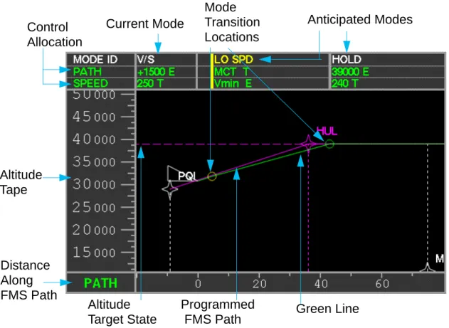
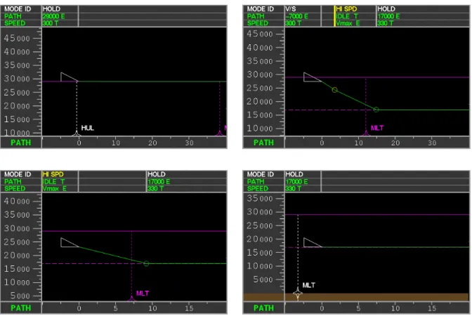
Figure 3.1 shows the prototype EVSD. The display has four distinct areas. At the top of the display is the mode display window, showing the current and anticipated modes, control allocations and target states. At the left is a scalable altitude tape. The bottom window can either display the path distance (if in LNAV mode), or the range directly ahead of the aircraft. Finally, the main window shows the aircraft vertically in relation to the upcoming waypoints and mode transition points.
Figure 3.1: EVSD during Vertical Speed Climb, reaching an envelope protection limit
Current Mode Anticipated Modes
Altitude Target State Mode Transition Locations Green Line Control Allocation Altitude Tape Distance Along FMS Path Programmed FMS Path
3.2.1 Current Mode
In Figure 3.1, the current mode is identified in the top window in green text, directly above the aircraft symbol. Underneath are the control allocations and the target states for the active mode. In this example, the aircraft is in Vertical Speed mode (V/S) with the vertical path controlled by elevator (E) and the speed controlled by throttle (T). An example of a transition criterium is the dashed magenta line at 39 000 ft, which is the altitude dialed into the Mode Control Panel.
3.2.2 Anticipated Modes
On the EVSD, the anticipated mode is shown in the top window above the point where it is predicted to be engaged. The anticipated target state and control allocations are depicted in a manner similar to the current mode. In Figure 3.1, the system is predicting an envelope protection violation and a mode transition to the Low Speed mode (LO SPD). In this mode, the display shows that the vertical path will be controlled by the throttles to Maximum Climb Thrust (MCT), and the speed will be controlled by elevators to Vmin. Note that both the target states and the control allocation change when the new mode is engaged.
Another mode change is anticipated once the aircraft reaches the MCP altitude of 39 000 ft, approximately 40 nmi ahead of the aircraft. The aircraft will switch to Altitude Hold mode (HOLD). Once the automation switches to this mode, the altitude becomes a target state, as shown in the box underneath the HOLD text.
3.2.3 Mode Transitions and Consequences
aircraft will travel based on the current state of the automation. In Figure 3.1, the green line is shown deviating from the solid magenta line as the automation anticipates the aircraft being unable to maintain the commanded climb rate. In this case, an elbow in the path also highlights where the transition is calculated to occur.
The green line also has a set of circles which highlight where the aircraft is going to undergo a mode transition. Green circles depict when the aircraft is going to undergo a programmed mode transition, such as levelling at a commanded altitude as seen in Figure 3.1 near the 40 nmi point. These circles align with the green bars in front of programmed modes shown in the upper window. Yellow circles depict uncommanded or automatic mode changes that occur due to envelope protection violations. In Figure 3.1 the yellow circle at the bend of the elbow highlights the transition at the 5 nmi point to the Low Speed mode (LO SPD). These circles also align with the yellow bars in front of automatic modes in the upper window.
3.2.4 Additional Symbology
A solid magenta line connecting waypoint crossing restrictions is a graphical display of the current vertical path programmed into the FMS. Shown in the main section of the EVSD screen are the waypoints programmed into the FMS. In a manner consistent with the EHSI, programmed waypoints are magenta, and the active waypoint (the one the aircraft is flying to) is white. Non-programmed waypoints are not shown.
Altitude crossings are shown by the altitude of the waypoint symbol. Waypoints without restrictions are placed on the ground, or on the bottom edge of the screen if the ground is not visible. Dashed lines descend to the path scale on the bottom of the display to allow the distance to future waypoints to be easily determined. The horizontal scale is defined by the path distance between each waypoint.
The example shown in the Figure 3.2 is a Vertical Navigation macro mode (VNAV) descent. The aircraft is shown on the first segment of a descent profile using the VNAV mode to maintain an altitude of 12 000 ft. Near the TLG waypoint, the aircraft is anticipated to remain in the VNAV macro mode, but to change the target state at the Top of Descent point (a transition criterium) to a path-based descent. The Aircraft Path Line highlights another mode change that will occur near PQT at 10 000 ft as the aircraft intersects the preprogrammed MCP altitude transition criterium and switches out of VNAV and into an Altitude Hold mode.
Figure 3.2: EVSD in VNAV Descent
Figure 3.3 shows an aircraft close to approach with the additional symbology required near landing. The dashed white line is an indication of the location of the ILS glide slope. At the end of the glide slope is the runway, shown at the correct altitude and length. The difference between waypoints with and without an altitude restriction is also apparent. WAXEN has an altitude restriction associated with it, and is shown at that altitude of 3000 ft. Since there is no altitude restriction associated with the REVER waypoint, it is placed at ground level.
Finally, the very bottom of the main window in the Figure 3.2 has terrain information. While this capability was not used in the experimental evaluation, it has been prototyped on the EVSD.
3.3
EVSD Design Issues
There were several issues which were taken into account in the design of the EVSD. The first was that several assumptions had to be made about the underlying AFS that for which the EVSD was providing feedback. In a related manner, a set of consistent colour symbology had to be selected. Finally, the anticipation capability required for the depiction of future modes had to be carefully designed.
3.3.1 Implementation Assumptions
Three major assumptions were made about the structure and capabilities of the underlying automation. The first was that the underlying architecture of the AFS was able to be represented with a SISO model. Earlier analysis has shown that the AFS appears to be functionally representable by a SISO model for most operating conditions. SISO models also appear to be consistent with pilot models and are currently used on FMAs in some aircraft.
The second assumption was that the system needed to maintain a level of consistency with the current technology level. In order to create a near term solution for current AFS problems, the display was designed to be consistent with current display system limitations and conventions. This also allows pilots to be trained on this display with minimal effort, and with maximum carryover from existing training. This assumption also lead to a set of colour conventions consistent with the Boeing B747-400 Electronic Horizontal Situation Indicator as shown in Table 3.2. Note that the Aircraft Path Line is symbology that is not currently available on the EHSI. This symbology, described in detail in Section 3.2.3, was created in order to have a mechanism to display anticipated mode changes, a capability not currently supported under Boeing conventions.
In a related topic, in order to display anticipated modes, the ability to predict future automation states based on the current flight vector and automation state was assumed. This is
Table 3.4: Color Conventions
Information Element Graphical Representation
MCP Input Dashed Magenta Line
FMS Path Magenta Line
Programmed Waypoint White Symbol
Current Waypoint Magenta Symbol
Mode Transition Point Green Circle
Uncommanded Mode Transition Point Yellow Circle
3.3.2 Anticipation Issues
There are several issues to consider when implementing anticipatory capabilities into aircraft. The biggest concern with reliable anticipation is the varying nature of the flight environment, both externally (winds, temperature) and internally (aircraft weight, configuration, pilot input).
There are also concerns about the non-linearities of aircraft dynamics during mode changes which may make the problem computationally difficult or not readily possible on current generation AutoFlight Systems. At the very least, aircraft may require better sensors, or better noise filtering capabilities. For this implementation of the EVSD, the specific anticipation techniques used are detailed in Section 4.5.
It is important to realize that modern aircraft currently have some level of anticipation capability. Both the altitude capture arc and the flight time determination by FMS involve estimates of the current and future state of the aircraft and provide pilots with input and feedback. Even with limitations, this input is found to be useful. Pilots realize the limitations of the automation (FMS calculates landings late, altitude capture arc moves) and adapt to them. An important consideration is that linear extrapolations improve as the aircraft approaches the transition point. These estimates improve primarily because environmental conditions are closer to those at transition point and the likelihood of unanticipated conditions decreases.
Chapter 4
Prototype EVSD Implementation
The prototype Electronic Vertical Situation Display was implemented on the Aeronautical Systems Laboratory’s Advanced Part Task Simulator. This chapter covers the capabilities of the simulator facility and how they were used in this experiment. The experiment involved using a set of envelope protection features as part of a robust and realistic of AFS architecture. The chapter ends by covering the specifics of the mode anticipation implementation.
4.1
Part Task Simulator Facilities
The experiment was conducted at the MIT Aeronautical Systems Laboratory using the Advanced Part Task Simulator. This facility has been developed over the last seven years by numerous MIT students involved in various aviation human factors and system design experiments.
4.1.1 Simulator Setup
The heart of the simulator facility was a Silicon Graphics, Inc. (SGI) Indigo2 Extreme
Workstation. This machine is interfaced to a Mode Control Panel from a Boeing B737 cockpit, a sidestick controller, a Control Display Unit, and a set of standard aircraft input levers - throttles, landing gear, flaps and speed brakes. A schematic of this setup is shown in Figure 4.1.
The Mode Control Panel was used by the pilot flying as the primary input to the aircraft. The sidestick controller was used by the subject to provide input to the sidetask (detailed in Section 5.4.1). The CDU was primarily used as a mechanism to display altitude restrictions that
experimental runs in which the EVSD was not available as a graphical depiction of this information. Finally, the flap lever on the center panel was used in a number of scenarios to simulate low speed situations during approach scenarios.
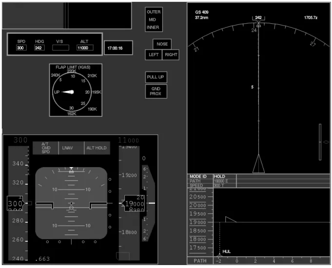
4.1.2 Screen Layout and Display Geometry
As can be seen in Figure 4.2, the prototype EVSD was placed on the simulator screen directly below the EHSI (map mode) display. It was scaled to be as wide as the EHSI and approximately
Figure 4.1: Prototype Part Task Simulator Facility
MODE CONTROL PANEL (MCP)
COURSE IAS/MACH HEADING ALTITUDE VERT SPEED COURSE
CONTROL DISPLAY UNIT
CAGER WENNY WATKI EKR 036 / 16.9 060 / 23.5 076 / 17.4 35000 / 350 30000 / 300 25000 / 250 20000 / 250
SPEED BRAKES, THROTTLES, FLAPS, GEAR PILOT'S CHAIR
CONTROL STICK
A side task is located on the top left of the screen. The side task consisted of centering the position of a moving horizontal gray bar by using a side stick controller. Additional symbology available on the screen was a copy of the Mode Control Panel information (directly below the side task), a flap settings dial and various elements associated with landing: marker lights, gear lights and GPWS warnings. When scenarios were run without the EVSD a blank rectangle appeared where the display was normally located.
4.2
AutoFlight System Capabilities
Since this experiment explored pilot interaction with the simulator AutoFlight System, this section enumerates the capabilities that were available on the simulator which were used for this experimental evaluation.
Standard Modes
The Advanced Part Task simulator is outfitted with a set of AFS modes designed around the terminal area operations for which it has historically been used. In particular, the simulator is outfitted with the vertical modes shown in Table 4.3. Since all of the scenarios were run in an automatic LNAV mode, the lateral modes were not relevant to the experiment.
The simulator is capable of performing changes in altitude in three distinct ways. The first is to have a preprogrammed VNAV path to fly which has an altitude change along the path. The second is to climb at a “climb” throttle setting, or descend at “idle” thrust setting while
Table 4.3: Standard Simulator Modes
Mode Name Functionality
VNAVPATH Vertical Navigation along a preprogrammed path
FLCH Flight Level Change to the commanded altitude
ALT_HOLD Hold the current commanded altitude
VS Maintain the commanded Vertical Speed
GS Follow the ILS glide slope
GS_ARM Arm for capture of the ILS glide slope
Flight Level Change mode. The final mechanism is to command a Vertical Speed (V/S). This vertical speed could fly away from the altitude dialed into the MCP and cause an open descent or climb.
In each case, when the path of the aircraft approaches the MCP altitude, a 0.05g capture maneuver is initiated to smoothly capture the target altitude and automatically transition into an Altitude Hold mode. While in this mode, the simulator uses a variation of the 0.05g arc to maintain the commanded altitude.
The final important mode was the glide slope arming mode, where the AFS was actively searching for a glide slope signal. As soon as the glide slope signal became available, the AFS would engage the Glide Slope (GS) mode.
Envelope Protection Modes
In order to create scenarios with automatic mode transitions due to overspeed and underspeed conditions, two envelope protection modes were used. The first was a High Speed mode, which protected the aircraft from overspeeding by switching the AFS into a speed on pitch, throttle at idle setting similar to the Flight Level Change mode explained in Section 2.2.4. This caused the descent rate of the aircraft to decrease to the maximum descent rate possible on idle throttle while
not gaining speed. This mode was only available in modes where the aircraft was not speed
protected, i.e. modes in which the speed was allowed to vary in order to capture a specific path or
vertical rate. In particular, the envelope protection mode was not available or necessary for the Flight Level Change mode. This mode had a primary speed target and was not constrained to any particular path.
The Low Speed mode was very similar, but switched the aircraft into a speed on pitch, throttle at Maximum Continuous Thrust (MCT) setting again similar to the Flight Level Change mode. The MCT represents the maximum sustainable thrust at altitude.
Finally, a VNAV Speed mode was used to handle situations in which the vertical navigation logic was incapable of flying the programmed path without deviating from the commanded speed by more than 10 knots. This mode placed the aircraft into either a Low Speed or a High Speed equivalent mode depending on whether the AFS was being asked to climb or descend.
Simulator Automation Architecture
It was anticipated that the experimental evaluation of the EVSD would have sessions limited to a few hours per subject. To enable this evaluation, the AFS architecture was designed to be explained quickly and clearly to the subject. Since all of the subjects were expected to have experience in highly automated, modern cockpits, this task was fairly straightforward. In order to create a simple structure, a small set of rules was created and applied to the AFS structure. The outcome of this set of rules detailed in Section 4.3 for the subset of the AFS that was modelled for this experimental evaluation.
4.3
Simulator AutoFlight System Architecture
Designing and implementing a minimal set of rules which defined the AutoFlight System of the simulator solved a number of difficult situations for which satisfactory answers were not available in the open literature. The three rules involved the default state of the aircraft automation, the hierarchy of the constraints and targets input in various manners, and the actions
4.3.1 Default State
There were two basic default states for the aircraft automation, depending on whether the VNAV set of modes were engaged. If VNAV was engaged the AFS would default to VNAV Path, flying to and on the preprogrammed path as soon as it was capable. In situations where the system was forced into VNAV Speed mode, a reversion to VNAV Path would occur as soon as the aircraft levelled off. When not in any VNAV mode, and unless otherwise commanded, the aircraft would remain in its current mode.
4.3.2 Constraint Hierarchy
The overall vertical navigation hierarchy dictated that more immediate modes would override those that were less immediate, or that inner loop modes would override outer loop modes. In particular, anytime the pilot overrode the AutoFlight System and took over manual control, the rest of the AutoFlight System disconnected itself. In addition, any time that a preprogrammed macro mode, VNAV in particular, intersected an inner loop restriction, such as the commanded MCP altitude or the glide slope, the AFS vertical mode would defer to Altitude Hold mode or Glide Slope mode, respectively.
4.3.3 Envelope Protection Modes
Whenever the aircraft AFS was forced into an Envelope Protection mode, it remained in that mode until it intersected a constraint that would allow it to transition to another mode. While in VNAV Speed mode, the aircraft would remain in a descent or climb until it intersected either the commanded MCP altitude (when it would revert to Altitude Hold mode), or until it intersected a level section of the programmed path (when it would revert to VNAV Path mode). When not in VNAV mode, the aircraft would continue on its flight vector until it intersected the commanded MCP altitude.
4.4
Anticipation Capability Implementation
The current implementation of the anticipation capability uses a simplified linear extrapolation to determine what the aircraft is expected to do. The linear extrapolation is based on the current aircraft automation state and operating environment.
The first segment of the linear extrapolation is created based on the instantaneous flight vector of the aircraft until it intersects one of the target states (MCP altitude, VNAV path). Further extrapolation looks forward to a mode change point caused by either an interception of target state (reaching the programmed altitude or waypoint, or interception of the glide slope signal) or anticipates a speed violation based on the acceleration of the aircraft.
Figure 4.4 shows an example of the former type: the aircraft path line continues straight and level until it reaches a target - the waypoint labelled TLG. At that point, it linearly anticipates the next stage of flight, the descent from TLG to POT. At POT, the next target point, the altitude dialed into the Mode Control Panel overrides the VNAV system, and levels the aircraft at
In contrast, Figure 4.5 shows the envelope protection type of anticipation. The speed of the aircraft is dropping as it is forced into an unusually steep climb at a high altitude. This leads to the AutoFlight System anticipating a envelope protection transition into the Low Speed mode relatively soon. From that point forward, the well defined Low Speed mode operating characteristics are used to anticipate the next segment of the aircraft’s flight.
Chapter 5
Experimental Design
The performance of AutoFlight System monitoring with a standard set of displays was compared to the performance when standard displays were augmented with the Electronic Vertical Situation Display by performing an experiment using the Aeronautical Systems Laboratory’s (ASL) Part Task Simulator. This chapter described the experiment design and the data analysis used in this study. Both performance and subjective measures were used in the evaluation process. The experimental overview is presented followed by the procedural protocol and the performance measures.
5.1
Experiment Overview
The overall approach to this experiment was to have subject (current “glass cockpit” airline) pilots act as Pilot Not Flying (PNF) and observe a set of scenarios running on the ASL Part Task Simulator. While subjects observed the scenarios, the researcher acted as Pilot Flying (PF), interacting with the simulated aircraft automation and responding to prerecorded Air Traffic Control directives. Both the subject and the researcher were located in from of identical displays (shown in Figure 4.2) to simulate the set of instruments available to the captain (subject) and first officer (researcher) in an actual cockpit. Both displays were electronically slaved together to show identical information at all phases of the experiment. If during the course of the scenario the subject felt that some sort of mode event (as detailed in Section 5.3.1) occurred, they pressed a button on the side stick controller and articulated their concern. This audio data was later analyzed for timing and content.
During experimental design it was found that simply monitoring the displays was an unrealistic representation of the workload in actual cockpit operations. To correct this, subjects were given an unrelated side task to monitor.
This evaluation methodology is very similar to the SAGAT situational awareness technique (Endsley, 1995) with some implementation differences. In contrast with SAGAT evaluations, where the subjects actively interact with the simulator, the EVSD evaluation scenarios were completely passive for the subjects. The only interaction was for the subjects to articulate concerns at any point during the evaluation that they felt necessary.
5.2
Test Matrix
The design of the test matrix included only one independent variable: the availability of the EVSD. This led to each scenario being run at least twice, once with and once without the display.
In order to prevent pilots from recognizing a scenario the second time they were exposed to it, two full sets of scenarios were constructed. At a minimum, scenarios that address the same mode awareness problem were set in a different geographic airspace with different associated altitudes, ATC clearances, timing conditions and waypoints.
In addition, to prevent pilots from expecting every scenario to have a mode error, some scenarios were created which did not have mode events. These “placebo” scenarios, which made up one third of the scenarios, were scattered throughout the experimental run.
order. In addition, to minimize problems with varying the scenario order between runs, half of the subjects had one set of scenarios first; the second half had the other set first. As shown in Table 5.1, the total of eight subject allowed two complete test matrices to be filled.
5.3
Performance Measures
Three separate performance measures were used in this study. The first was an objective measure of the time it took subjects to respond to the incident. Secondly, a questionnaire was filled out by each subject after each scenario. Finally, after all the scenarios had been completed, subjects filled out a summary questionnaire as an overall evaluation of the EVSD.
5.3.1 Subject Input
During the scenario, the subject had access to a Push to Talk button which signaled the computer to record their voice as well as the time at which the signal was sent. Subjects were instructed to signal the computer at any time they would normally discuss a problem with the
Table 5.1: Test Matrix
Subject Number First Scenario Set EVSD Second Scenario Set EVSD
1 1 Y 2 N 2 2 N 1 Y 3 1 N 2 Y 4 2 Y 1 N 5 1 Y 2 N 6 2 N 1 Y 7 1 N 2 Y 8 2 Y 1 N
other pilot, or any time they felt it necessary to discuss the operation and performance of the aircraft. Pilots were explicitly instructed to signal they computer when they felt that a mode event occurred as defined as either:
1. An uncommanded mode transition had occurred 2. An error had been made in interfacing with the FMS 3. An unsafe or nonprocedural operation had taken place
At this point, subjects were instructed to articulate the reason that the button was pressed and explain the situation to the best of their ability. Subjects were instructed to use the Push to Talk button as a tool to communicate problems to ATC, or to the PF. In addition to recording timing information, this mechanism also recorded the subject’s statements for future analysis. The scenario continued during and after the recording, until the scenario was completed. After the scenario was completed, the display blanked and the subject answered a series of questions designed to determine the level of mode and situational awareness.
5.3.2 Objective Measures
The objective measures were based on the elapsed time between the mode event and the pilot response or, when relevant, the net altitude deviation the aircraft from the intended path. The latter indication was used when the altitude deviation of the aircraft was the relevant factor in the incident.
5.3.3 Subjective Measures
After each scenario, subjects were asked questions which addressed the cause of the mode transition, the consequences of the new mode state and the cues used by the subject to determine that an incorrect automation state was reached.
1. Why did you stop the scenario?
2. What caused the event? Why did it happen?
3. What cues did you use to determine that the event occurred?
4. What would have eventually happened if you had not stopped the scenario?
These questionnaires were then rated to determine the level of the subject’s understanding of the problem. Each rating corresponded with differing levels of comprehension:
1. Did not react to or understand mode event 2. Reacted procedurally to mode event 3. Understood mode event
In order to determine in a objective manner whether pilots understood the underlying cause of the incident, each scenario had a key element that was deemed to be indicative of understanding. These elements are detailed in Section 6.2 along with the scenarios themselves.
5.3.4 Post Experiment Questionnaire
In addition, after the experiment was completed, subjects filled out a survey comparing the EVSD enhanced AutoFlight system to the regular AutoFlight System. An example of this survey is shown in Appendix A.
5.4
Subject Selection and Training
Subject were local pilot volunteers who had experience flying highly automated glass cockpit aircraft, in particular the Boeing B757/B767. Since subjects were volunteering time to the experiment and were a self-selected group, results may be skewed in the favour of pilots who are interested in new technology in the cockpit.
To train subjects, they were first given an overview of the basic instrumentation on the simulator, including the map display (EHSI), the primary flight display, and the B737 Mode Control Panel. Subjects were also trained to the specifics of the AutoFlight System simulated on the computer. These specifics included the inclusion of envelope protection and the VNAV Path to VNAV Speed mode change if the aircraft varied more than 10 kts from the target speed in VNAV mode.
Since the simulator is not aircraft specific, subjects were allowed to familiarize themselves with the mixed display conventions. They were also shown how to use the control stick to interact with the side task, and how and when to use the Push to Talk button to record mode events. In addition, subjects were given a complete demonstration of the capabilities and display conventions of the EVSD in detail, to allow familiarization. Subjects were then flown through a set of three training scenarios.
Before each scenario, subjects were briefed on the state of the aircraft and automation. An example of this briefing would be: “The aircraft is straight and level at FL210, and is waiting on a climb directive from ATC to FL 350. We’re in LNAV, and Altitude Hold. Airspeed is 300 kts
Once the scenario began, subjects were instructed to always use the Push to Talk button to interact with the researcher (Pilot Flying), or with ATC to assure that any conversations were recorded for later analysis. The researcher acted as the sole PF and responded to the prerecorded Air Traffic Control cues that occurred at various times during the scenarios. The PF also handled all of the interaction with the MCP and scaled the displays to ensure that the relevant information was always available.
5.4.1 Side Task
In order to maintain a level of pilot workload, subjects are also given a side task. The side stick controller is used to provide input to an indicator bar as it varies based on a Markov turbulence model. This side task is located on the top left corner of Figure 4.2. The goal was to keep the grey bar centered within the green level lines.
The intent of the sidetask was to increase the workload of the pilot to a more realistic level by requiring them to break their regular scan pattern in order to deal with the varying indicator bar. Subjects were instructed to attend to the side task when they felt they had time, but not at the expense of monitoring the aircraft.
5.5
Scenario Design
In order to evaluate the effect of the prototype EVSD on mode awareness a representative series of experimental scenarios were developed based on a sampling of common mode awareness problems that were found in the ASRS review and in the open literature. The scenarios are described in Chapter 6 along with the results of the evaluation.
Chapter 6
Scenario Descriptions and Evaluation Results
The purpose of this experiment was to investigate the relative differences in pilot performance when an Electronic Vertical Situation Display augmented a standard glass cockpit and when such as display was not available, in terms of both performance and subjective evaluations. This chapter reports the results of the experiment: profiles of the subjects, results of individual scenarios, and finally the overall subjective evaluation of the display.
6.1
Profile of Subjects
A total of eight subjects participated in this experimental evaluation. The subject ranged in ages from 39 to 53 with a mean age of 47. First officers comprised 62.5% of the subjects; the remaining 37.5% were captains. 37.5% were initially trained as civil pilots, while the remainder were initially trained by the military.
Subjects had between 4000 and 15870 hours of civilian flight experience with a mean of 8646 hours. Between 200 and 5000 of these hours were in glass cockpits, with a mean of 2263 hours. Estimated flight hours in 1995 ranged between 250 and 800 with a mean of 533 hours.
6.2
Scenario Descriptions and Results
The bulk of the scenarios have results based on objective timing information. Two of the scenarios (Target Error by Pilot Flying during Non-precision Approach and the Altitude Capture Failure during Altitude Change) use the net altitude deviation as a more relevant measure, as it is of greater merit. In this context, negative altitude deviations refer to pilots reporting the incident
before they reached the point at which an altitude deviation would occur. Similarly, negative times refer to pilots anticipating the incident and reporting it before it would occur, with the absolute value of the time indicating the anticipation time.
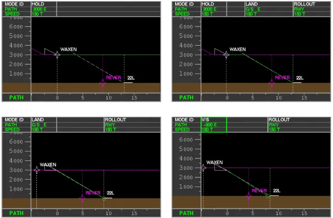
6.2.1 Glide Slope Transmitter Failure during Approach
This scenario simulated the loss of the ground based glide slope transmitter during an AFS flown Instrument Landing System (ILS) approach.
Description
As shown in the first frame of Figure 6.1, the aircraft starts this scenario close to the airport, at
a low altitude, and with flaps in a semi-extended setting (15°). In the second frame, the Pilot
Flying engages both the Glide Slope Capture and the Localizer Capture logic in the AFS. A few seconds after the glide slope is captured in the third frame, the ground based transmitter fails. This failure results in a loss of signal to the aircraft system, causing a mode reversion to Vertical Speed mode with the current (instantaneous) vertical speed as the target criterium as seen in the final frame.
This mode reversion is common in AFS designs because it maintains the instantaneous speed to allow easy recapture of the glide slope in situations where the signal is momentarily interrupted due to ground reflections or shadowing by other aircraft. The cues that normally show that the aircraft’s receiver has failed (crosses over the glide slope information areas on the PFD) are not shown, because the aircraft based equipment continues to function normally. After the aircraft transitions into Vertical Speed mode and the flight path trajectory intersects the ground short of the runway threshold.
Mode Event Cues
EVSD-specific cues include a change in the mode header and the green path prediction line indicating the dangerous flight path as shown in the final frame of Figure 6.1.
Without the EVSD, cues include the disappearance of the magenta diamond on the glide slope indicator, and the FMA and the MCP reverting to a vertical speed mode. In the first frame of Figure 6.2, the PFD is shown just before the glide slope signal is lost. In the second frame, the
loss of signal is shown by the lack of a magenta glide slope tracking diamond on the scale to the left of the Attitude Determination Indicator (ADI), and by the change in the active mode of the aircraft from G/S to V/S.
The key element to understanding this scenario was for the subjects to realize that an equipment failure occurred and that the glide slope signal had been lost and that the new flight path landed short of the runway.
Results
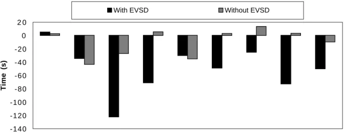
Figure 6.3 shows that by using the EVSD, subjects noticed and reacted to this mode event 17.2 seconds sooner than without at a confidence level of 80%. This is interesting in that the only changes on the EVSD during this scenario are the shift in the green line and the flashing and alteration of the text displayed in the mode header.
Pilot understanding of the scenario was slightly different with the EVSD as seen in Figure 6.4. One subject recognized the reversion to a Vertical Speed mode, but completely failed to notice the event in terms of landing short of the runway. While the subject called for a Go Around due to loss of glide slope, he failed to realize the immediate implications of the mode event.
Figure 6.3: Glide Slope Transmitter Failure during Approach: Timing Results
Figure 6.4: Glide Slope Transmitter Failure during Approach: Subject Understanding Ratings
0 1 0 2 0 3 0 4 0 5 0 6 0 7 0 8 0 9 0
Subject 1 Subject 2 Subject 3 Subject 4 Subject 5 Subject 6 Subject 7 Subject 8 Mean
Time (s)
With EVSD Without EVSD
0 2 4 6 8 Did Not Understand Mode Event Reacted Procedurally to Mode Event Understood Mode Event Number of Pilots With EVSD Without EVSD
6.2.2 Overspeed Envelope Protection during Altitude Change
A late ATC directive leads to a high vertical descent rate, which engages the envelope protection of the aircraft.
Description
The first frame in Figure 6.5 shows the aircraft beginning the scenario at a high altitude and at reasonable speed. The subject is instructed that they are waiting for an ATC clearance to descend to the next waypoint. When the clearance is finally given, it is an urgent request (“ASL123,