Winding Brushless Doubly Fed Reluctance Generators
The MIT Faculty has made this article openly available.
Please share
how this access benefits you. Your story matters.
Citation
Zhang, Fengge; Zhu, Liancheng; Jin, Shi; Cao, Wenping; Wang,
Dairui and Kirtley, James L. "Developing a New SVPWM Control
Strategy for Open-Winding Brushless Doubly Fed Reluctance
Generators." IEEE Transactions on Industry Applications 51, no. 6
(July 2015): 4567-4574.
As Published
http://dx.doi.org/10.1109/TIA.2015.2461614
Version
Author's final manuscript
Citable link
http://hdl.handle.net/1721.1/108429
Terms of Use
Creative Commons Attribution-Noncommercial-Share Alike
Developing a New SVPWM Control Strategy for Open-Winding
Brushless Doubly-Fed Reluctance Generators
Fengge Zhang
1, Liancheng Zhu
1,2, Shi Jin
1, Wenping Cao
3,4, Senior member, IEEE, Dairui Wang
1,5,
James L. Kirtley
4, Life Fellow, IEEE
1 Shenyang University of Technology, Shenyang, P. R. China, 110870
2 University of Science and Technology Liaoning, Anshan, P. R. China, 114051. [email protected]
3 Queen’s University Belfast, Belfast, U.K. BT9 5AH
4 Massachusetts Institute of Technology, Cambridge, MA U.S.A. 02139
5
Huawei Technologies Co., Ltd, Shenzhen, P. R. China, 518129
Abstract -- In this paper, a new open-winding control strategy
is proposed for a brushless doubly-fed reluctance generator
(BDFRG) used for standalone wind turbine or ship generators.
The BDFRG is characterized with two windings on the stator: a
power winding and a control winding. The control winding is
fed with dual two-level three-phase converters, and a vector
control scheme based on space vector pulse width modulation
(SVPWM) is designed. Compared to traditional three-level
inverter systems, the dc-link voltage and the voltage rating of
power devices in the proposed system are reduced by 50% while
still greatly improving the reliability, redundancy and fault
tolerance of the proposed system by increasing the switching
modes. Its performance is evaluated by simulation in
MATLAB/SIMULINK, and an experimental study on a 42-kW
prototype machine.
Index Terms--Brushless doubly-fed reluctance generator
(BDFRG), dual two-level converters, open-winding, space vector
pulse width modulation (SVPWM).
I. I
NTRODUCTIONThe penetration of wind power into the power system is
continuing to grow across the world [1]-[4], with an aid of
rapid development of machine technologies, power
electronics and automatic control
.
The brushless doubly-fed machines are the evolution of the
cascaded induction machine [5]-[13], and are widely used for
medium and large wind turbines. Among them, brushless
doubly-fed reluctance generators (BDFRGs) are a promising
topology owing to their robust rotor [14]-[17]. As shown in
Fig. 1(a), a typical BDFRG consists of two sets of stator
windings: a power winding and a control winding. Since the
rotor winding is moved to the stator as the control winding,
the brushes and slip-rings in conventional doubly-fed
machines are eliminated. Therefore the robustness and
reliability is improved. However, the technical challenges lie
in the rotor design where the double stator magnetic field
This work was supported by National Science Foundation of China (51277124), Specialized Research Fund for the Doctoral Program of Higher Education (20122102110004), Education Department of Liaoning Province (L2012027), the Seventh Framework Programme of the European Union (FP7) project “EDWTGT–Evaluation and Development of Wind Turbine Generator Technologies” (318925), and Youth Foundation of University of Science and Technology Liaoning (2012QN29).
modulation is realized; and the control of the converters,
which manipulates the flow of active and reactive power, and
power factor regulation through power winding or the control
winding [5]-[8]. The converters are of about 25% of the
machine’s rated power to control a wide speed range at
various operating modes including super-synchronous,
synchronous and sub-synchronous. Compared with the
doubly-fed induction machine and permanent magnet
synchronous machine, the BDFRG is better suited for wind
turbines, shaft generators, pumps, and hydropower generation
systems [9]-[17].
In references [5]-[18], a BDFRG and its power generation
systems were analyzed by scalar control, vector control, and
the power flow analysis. It is well known that traditional
three-level converter systems have some disadvantages [19],
[20], such as complex structure, high voltage of DC link and
power devices, and the potential shift of neutral point voltage.
In order to improve these, some variable-speed
constant-frequency (VSCF) schemes were proposed [12]-[17],
[21]-[23]. As shown in Fig. 1(b), where have some obvious
advantages compared with the previous generator system, i.e.,
the control winding of the BDFRG is open-circuited and fed
with dual two-level converters, and the space vector pulse
width modulation (SVPWM) coordination control strategy is
adopted, then the reliability, redundancy and fault tolerance
of the proposed system are greatly improved while the
dc-link voltage and the voltage rating of power devices are
reduced by 50%.
wind turbine BDFRG Grid (50Hz) control winding pc, fc power winding pp, fp M S C G S Cgear +
(a)
BDFRG Grid (50Hz)
gear wind turbine power winding pp, fp control winding pc, fc M S C 1 M S C 2
+ GSC (b)
Fig. 1. Schematic diagram of the BDFRG. (a) Traditional topology, (b) The proposed topology.
II. O
PEN-W
INDINGC
ONTROLS
TRATEGY OFB
RUSHLESSD
OUBLY-
FEDG
ENERATORA. The Principle of VSCF Based on BDFRG
The BDFRG is a new type of machine developed in recent
years [7]; its stator has two sets of stator windings with two
different pole numbers. The primary winding (also known as
the power winding) is directly connected to the grid and the
secondary winding (also known as the control winding) is fed
through the converter, as shown in Fig. 1. The relationship
between frequency, pole pairs and operating speed of the
BDFRG is given by:
(
)
60
r p c p cn p
p
f
=
+
± (1)
f
where f
pis the supplied line frequency (also known as the
frequency of power winding); n
ris the rotor speed in rpm; p
pand p
care the pole pair of the power and control windings,
respectively; f
cis the converter frequency (also known as the
frequency of control winding).
Obviously, the BDFRG is suited for VSCF operations and
its application includes wind turbines, shaft generators and
hydroelectric generators.
B. Mathematical Model of BDFRG
For control implementation, the voltage balance equation
in a rotating reference frame [8] is expressed as (2), and the
flux equations is expressed as (3),
(
)
(
)
(
)
(
)
(
)
(
)
(
)
(
)
(
)
(
)
qp p qp p qp pc qp pc qp qc dp dp p dp p dp pc dp pc dp dc qp qc c qc c qc pc qc pc qc qp r dc dc c dc c dc pc dc pc dc dp r qcu
r i
p L i
L i
p L
i
i
u
r i
p L i
L i
p L
i
i
u
r i
p L i
L i
p L
i
i
u
r i
p L i
L i
p L
i
i
ωψ
ωψ
ω ω ψ
ω ω ψ
⎡
⎤
=
+
−
+
⎣
−
⎦
+
⎡
⎤
=
+
−
+
⎣
+
⎦
−
⎡
⎤
=
+
−
+
⎣
−
⎦
+
−
⎡
⎤
=
⎧
⎪
⎪
⎪
⎨
+
−
+
⎣
+
⎦
−
−
⎪
⎪
⎪⎩
(2)
qp p qp pc qc dp p dp pc dc qc c qc pc qp dc c dc pc dpL i
L i
L i
L i
L i
L i
L i
L i
Ψ
Ψ
Ψ
Ψ
=
−
⎧
⎪
=
+
⎪
⎨
=
−
⎪
⎪
=
+
⎩
(3)
where the letter “p” denotes the differential operator, the
subscripts “d” and “q” denote the d-axis and q-axis
components; “p”, “c” and “r” denote the power winding,
control winding and rotor components, respectively. ω is the
speed of the rotating coordinate system, ω
rdenotes the rotor
angular speed, L
pcis the mutual inductance between power
and control winding.
The electromagnetic torque is expressed as (4) and (5) [11],
2
3(
)
sin
2(
)
p c p em p pc p c pcp
p L
T
L L
L
δ
+
=
−
Ψ Ψ
(4)
d
d
r em L d rT
T
K
J
t
ϖ
ϖ
− −
=
(5)
where Ψ
pand Ψ
pcdenote the flux linkage of power winding
and mutual flux linkage between power and control winding,
and δ is the angle between them. T
emdenotes the total
electromagnetic torque, T
Ldenotes the load torque, J denotes
the moment of inertia, K
ddenotes the rotary system damping
coefficient.
C. The Control Strategy of BDFRG
Also in Fig. 1, the wind turbine will drive the rotor to rotate,
where the power winding is directly connected to the grid or
load, and the control winding is connected between two
bi-directional converters and then to the grid. During an
operation, the control winding is fed with the machine side
converter (MSCs) supplied by the grid side converter (GSC)
to generate a magnetic field. When the BDFRG is driven by
the wind turbine, power is generated for the grid, load, or
charging the battery. In Fig. 1(b), the dotted box represents a
control topology for the dual two-level converters, which is
further shown in detail in Fig. 2, where the control winding is
open-circuited (thus the machine is termed the open-winding
BDFRG, OWBDFRG), and fed with two reversible
converters (MSC1 and MSC2) supplied by one DC bus and
by combining dual two-level converters, can form a
three-level converter while the DC bus voltage (U
dc/2) is only half
of traditional three-level converter (U
dc) [19]-[20], as shown
in Fig. 3. That is, by using the open-winding control strategy,
the capacitance of the DC-link and the voltage rating of
power devices can be decreased. When compared with
typical two-level converters, the open-winding control
strategy increases the converter voltage step level so that the
switching power losses are also reduced. If one of the two
MSCs is faulted or disconnected, the system can still operate
with the remaining MSC.
control winding MSC1 1 3 5
4 6 2 o + 1' 3' 5'
4' 6' 2' + o MSC2 c1 c2 b1 b2 a1 a2 + + dc 4 U dc 4 U dc 4 U dc 4 U
Fig. 2. The system diagrams of the OWBDFRG.
For the OWBDFRG shown in Fig. 2, the instantaneous
voltages of the control winding can be found as (6), (7).
1 2 1 2 1 2 1 2 1 2 1 2 ca a O a O a a cb b O b O b b cc c O c O c c
u
u
u
u
u
u
u
u
u
u
u
u
=
−
=
⎧
⎪
=
−
=
⎨
⎪
=
−
=
⎩
(6)
MSC1 MSC2 c=
−
u
u
u
(7)
D. SVPWM Coordination Control Strategy
The SVPWM control strategy, also called the flux sine
PWM control, uses the output voltage of the three-phase
inverter in different switching modes to approach to the
inscribed circle of the corresponding regular polygon, then
the sine round rotating magnetic field is obtained with a
constant amplitude in the machine, the advantages of
SVPWM and constant flux control can be realized.
In Fig. 2, the phasor diagram of two-level converter
(MSC1, MSC2) is shown in Fig. 4, where the hexagon vertex
respectively to 1-6 and 1'-6', and the space is divided into six
sectors, the effective voltage space vector is U
1-U
6and U
1'-U
6'(1-6 and 1'-6', respectively), which the mode is U
dc/3,
zero vector is of U
7, U
8, U
7'and U
8'(7, 8, 7' and 8',
respectively). Traditionally, the maximum switching mode is
2
3=8 in a two-level three-phase converter and 3
3=27 in a
three-level converter [19]-[23], as shown in Fig. 3. By
cascading the dual two-level converters (see Fig. 2), the
switch modes in the proposed converter can increase to
2
3×2
3=64 (see Fig. 5(a)). Obviously, the redundancy and fault
tolerance of the proposed topology are improved.
The diagram of the voltage space vector with a dual
two-level converter is shown in Fig. 5 (a), where the synthesis 64
voltage space vector is 11'-88'. The control space is divided
into 24 small sectors or one inner hexagon and six outer
hexagons, i.e., ABCDEF is the inner hexagon with its center
of O, six outer hexagons are OFSGHB, OAHIJC, OBJKLD,
OCLMNE, ODNPQF and OEQRSA, with their midpoints of
A-F. In this paper, the two reference voltage space vectors are
chosen for the two converters (MSC1, MSC2).
MSC1 ref MSC2 ref
1
2
1
2
⎧
=
⎪⎪
⎨
⎪
= −
⎪⎩
U
U
U
U
(8)
U
MSC1, U
MSC2and U
refdenotes the voltage vector of MSC1,
MSC2 and the reference voltage of the control winding,
respectively, as shown in Fig. 5(b).
It is needed to make sure that the two voltage vectors have
the same amplitude as the reference voltage phasor (half of
the reference voltage vector).
Assuming that the reference voltage vector U
reflies in △
IOG, as shown in Fig. 5(b), corresponding to Fig. 4(a) which
lies in sector 1 for MSC1, and (b) lies in sector 4 for MSC2.
In Fig. 4(a), due to the parallelogram law, the reference
voltage vector U
MSC1consists of two adjacent effective
vectors U
1, U
2, and zero vector U
O, and the operating time
can be calculated [22], [23].
a b c Udc control winding P dc 2 U dc 2 U io N + O N + (a) 20(NPN) 1(PPP) 4(POO) I O A B C S D E F G H J K L M N P Q R 2(OOO) 3(NNN) 5(ONN) 6(PPO) 7(OON) 8(OPO) 9(NON) 14 13 12 11 15 16 17 18 19 20 21 22 23 24 12(OOP) 13(NNO) 10(OPP) 11(NOO) 14(POP) 15(ONO) 16(PNN) 17(PON) 18(PPN) 19(OPN) 21(NPO) 22(NPP) 23(NOP) 24(NNP) 25(ONP) 26(PNP) 27(PNO) 8 2 1 3 4 5 6 7 9 10 (b)Fig. 3 Topology of BDFRG fed by NPC three-level converter. (a) Topology, (b) Voltage space vector.
1' (100) α θ ○1 UMSC1 1 (000) 2(110) 3(010) 4 5(001) 6(101) (111) 8' 2'(110) 3'(010) 4' 5'(001) 6'(101) 7' (011) (100) (011) θ ○2 7 8 ○3 ○4 ○5 ○6 (111) (000) ○1 ○2 ○3 ○4 ○5 ○6 Udc/2 Udc/2 β α β UMSC2 (a) (b) Fig. 4. The space phasors in each inverter. (a) MSC1, (b) MSC2.
88' 78' 74' 66' 11' 55' 71' 44' 85' 73' 72' 77' 83' 56' 32' 86' 75' 12' 65' 81' 33' 76' 87' O B A C D E F F G H I J K L M N P Q R S 22' 84' 13',64' 36' 35',26' 38' 14' 18' 17' 15',24' 16' 21' 23' 25' 27' 28' 31',46' 37' 34' 45' 43' 82' 51',42' 41' 47' 48' 52' 53',62' 54' 57' 58' 61' 63' 67' 68'
c
a b βα
(a) ○7 ○1 ○4 Uref UMSC2 ○2 ○3 ○5 ○6 ○9 ○10 ○8 ○11 ○12 ○13 ○14 ○15 ○16 ○17 ○18 ○19 ○20 ○22 ○21 ○23 ○24 O B A C D E F F G H I J K L M N P Q R S UMSC1c
a
b
β
α
(b)Fig. 5. The space phasors of proposed dual two-level converters. (a) Voltage phasors, (b) Relationship between MSC1, MSC2 and reference voltage vector.
III. S
IMULATIONR
ESEARCH ON THEC
ONTROLS
TRATEGYA. The Simulation Model of the Control System
The simulation model of the proposed system is established
in MATLAB/SIMULINK, as shown in Fig. 6, where includes
a OWBDFRG, a resistive load, a reference speed n
r*,
frequency calculation (f
c), static three-phase coordinates/
rotary two-phase coordinates transformation (3s/2r), rotary
two-phase
coordinates/static
two-phase
coordinates
transformation (2r/2s), control strategy of constant voltage
frequency ratio (U/f), the SVPWM scheme.
During the operation, according to the reference speed n
r*of generator rotor, and line frequency of 50 Hz, the required
frequency and voltage of control winding is calculated in
real-time, i.e., by the machine side dual two-level converters
with SVPWM coordinated control, then the voltage and
frequency required by the dual MSCs can be generated.
B. Analysis of Simulation Results
The generator parameters as: P
N=42kW, U
N.p=U
N.c=380V,
p
p=3, R
p=0.1662 Ω, L
p=0.01737 H, L
pc=0.01813 H, p
c=1,
R
c=0.1882 Ω, L
c=0.02351 H, J=0.3 kg.m
2.
In order to validate the effectiveness of the proposed
topology in VSCF, the simulation is firstly carried out at the
speed of 606, 750, and 789 rpm, corresponding to
sub-synchronous, sub-synchronous, and super-synchronous modes of
the BDFRG. Simulation results are shown in Figs. 7-10. Fig.
7 shows the voltage reference in phase a of the control
winding according to the VSCF generation, Figs. 8-10 show
the phase voltage, line voltage and current of the control
winding, respectively. As can be seen from these figures, the
proposed SVPWM three-level control strategy in
open-winding brushless doubly-fed reluctance generator is
effective.
OWBDFRG control winding (open winding) pc, fc power winding pp, fp MSC2 MSC1 + +2 dc U
2 dc U three- phase resistive load nr*
electric angle (1) fc Uref (U/fc) two series of u-i control ωr*t two series of 3s/2r ud* uq* ud1, uq1 id1, iq1 ud2, uq2 id2, iq2 two series of SVPWM two series of 2r/2s ud1, uq1 ud2, uq2 uα1 uβ1 uα2 uβ2 three-phase u-i measurement rotor u i
Fig. 6. The simulation diagram of the proposed control scheme.
Time (s) (a)
Time(s) (b) Fr eq ue nc y (H z) f p fc 0 2 4 6 8 10 -5 10 25 40 55 Sp ee d (r pm ) nr* nr 0 2 4 6 8 10 600 650 700 750 800
Time (s) (c) Time (s) (d) Time (s) (e)
Harmonic order (N) (f)
Fig. 7. Simulation results in PW, CW. (a) nr*, nr, (b) stator frequency of PW, CW, (c) reference voltage of control winding, ucaref, (d) enlarged vision of (c), (e) voltage of power winding in phase a, upa, (f) FFT analysis of upa.
Time (s) (a) Time (s) (b) Time (s) (c) Time (s) (d) Time (s) (e)
Fig. 8. The voltage waveform in phase a of control winding, (a) full speed range, (b) sub-synchronous (606 rpm), (c) enlarged vision of (b), (d)
super-synchronous (789 rpm), (e) enlarged vision of (d).
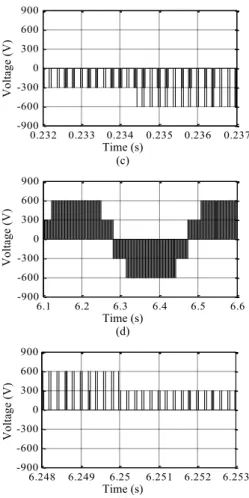
Time (s) (a) Time (s) (b) Vo lt ag e (V) 0.2 0.22 0.24 0.26 0.28 0.3 -900 -600 -300 0 300 600 900 Vo lt ag e (V) 0 2 4 6 8 10 -900 -600 -300 0 300 600 900 Vo lt ag e (V) 6.248 6.249 6.25 6.251 6.252 6.253 -450 -300 -150 0 150 300 450 Vo lt ag e (V) 6.1 6.2 6.3 6.4 6.5 6.6 -450 -300 -150 0 150 300 450 Vo lt ag e (V) 0.232 0.233 0.234 0.235 0.236 0.237 -450 -300 -150 0 150 300 450 Vo lt ag e (V) 0.2 0.22 0.24 0.26 0.28 0.3 -450 -300 -150 0 150 300 450 Vo lt ag e (V) 0 2 4 6 8 10 -450 -300 -150 0 150 300 450 Vo lt ag e (V) 1 1.1 1.2 1.3 1.4 -80 -40 0 40 80 Vo lt ag e (V) 0 2 4 6 8 10 -80 -40 0 40 80 Vo lt ag e (V ) 2 2.02 2.04 2.06 2.08 2.1 -400 -200 0 200 400 0 2 4 6 8 10 12 14 16 18 20 0 25 50 75 100 Ma g (% of F unda m ent al ) Fundamental (50Hz) = 310.8, THD= 1.14%
Time (s) (c) Time (s) (d) Time (s) (e)
Fig. 9. The line voltage waveform between phase a and b of control winding. (a) full speed range, (b) e sub-synchronous (606 rpm), (c) enlarged vision of (b), (d) super-synchronous (789 rpm), (e) enlarged vision of (d).
Time (s) (a)
Time (s) (b)
Fig. 10. The current in phase a of control winding. (a) Sub-synchronous (606 rpm). (b) Super-synchronous (789 rpm).
IV. E
XPERIMENTALR
ESULTSThe proposed control strategy is implemented and
executed in DSP28335 in a semi-physical simulation
experimental platform as shown in Fig. 11, where includes a
prime mover of the induction motor (IM), OWBDFRG,
resistive load, converter (15 kW), power analyzer, thermal
imager, and so on.
The experimental results in the sub-synchronous and
super-synchronous modes (n
r*=606 and 789 rpm, respectively)
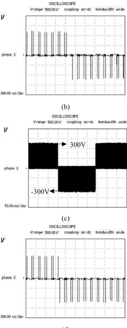
are shown in Figs. 12-15. Figs. 12-13 present the control
winding voltage waveforms, where Fig. 12-13(a) and (c) are
the voltage in phase a and line voltage between phase a and b,
Figs. 12-13(c), (d) are their enlarged visions, which are all
corresponding to Fig. 8-9, and are same to the voltage of
traditional three-level converter. Fig. 14 shows the current in
phase a of control winding, which also corresponds to Fig. 10.
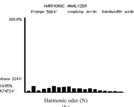
Fig. 15(a)-(b) demonstrates the power winding voltage in
phase a and its Fourier analysis result. The phase voltage is
about 224 V, 50 Hz, the THD is 3.7%, and the third harmonic
voltage is 4.747 V, which satisfying the VSCF requirements.
From the above analysis of experimental results as shown
in Fig. 12-15, we can obtain that the new SVPWM strategy of
proposed OWBDFRG fed with dual two-level converters is
correct and valid, the control effectiveness and feature are the
same to the traditional three-level converter, which is of
three-level phase voltage and five-level line voltage, while
the dc bus voltage is lower than three-level converter, the
reliability, redundancy and fault tolerance of the proposed
system are greatly improved, but does not have the traditional
three-level converter disadvantages, such as complex
topology, potential deviation of neutral point, and so forth.
(a) (b)
Fig. 11. The semi-physical simulation experimental platform. (a) The BDFRG, IM and resistive load, (b) The converter.
(a) resistive load BDFRG IM converter power analyzer thermal imager connecting terminal -300V 300V 11.7A Cu rr en t ( A ) 2 2.1 2.2 2.3 2.4 2.5 -15 -10 -5 0 5 10 15 Vo lt ag e (V) 6.248 6.249 6.25 6.251 6.252 6.253 -900 -600 -300 0 300 600 900 Vo lt ag e (V) 6.1 6.2 6.3 6.4 6.5 6.6 -900 -600 -300 0 300 600 900 Vo lt ag e (V) 0.232 0.233 0.234 0.235 0.236 0.237 -900 -600 -300 0 300 600 900 Cu rr en t ( A ) 8 8.2 8.4 8.6 8.8 9 -21 -14 -7 0 7 14 21 14.4A
(b)
(c)
(d)
Fig. 12. The voltage waveform in phase a of control winding. (a) sub-synchronous (606 rpm), (b) super-sub-synchronous (789 rpm).
(a)
(b)
(c)
(d)
Fig. 13. The line voltage between phase a and b of control winding. (a) sub-synchronous (606 rpm), (b) super-synchronous (789 rpm).
(a)
(b)
Fig. 14. Phase current in the control winding. (a) Sub-synchronous (606 rpm), (b) Super-synchronous (789 rpm). (a) 224V 14.5A 11.8A -300V 600V 300V -600V -300V 600V 300V -600V -300V 300V
Harmonic oder (N) (b)
Fig. 15. Phase voltage of the power winding and its Fourier analysis. (a) Power winding voltage in phase a, (b) Fourier analysis result.
V. C
ONCLUSIONThis paper has presented a novel control strategy for the
OWBDFRG, based on the dual SVPWM coordinate control.
The validity of the proposed algorithm is proved by
simulation and experimental tests, and the advantages of the
proposed strategy are a simpler main circuit structure, more
convenient control scheme, lower DC-link voltage and the
power device rating while achieving higher redundancy and
better fault tolerance than existing conventional BDFRG
control schemes. It will improve the performance of wind
turbine or hydropower generators.
In the further work, a grid-connected control strategy will
be developed to extend the application of the BDFRG.
R
EFERENCES[1] W. M. Lin, C. M. Hong, C. H. Chen, “Neural-network-based MPPT control of a stand-alone hybrid power generation system”, IEEE Trans.
Power Electro., vol. 26, no. 12, pp. 3571-3581, Dec. 2011.
[2] Y. Xia, K. H. Ahmed, B. W. Williams, “A new maximum power point tracking technique for permanent magnet synchronous generator based wind energy conversion system”, IEEE Trans. Power Electro., vol. 26, no. 12, pp. 3609-3620, Dec. 2011.
[3] T. Kawaguchi, T. Sakazaki, T. Isobe, R. Shimada, “Offshore-wind-farm configuration using diode rectifier with MERS in current link topology”, IEEE Trans. Ind. Electron., vol. 60, no. 7, pp. 2930-2937, Jul. 2013.
[4] J. Chen, J. Chen, C. Y. Gong, “On optimizing the transient load of variable-speed wind energy conversion system during the MPP tracking process”, IEEE Trans. Ind. Electron., vol. 61, no.9, pp. 4698-4706, Sep. 2014.
[5] A. Zhang, X. Wang, W. Jia, Y. Ma, “Indirect stator-quantities control for the brushless doubly fed induction machine”, IEEE Trans. Power
Electro., vol. 29, no. 3, pp. 1392-1401, Mar. 2014.
[6] S. Abdi, E. Abdi, A. Oraee, R. McMahon, “Equivalent circuit parameters for large brushless doubly fed machines (BDFMs)”, IEEE
Trans. Energy Convers., vol. 29, no.3, pp. 706-715, Sep. 2014.
[7] I. Sarasola, J. Poza, E. Oyarbide, M. A. Rodriguez, “Stability analysis of a brushless doubly-fed machine under closed loop scalar current control”, in Proc. IEEE 32nd Annu. Conf. Ind. Electron., Paris, France, 2006, pp. 1527-1532.
[8] S. Ademi, M. G. Jovanovic, “High-efficiency control of brushless doubly-fed machines for wind turbines and pump drives”, Energy
Convers. Manage., vol. 81, pp. 120-132, May 2014.
[9] M. G. Jovanovic, R. E. Betz, J. Yu, E. Levi, “Aspects of vector and scalar control of brushless doubly fed reluctance machines”, 4th IEEE
International Conf. on Power Electronics and Drive Systems, Denpasar,
Bali, Indonesia, 2011, pp. 461-467.
[10] A. Broekhof, M. Tatlow, R. McMahon, “Vector-controlled grid
synchronization for the brushless doubly-fed induction generator”,
in Proc. 7th IET Conf. PEMD, Manchester, United kingdom, 2014, pp. 1-5.
[11] S. Hicham, B. Djilani, “Simulation of grid connection and maximum power point tracking control of brushless doubly-fed generator in wind power system”, Frontiers in Energy, vol. 7, no. 3, pp. 380-387, Apr, 2013.
[12] K. Protsenko, D. W. Xu, “Modeling and control of brushless doubly-fed induction generators in wind energy applications,” IEEE Trans.
Power Electron., vol. 23, no. 3, pp. 1191-1197, May 2008.
[13] R. Datta, V. T. Ranganathan, “Variable-speed wind power generation using doubly fed wound rotor induction machine a comparison with alternative schemes”, IEEE Trans. Energy Convers., vol. 17, no. 3, pp. 414-421, Sep. 2002.
[14] F. X. Wang, F. G. Zhang, L. Y. Xu, “Parameter and performance comparison of doubly fed brushless machine with cage and reluctance rotors”, IEEE Trans. Ind. Appl., vol. 38, no. 5, pp. 1237-1243, Oct. 2002.
[15] R. E. Betz, M. G. Jovanovic, “Introduction to the space vector modeling of the brushless doubly-fed reluctance machine”, Electric
Power Components and Systems, vol. 31, No. 8, pp. 729-755, Aug.
2003.
[16] A. M. Knight, R. E. Betz, W. K. Song, D. G. Dorrell, “Brushless doubly-fed reluctance machine rotor design”, in Proc. IEEE Energy
Conversion Congress and Exposition, Raleigh, NC, United states 2012,
pp. 2308- 2315.
[17] H. Chaal, M. G. Jovanovic, “Power control of brushless doubly-fed reluctance drive and generator systems”, Renewable Energy, vol. 37, no. 1, pp. 419-425, Jan. 2012.
[18] I. Sarasola, J. Poza, M. A. Rodriguez, G. Abad, “Direct torque control design and experimental evaluation for the brushless doubly fed machine”, Energy Convers. Manage. vol. 52, no. 2, pp. 1226-1234, Feb. 2011.
[19] Y. Liu, X. Wang, Y. Xing, D. Yang, “Study on the new SVPWM method for three-level inverter of brushless doubly-fed machine”,
Advanced Materials Research, vol. 619, no. 2013, pp. 156-159, 2013.
[20] A. Nabae, I. Takahashi, H. Agaki, “New neutral-point-clamped PWM inverter”, IEEE Trans. Ind. Appl., vol. IA-17, no. 6, pp. 518-523, Sep. - Oct. 1981.
[21] S. Srinivas, K. Ramachandra Sekhar, “Theoretical and experimental analysis for current in a dual inverter fed open end winding induction motor drive with reduced switching PWM”, IEEE Trans. Ind. Electron., vol. 60, no. 10, pp. 4318-4328, Oct. 2013.
[22] D. S. George, M. R. Baiju, “Space vector based random pulse width modulation scheme for a 3-level inverter in open-end winding induction motor configuration”, in Proc. 21st IEEE Int. Symp. Ind.
Electron., Hangzhou, China, 2012, pp. 742-747.
[23] E. G. Shivakumar , K. Gopakumar , S. K. Sinha, A. Pittet, V. T. Ranganathan, “Space vector PWM control of dual inverter fed open-end winding induction motor drive”, in Proc. IEEE Appl. Power
Electron. Conf. Expo. APEC, Anaheim, CA, United states, 2001, pp.
399-405.
Fengge Zhang was born in 1963, received the
B.E.E., M.S. and Ph. D from the Shenyang University of Technology in 1984, 1990 and 2000 respectively, both are in Electrical Engineering. Since 1984, Dr. Zhang has been serving as a teacher to the school of Electrical Engineering at Shenyang University of Technology, where he is presently a professor, and been confirmed young academic skeleton by Liaoning province and National Machine Industry Ministry respectively. From October 2001 to July 2002, he was a visiting scholar at Esslingen University of applied sciences of Germany.
Dr. Zhang received the financial aid from National Natural Science Foundation for his research project “Magnetic Field Modulation Doubly-Fed Brushless AC Machine”, and ones from Liaoning province, et al. Because of his outstanding research accomplishments from various research projects finished in the recent years, Dr Zhang won four Research Awards respectively from National Machine Industry Ministry, Liaoning province,
and Shenyang City. For the last several years, he published many papers in important international conference and magazine on electrical machines and controls systems, and won 6 Paper Awards from Liaoning province.
Dr. Zhang’s research and teaching interests include electric-magnetic theory, dynamic simulation, magnetic field analysis, optimized design, computer control technology of electrical machines and wind power generating system, et al. Prof. Zhang is also active in the area of the power converters for variable speed control and drive system.
Liancheng Zhu was born in 1979. He received
the B.S. and M.S. degree in industry electric automation and control theory and control engineering from the University of Science and Technology Liaoning, Anshan, China, in 2002 and 2007 respectively. Since 2002, he has been serving as a teacher to the School of Electronic and Information Engineering at University of Science and Technology Liaoning, China.
He presently studies as a Ph.D. student in the Institute of Electric Control Technology, School of Electrical Engineering, Shenyang University of Technology. His research interests are in power electronics and power transmission, special motor and its control, wind power generator and its control.
Shi Jin was born in 1981, and received the B.E.,
M.S. and Ph.D. in electrical engineering from Shenyang University of Technology, China, in 2004, 2007 and 2011 respectively. Since 2011, Dr. Jin has been serving as a teacher to the school of Electrical Engineering at Shenyang University of Technology, China.
Dr. Jin’s research and teaching interests mainly include power electronic technology, electrical machines and their control systems, wind power generation, and so on. For the last several years, she received the financial aid from the National Natural Science Foundation of China for her research project “Open-winding brushless doubly-fed wind power generator with hybrid rotor and its direct power control strategy” (Grant No. 51277124), and published 28 papers in the important academic journals and conferences at home and abroad, where 23 papers were included by EI. Dr. Jin was selected "Baiqianwan Talents Project of Liaoning Province" in 2013.
Wenping Cao (M’05-SM’11) received the
B.Eng in electrical engineering from Beijing Jiaotong University, Beijing, China, in 1991, and the Ph.D. degree in electrical machines and drives from the University of Nottingham, Nottingham, U.K., in 2004.
He is currently a Marie Curie Fellow with the Department of Electrical Engineering and Computer Science, Massachusetts Institute of Technology, Cambridge, MA, U.S.A, and a Senior Lecturer with Queen’s University Belfast, Belfast, U.K. His research interests include fault analysis and condition monitoring of electric machines and power electronics.
Dr. Cao was the recipient of the Best Paper Award at the 2013 International Symposium on Linear Drives for Industry Applications (LDIA), the Innovator of the Year Award from Newcastle University, Newcastle upon Tyne, U.K., in 2013, and the Dragon’s Den Competition Award from Queen’s University Belfast in 2014. He serves as an Associate Editor for IEEETRANSACTIONS ON INDUSTRY APPLICATIONS,IEEE Industry Applications Magazine and IET Power Electronics; he is also the Chief
Editor for three Special Issues and one book, and an Editor for Electric
Power Components and Systems Journal as well as nine other International
Journals. Dr. Cao is also a Member of the Institution of Engineering and Technology (IET) and a Fellow of Higher Education Academy (HEA).
Dairui Wang was born in 1989. He
received his B.S. and M.S. degree in Electrical Engineering from Shenyang University of Technology, China in 2012 and 2015 respectively.
He is currently an engineer in Huawei Technologies Co., Ltd. His research interests are in power electronics and power transmission, special motor and its control, wind power generator and its control.
James L. Kirtley, Jr. (LF’91) received the
Ph.D. degree from the Massachusetts Institute of Technology (MIT), Cambridge, MA, USA, in 1971.
He is a Professor of electrical engineering with the Department of Electrical Engineering and Computer Science, School of Engineering, MIT. He was with the Department of Large Steam Turbine Generators, General Electric as an Electrical Engineer, and with Satcon Technology Corporation as the Vice President and the General Manager of the Tech Center, and as a Chief Scientist and a Director. He was Gastdozent with the Swiss Federal Institute of Technology, Zurich, Switzerland. His research interests include electric machinery and electric power systems.
Prof. Kirtley served as the Editor-in-Chief of the IEEE TRANSACTIONS ON ENERGY CONVERSION from 1998 to 2006 and continues to serve as an Editor for the journal, and he is a member of the Editorial Board of
Electric Power Components and Systems. He was the recipient of the IEEE
Third Millennium Medal in 2000 and the Nikola Tesla Prize in 2002. He was elected to the U.S. National Academy of Engineering in 2007.