Development of Computer Controls for a Goniophotometer
by Javier Burgos
SUMITTED TO THE DEPARTMENT OF MECHANICAL ENGINEERING IN PARTIAL FULFILLMENT OF THE REQUIREMENTS FOR THE DEGREE OF
BACHELOR OF SCIENCE IN MECHANICAL ENGINEERING AT THE
MASSACHUSETTS INSTITUTE OF TECHNOLOGY
JUNE 2008
02008 Javier Burgos. All rights reserved.
The author hereby grants to MIT permission to reproduce and to distribute publicly paper and electronic copies of this thesis document in whole or in part
in any medium now known or hereafter created.
MASSACHUSETTS INSTITUTE OF TECHNOLOGY
WI'I4
2008
LIBRARIE
Signature of Author:
Certified by:
(--ILIC)
Department 4Miechanical Engineering May 9, 2008
Marilyne Andersen Assistant Professor of Building Technology Thesis Supervisor Accepted by:
John H. Lienhard V Professor of Mechanical Engineering Chairman, Undergraduate Thesis Committee
ARCHNVE
~7--Development of Computer Controls for a Goniophotometer
by
Javier Burgos
Submitted to the Department of Mechanical Engineering on May 9, 2008 in partial fulfillment of the requirements for the Degree of Bachelor of Science in
Mechanical Engineering
ABSTACT
The investigation of innovative window materials for redirecting light and thermal sources is an important component of the field of daylighting. The Heliodome system developed in the Building Technology department is a new type of goniophotometer for analyzing the spectral and angular properties of these materials. The Heliodome system relies on two cameras to transmit images to a user interface in order to provide immediate feedback to users. A filter wheel that divides the spectrum of visible and infrared light into separate wavebands for performing spectral analysis also needs to be integrated into the system to optimize the operation of the system by one user.
The subject of this thesis is a control system that unifies the operation of the heliodome system. A wireless system has been developed to enable communication between the main user interface and the system camera without restricting the system's freedom of motion. Also, motors were selected and added to the filter wheel system to automate the filter changes and eliminate inaccuracy in the system. The modifications will enable the separate components of the Heliodome system to operate cohesively and allow architecture students to control the separate components from a single interface.
Thesis Supervisor: Marilyne Andersen
Acknowledgements
The author would first like to thank Professor Marilyne Andersen, for all of her patience and guidance throughout the course of this project.
The author would also like to thank the members of the MIT Daylighting Lab, both past and present, for their help, support, and company throughout the past year.
The author would like to thank Kess Eburu for his unwavering devotion to the project despite having limited time to work on it. It would not have been possible to finish without his help.
In addition, the author would like to thank the wonderful staff at both the MIT Edgerton Machine Shop and the MIT Hobby Shop for their assistance in the machine shop. The author would like to extend thanks to his friends at MIT for being such a fantastic part of his life.
Finally, the author would like to give thanks to his amazing family, who has been very supportive and understanding throughout his life.
This work was jointly supported by the Massachusetts Institute of Technology and the National Science Foundation under Grant No. 0533269.
Any opinions, findings and conclusions or recommendations expressed in this material are those of the author(s) and do not necessarily reflect the views
Table of Contents
1. INTRODUCTION... 5
2. BACKGROUND ... 6
2.1 HELIODOME SYSTEM COMPONENTS ... 6
2.2 CAMERAS ... 7 2.3 COMMAND INTERFACE ... 9 2.4 ROTATING TABLE... 10 2.5 SYSTEM INTERACTIONS ... 11 3. CONTROLS SYSTEM ... 11 3.1 WIRELESS SYSTEM ... 11
3.1.1 Requirements of the Wireless System... 11
3.1.2 Design and Selection... 12
3.1.3 L ap top ... 13
3.1.4 Laptop Holder ... 14
3.1.5 Counterweights ... 15
3.1.6 Wireless Image Transmission ... 16
3.2 FILTER W HEEL CONTROLS ... ... 18
3.2.1 Motor Selection ... 18 3.2.2 Motor Installation ... 19 4. DISCUSSION ... 20 5. CONCLUSION ... 21 5.1 ACHIEVEMENTS ... 21 5.2 FUTURE STEPS ... 21 5.3 RELATED APPLICATIONS ... 23 6. BIBLIOGRAPHY ... 23
1. Introduction
Reducing energy consumption and achieving energy sustainability in the U.S. is one of the most pressing challenges facing society today. Energy consumption in
buildings represented 40% of the total annual energy consumption in the United States in 2005 (EERE 2007), which amounted to 40 quadrillion BTU (EIA 2006). Buildings also accounted for about $31 billion in US petroleum expenditures that year in supplying this energy; reducing the energy use of buildings nationwide would result in significant economic and environmental savings.
Energy consumption in buildings covers a variety of needs: indoor climate control, indoor lighting, and electricity consumption by appliances. In the average
building, 57% of energy consumption is devoted to climate control (for space heating and cooling) and lighting (EERE 2007). There is plenty of room for technological
enhancement, using both alternative forms of energy and abundant renewable resources such as daylight.
Natural sunlight can provide cheap energy solutions for both lighting and climate control, using the right building techniques and materials. Adoption of appropriate daylighting technologies and practices in a building can reduce a building's energy consumption by as much as 80%, depending on the building (Stauffer 2007). It can also increase the productivity of its inhabitants. A study performed at Berkeley's National Laboratory indicated that productivity of gains of 7% were possible though improved lighting that also resulted in energy efficiency (Fisk 2000). By achieving optimal lighting conditions through daylight, it is possible to increase productivity within a building and also reduce energy costs. Advancements in related technologies would provide
substantial benefits in energy consumption, worker productivity, and financial costs related to electricity.
Sunlight is composed of light at several frequencies, each of which has its own effect on the interior of a building and its inhabitants. Controlling the amount and type of light penetration into a building would allow for regulation of the interior lighting and heating conditions caused by sunlight. The problem is how to achieve the proper
reflection and transmission of different spectra of light through a window, while reducing effects such as glare and overheating (Andersen et al. 2007). One promising solution is the use of advanced fenestration materials, which can redirect separate parts of the solar spectrum depending on the needs of building during different seasons.
The main goal of the Heliodome project is to provide an important tool for Daylighting analysis of building materials and architecture models. The Heliodome system can function as both a goniophotometer, a device for analyzing the optical properties of advanced fenestration systems, and a heliodon, a device for analyzing daylight penetration into scale models (Andersen et al 2007). It will ultimately allow for a "time-efficient" analysis of new fenestration technologies that is a clear improvement
over existing goniophotometers, while providing additional utility as a heliodon for analysis of new building designs (Andersen et al. 2007).
The main purpose of this thesis is to develop a control system that will help automate the Heliodome system and make it more accessible to users. The main
components are two parts of a larger system: a wireless system enabling users to receive feedback through an interface while the Heliodome system is in use, and an automated system for moving the filter wheel. These two systems will help automate the Heliodome system in both the goniophotometer and heliodon modes, making it much more time-efficient and effective to use.
The final project is a system though which the user interface can communicate with a camera mounted on the Heliodome table, without compromising the movement of the table due to wiring. The system consists of a counterbalanced laptop mounted under the rotating table, which transmits images to a stationary computer employed by users, and a pair of motors for automating the use of the filter wheel. The wireless system will be adaptable to both the near infrared camera and the visual spectrum camera, through careful selection of various components, and significantly enhance the current
goniophotometer and heliodon modes of the Heliodome system. The filter wheel system will automate the filters' use, making its use faster and more accurate. The system developed in this thesis will advance the Heliodome project towards its completion as a comprehensive daylighting tool for architecture users.
2. Background
2.1 Functioning principle of the Heliodome
As mentioned earlier, the Heliodome instrument has two forms of applications. Combining these two applications in one device, the Heliodome is a unique and valuable tool for daylighting research.
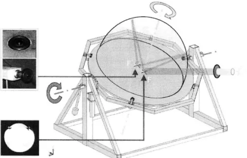
The goniophotometer application allows for the quick study of new window materials, providing broad coverage in both the spectrum and angular regions. The system uses a specially coated ellipsoidal surface to capture light, reflected or transmitted by the material sample situated at one of the ellipsoid's focal points, at a camera located at the other focal point (see Figure 2). The light for these studies must pass through a filter wheel that holds a series of filters, which divide the light into different wavebands to increase the Heliodome's ability to characterize the spectral properties of the sample.
More specifically, incident light passes through the filters of the filter wheel before reaching the sample, and so the camera at the second focal point only sees the reduced waveband of light. To fully characterize the sample over the entire visible and infrared spectrum, images must be taken of the reflection and transmission effects using each filter. The filter wheel's main function is therefore to quickly and accurately change the filter employed during each stage of testing.
While using the goniophotometer mode, users will be able to accurately measure and "[predict] their performance in terms of lighting and solar gains management
potential" (Andersen et al. 2007). These studies will enhance the heating and lighting properties of fenestration systems by controlling the entrance of visible and infrared light into a building.
The heliodon application can be used to see the effect of sunlight penetration or on a small-scale architecture model. By studying how sunlight can potentially fall on different rooms at different times of the day (or different days of the year), architects can reduce "potential glare risks, strong contrasts and predict probable overheating problems" (Andersen et al. 2007). Architecture students at MIT will benefit especially from the research available through this device.
2.2
Heliodome System Components
The main components of the Heliodome system are the rotating table, the NIR and CCD cameras, the user interface the filter wheel and the beam shaper. These
elements have been developed through independent projects, and each component has its role within the system. The control system will bring these elements together into one cohesive system that coordinates the use of these components to produce more accurate results more efficiently. Specifically, the control system will allow one user to operate these systems from a single location using one computer interface.
The wireless system will give the cameras the ability to communicate wirelessly with the user interface and transmit images and instructions between the two points. The filter wheel controls will automate the filter wheel assembly by rotating the wheel
according to user commands. Both systems will make the Heliodome system more efficient and more accessible to researchers and students.
2.3 Cameras
Figure 1: On the lett is the Kappa VX2U CCU Camera, lying next to the tish-eye lens, and on the right is the Sensors Unlimited NIR Camera with its power inverter.
There are two cameras for recording images in the Heliodome project. The Kappa DX20 CCD camera, shown on the left in figure 1, captures light in the visible range of frequencies, with an optical sensitivity of 280 nm to 1100 nm (Kappa 2003). This camera is essential for capturing both large scale images of the models and small images of concentrated beams for the goniophotometer mode. The camera can upload
images to a computer through a program provided by the manufacturer, and also through user developed programs by means of a C++ SDK provided by Kappa, Inc. Kess Eburu, an outside consultant, developed a Software Development Kit to use the camera through the visual basic interface (Eburu, 2006). The Kappa camera connects to a computer through an IEEE 1394 cable (Kappa 2003).
The Sensors Unlimited Near-Infrared camera, shown on the right in figure 1, has an optical sensitivity of 0.9 gm to 1.7 jm. It connects to a computer through a 45-pin digital connection that connects to a frame grabber on the computer. The NIR camera also has an analog BNC composite video output that can be used to display the camera output. The camera has multiple exposure settings that can be adjusted manually through a dial or electronically through the digital interface (Sensors 2004).
\•
>%-Figure 2: The Heliodome table, when used as a goniophotometer, has two focal points, one which transmits or reflects light and the one where the camera is placed to collect light dispersion data. (Andersen 2007)
When the table is used as a goniophotometer, the camera taking measurements is placed at one of the focal points located on the table. The camera has a mount under the table to secure it in this position. In order to detect incoming light reflected from any
point on the hemi-ellipsoid (180' opening), the camera is fitted with a Fujinon high resolution fisheye lens (Gayeski, 2007). Both the Sensors Unlimited NIR camera and the Kappa CCD camera can be used in this setup. The goniophotometer setup is shown in Figure 2, which illustrates the placement of the camera at a focal point to measure the
reflected rays of light. Attached to the bottom of the table is an L-shaped mount for securing the camera at that position.
The cameras also play an important role when the table is used as a heliodon. The camera is fixed above the table using an adjustable camera mount in this configuration. The heliodon mode does not require the use of the fisheye lens, but uses a conventional lens on the camera. For the heliodon mode, the table is equipped with an adjustable camera holder to secure a camera above the table. A camera placed above the table can
be found in a variety of locations and positions, but will always be fixed to the rotating platform. In either mode, the camera must be attached to a power source and a data transmission source in order to operate.
2.4 Command interface
Figure 3: The viewer window that will access and display the cameras' images to the Heliodome user (Osser 2007).
A visual basic interface was developed for the Heliodome project for controlling both the table and the cameras from a desktop computer (Osser 2007). One of the main goals of the interface is to provide video and photographic feedback of the daylighting conditions within a model, providing a basis for comparison and documentation in students' research. A picture of the interface's layout is shown above in figure 3, with the video feedback located in the lower left-hand box. The interface was designed to assist architecture students in designing spaces affected by daylight.
The interface was developed in Visual Basic. It communicates with the Kappa camera using a visual basic Software Development Kit that translates the SDK provided by Kappa and allows the interface to send commands to the camera. The SDK detects and controls Kappa cameras that are physically connected to the computer through a wire. The current interface finds the camera in a list of devices, opens and runs the camera on command, and closes the stream when it is no longer needed. The interface can also deal with exceptions such as not finding a device or losing the link to the camera.
The first interface window allows users to control the rotating table and cameras by entering in desired data points for scale model analysis. A second window allows users to collect and record visual feedback from a camera mounted on the table (Osser 2007). Camera modes include recording a continuous real-time image and taking a series of images either manually or automatically. The interface also contains the option of
-- -- -- -- -- -- - --- - --- -- - ---- ---- - -- -- --- -- - - --
--Sbi: Goto o
i :i: :::, :Irnaoevo"di~Y
- ---~---Li--- - --- --- :
Videýs::
SeI.Umhs~n llhnr YI~dD.Ya -use thi option t captre '
fj Y - I 1 M - I.. ( P-rtielDaTrawke, (choosetmesobel-4 :f" oe Image a., cho ~ice. per hour These ortthe Imagesday
;!FebruW *ýZX
From To p.d.g doa using the VW_
00 AM I AM *V.,.. b , Th, OPIl, 10
00 1,PM 9i0 ~o : M : :::r~d true -. liable. -- ýW a. .inot eY
r·k. Cap,.,. Vi -_ovie ... ~--~~~-~-~-Ga-e i : I : I i I : ::
saving the current image for storage. These functions are a crucial part of the interface, since they provide a means for analyzing the building designs and window materials processed by the Heliodome system.
2.5
Rotating Table
The Heliodome table provides a platform for achieving full angular analysis of potential window materials and building designs without utilizing a time-intensive scanning process (Andersen et al. 2007). The versatility of this device and its ability to provide a complete analysis of Daylighting effects make it a very valuable tool. The wireless system will add to the versatility of this tool, with the goal of interfering as little as possible with its capabilities.
The rotating table was developed by Dean Ljubicic in 2005 (Ljubicic 2005). The table possesses two DC motors to turn the table about two separate axes, giving it a wide range of motion that allows researchers to perform full angular analysis on research samples. The table can rotate 360' about its azimuth axis and 360' about its altitude axis. The table's freedom of motion in these two axes is a crucial element to performing complete analysis using both the goniophotometer and the heliodon modes.
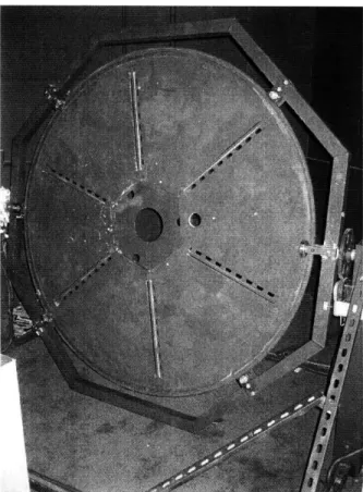
Figure 4: The Heliodome table consists of a rotating table to which a camera, ellipsoids, advanced fenestration materials and/or architectural models are secured to conduct studies.
The table has a unistrut skeleton of six spokes providing the shape and strength of the table, which can be seen in Figure 4. Aluminum plates provide the wide surface of
the table for mounting equipment and scale models (Ljubicic 2005). Major alterations to the table are undesired due to the complexity in dismantling and rebuilding the table, and the desire to use the table during the project.
The table is also designed with a large hexagonal hole in the center, which can be used to mount fenestration samples when using the table as a goniophotometer. The hexagonal hole cannot be obstructed by any object that would interfere with the transmission of light from the lab's HMI lamp (in any of the table's possible orientations).
2.6 System Interactions
The coordination of the movements of the table and the actions of the recording camera is one of the most vital parts of the Heliodome project. The cameras record images for a project at different stages, and the motors move the table between different stages in a quick and smooth motion. These actions should be coordinated by the
interface, and this property applies to both the goniophotometer function and the heliodon function of the Heliodome table.
The motors are controlled by the interface by a series of microcontrollers, which control their movement with shaft encoders. Communication between the computer and the microcontrollers is achieved through serial ports on the microcontroller board. To achieve coordination between the cameras and the motors, the interface must be able to read both the camera output and the encoder output from the motors and coordinate these devices.
The filter wheel's motion will eventually be part of the control system as well. Once automation of the filter wheel is complete, a simple microcontroller board can be developed to communicate with the computer using a serial port. The microcontroller will have the ability to turn the filter wheel motor on or off, and will also read a break-beam sensor to determine the wheel's position. Connecting this microcontroller board to the motors' board will allow these two devices to be used together.
3. Controls System
3.1 Wireless System
3.1.1 Requirements
The data and power transmission needs of the cameras are usually supplied through wires between the computer or a power outlet, and the cameras. However, because the cameras must be mounted on the moving table in order to be effective, use of cables would restrict the motion of the Heliodome table (Ljubicic 2005). A different solution was needed to meet the overall system requirements.
The wireless system must transmit images wirelessly to the user interface located on the desktop computer. It must also transmit images from both the Kappa CCD camera and the Sensors Unlimited NIR camera, taking into account the differences in acquiring these images. The video stream should allow users to make a rapid assessment of the experiment during its execution, so that additional tests can be run in the same session. The wireless connection application should also allow the user to change the camera's parameters, for both the SU NIR camera and the Kappa CCD camera, in order to optimize the images.
The goal of the project is to adding the capability for wireless control and data transmission to the system while preserving the versatility of the original table. The rotating table should retain its full range of motion, while the available angles for
inspection of materials in transmission mode should be minimally restricted.
3.1.2 Design and Selection
A variety of technical designs were considered to meet these requirements.
Possible designs included using a slip-ring to transmit the electronic data, using a hanging wire with a ball and socket connection to transmit the data, and achieving a wireless connection through a Bluetooth port or a router. However, a design centered around a laptop mounted on the table was selected as the most versatile and easily implemented option available.
While the choice of using a laptop comes with a high capital cost, it has several advantages over other approaches. The need to accommodate two separate camera devices as opposed to one was a large factor. Many other solutions, such as the slip-ring and the router, would have significantly different designs depending on which camera was being used; the laptop could be easily reconfigured through the operating system. The laptop was also more compatible with the cameras' existing cables, because other solutions would require devising a new wiring method for data transmission. Thus, using a laptop would reduce amount of development needed to implement the system, and reduce the uncertainty of using more experimental methods.
3.1.3 Laptop
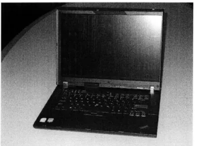
Figure 5: The Lenovo R61e ThinkPad has a durable case and an estimated battery life of four hours.
A design centered on a laptop was chosen primarily for its versatility in
addressing the needs of both cameras, which are integral components of the Heliodome system. The design was also chosen for its ability to integrate well into the current system, without requiring invasive modifications or restrictions on the capabilities of the system. This will greatly facilitate the transition to a fully wireless system.
The laptop will fit into the system with an addition to the camera assembly for power and some additional programming for connecting the camera to the interface across the wireless network. The laptop system can also changee to support changes in the interface and/or new hardware, and can support additional programs that add
functionality to the laptop, such as external software from the camera manufacturers that can be used remotely to take images. Other software could include file-transfer programs and user developed applications for controlling the cameras automatically.
A Lenovo ThinkPad R61e laptop, shown in figure 5, was selected for having a robust case, relatively cheap price, and capacity for hardware additions. The specific laptop model was chosen based on a few crucial requirements: a robust frame to protect against drops, a wireless card for connecting to the local wireless network, and a battery life of at least four hours. Two external additions completed the current system: an extra laptop battery and a PCMCIA card that provided three Firewire ports to the laptop.
3.1.4 Laptop Holder
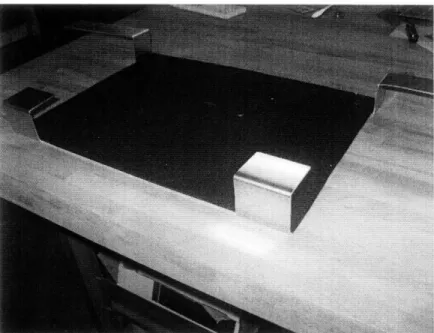
Figure 6: The bottom straps of the laptop holder secure the laptop using compressive force.
In order to keep the laptop in close proximity to the cameras, a retention structure was built to fit under the table. The holder secures the laptop underneath the table without significantly interfering with the transmission of light to the center, destabilizing the table, or altering the table's motion. The holder design also ensures that the laptop does not overheat, and that the laptop can connect with the cameras.
The first iteration of the laptop was constructed using steel L-bars cut to size and connected using 5/16" aluminum screws. This design relied on the L-bars to provide structure and the screws to supply the strength to hold the holder and the laptop together. While this design choice allowed for quick assembly of the holder, the strength of the screws, the fit of the holder to the laptop, and the risk of scratching the laptop were not ideal. This first attempt did not meet the initial design specifications and was discarded.
The second laptop holder was built primarily from a single piece of 1/16" 6061 aluminum sheet metal. The decision was made to use a thin piece of aluminum rather than a less-malleable thicker plate; a thick plate would be stronger but would also weight
more and be much harder to bend and shape around the laptop. This component is show in figure 6. A 12"x 24" sheet of 1/16" aluminum was riveted to the top of this
component, completing the holder. Both sheets of aluminum weigh less than the materials of the previous iteration.
The end of the holder has two U-shaped pieces of metal that fit around the end of the laptop and hold it securely in place. The metal was originally designed to simply fit over and constrain the laptop, but it was built in a way that the metal actually presses against the laptop to maintain it secure. The elastic behavior of the sheet metal bends the shape to fit around the laptop, and the resulting tension in the metal creates a compression force on the laptop. To add an extra layer of protection, the laptop is held in place using
a Velcro strap lying across the face of the laptop, constraining the laptop on all six faces. Testing has shown that the laptop remains securely in place without rattling or moving.
The laptop is an important piece of equipment, and must be protected from scratching and denting. To protect the laptop from wear against the hard metal surface, the holding surface that was in greatest contact with the laptop was covered with a sheet of felt using adhesive. The felt will provide less resistant against the laptop sliding in and out, and serves as a protective barrier for the laptop case. Also, the holder provides plenty of open area for cooling, to prevent the laptop from overheating; the laptop is only constrained at a few key positions, relying on the rigidity of the laptop case to keep it properly constrained.
3.1.5 Counterweights
rigure /: I wo steei Deams are screwea to tne bottom ot the table and act as appropriate counterweights stabilizing the motion of the table.
The laptop and the holder weigh a combined 3.9 kg, enough to alter the dynamics of the table. When the table is tilted, the weight of the components also exerts a torque on the azimuth motor due to gravity. It is essential to properly counterbalance the presence of this mass to ensure the table moves evenly in all configurations without stalling the motors or straining them beyond their limits.
For counterweights, two 1018-steel beams weighting 1.9 kg each, with
dimensions of 12"x2.5"x0.5" were selected. Long slender beams were selected, rather than compact masses, because they matched the geometry of the table's skeleton, and they provided the least obstruction to light from a lamp shined on the table. The beams are fixed to the table using 5/16" aluminum screws, which fit the existing honeycomb pattern in the aluminum skeleton. This arrangement is shown in figure 7.
One possible addition would be to replace the steel beams with lighter aluminum beams in cases when the laptop is not in the holder. The aluminum beams would provide
enough weight to counterbalance the holder itself. However, the laptop is expected to be in the holder the majority of the time, which would reduce the need for alternate
counterweights.
3.1.6
Wireless Image Transmission
In the full system, for a camera to communicate with the user interface, the system must be able to transmit the images from the laptop that is reading the camera stream to the stationary desktop computer that will display the images. Several techniques were used to try to move these images, including use of shared folders, WMI protocols, and FTP-based applications, but they were ultimately discarded due to limitations and difficulties in their implementation.
Using WMI communication, the program achieved some basic communication between the computers, but was only adequate for transmitting system information and not stored files or data streams. FTP-based methods required the use of free software to set up an FTP server, and were limited to static file transmission only. The use of a shared network folder between the two computers was also considered but not pursued, since the preferred method would involve controlling the cameras as well.
Facing difficulties due to time constraints with the transmission of a real-time camera image, the decision was made to obtain help from a programming consultant. Kess Eburu, a software consultant who worked on the Heliodome project before, was brought in to develop the software necessary for data transmission.
Kess Eburu developed a client-server system that uses .NET Remoting, a programming framework for Visual Basic .NET programs. .NET Remoting allows programmers to write applications distributed over several platforms by maintaining separate copies of system elements (objects) on the different platforms (Rammer and Szpuszta 2005).
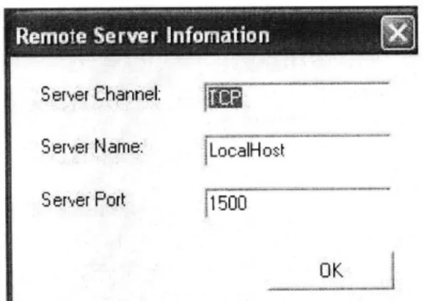
S er,,er Channel:
Seref Namre: LocalH ost
Serer Port 5
Figure 8: The server and client applications communicate through the same port, which can be configured by the user.
The new application relies on two components: a server application that runs on the laptop and a client application that runs on the stationary desktop. The server
runs the camera and reads the camera output, and listens to an open TCP port on the laptop. The port configurations are set by the user, as seen in Figure 8. The client program accesses the same port through the network to gain access to the laptop files, and copies the image object to the desktop computer, where it is displayed on the user's screen.
Figure 9: The Client application of the server-client software displays the images transmitted from the laptop. This can be adapted for use in the command interface.
A new image is requested by the client application (through the network) every 0.1 seconds, resulting in a real time display on the user's computer. This image can also be stored on the computer for research and analysis purposes. Because the client
application can be configured to access any computer the server is running on, the software can be used between any two computers connected over a network.
The camera usually communicates with a computer using an IEEE 1394 6-pin cable, which can transmit data at speeds of 400 Mbits/s4. The limiting factor of the
wireless transmission speed in the new system is the wireless network speed. The wireless network is an 802.1 la/b/g network, whose speed on the computer is measured at 54Mbits/s. Using the network, there is a delay of about Is between images, which was deemed acceptable. The software timer acquires a new image every 0.1 s.
The image transmitted through the client-server software is stored as an image in a picture box class (in visual basic). The code can easily be adapted to work with the command interface, by simply copying the code into the interface's project. The stand-alone application can be used for testing and simple image acquisition.
Afterwards, the system was further optimized in lab to meet other desired specifications. A button was added to the client application to save images for future reference. The server application was modified to begin reading from the camera as soon as the application is started, setting up a port internally without input from the user. The ability to open or close the connection to the server was also added to the client application. The final goal is to simply turn on the laptop, have the server application run automatically, and then plug in the camera when the user is ready, while giving the user as much versatility as possible on the client side of the application.
3.2
Filter Wheel Controls
Current goniophotometers are limited in their ability to provide a complete description of the transmitted or reflected luminance (or irradiance) caused by a fenestration sample (Gayeski and Andersen, 2007). One limitation is that many
goniophotometers cannot characterize how specific portions of the light spectrum behave, and merely take measurements over the whole spectrum. To provide an accurate
measurement of the spectral variance of the sample without compromising the
measurement of the spectra's luminance or radiance, a series of filters divides the visible and infrared spectrum into wavebands for goniophotometer measurements. This will allow for measurement of the radiance and luminance over varying wavebands, providing
a more complete picture of the properties of the fenestration sample.
A filter wheel was designed by Tim Koch to hold and cycle through the filters used with the goniophotometer (Koch 2007). The device is a pair of LDPE wheels on which the filters are mounted; rotating the wheel changes the filter that the system uses. It is desired to operate the filter wheel autonomously, allowing a user to control the
system from a user interface. The addition of motors to the system would enable the filter wheel system to be controlled remotely. The motor would be connected to a drive gear that would spin the wheel, and would also be connected to a controller that would regulate the speed and position of the motors. This project addressed the selection and installation of the filter wheel motors.
3.2.1 Motor Selection
The motor needed enough torque to drive the combined mass of the filter wheel and the filters mounted on it. The filter wheel needed to switch filters at a rate of 1 filter every two seconds, including idle time when the wheel was not moving but the drive gear was.
Each filter wheel rotates about its central axis on a steel rod mounted on a pair of plastic bearings. Each filter weighs about 1.2 kg; 10 filters around mounted on the wheel at one time. Using a safety factor of 2, a motor needs to supply about 0.57 W of power to spin the wheel at 3 rpm, including a torque of 16 mN-m. The motor must also be small enough to fit in the filter wheel assembly. The final output must have relatively low
speeds and relatively high torques, due to the weight of the wheel and the constraint on speed due to the function of the filter wheel.
The final motor selection was a 25RPM 12VDC Parallel Shaft Gearmotor from Merkle-Korff Industries. The motor can provide a full load torque of 2260 mN-m, more than enough to turn the wheel from rest. The speed of 25RPM at 12VDC is more than enough to turn the filter wheel at 3 rpm.
The motor is equipped with a 45:1 gearbox in order to achieve the lower output speed and higher output torque desired. The gearbox allows the motor to fit the
specifications without needing external gearing, but also make it more difficult to fit in within the filter wheel system. The motor and gearbox will not be strained within their maximum capabilities, and should last for the lifetime of the Heliodome system. The
selected motor meets the specifications of the system and worked after installation.
3.2.2 Motor Installation
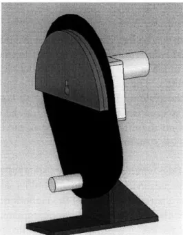
Figure 10: The drive gear assembly for the filter wheel.
The filter wheel and driving gears were designed by Tim Koch. The motors needed to be integrated into the existing system as elements of the driving gears, and the entire assembly needed to be integrated to the existing filter wheel system. A solid model image of the assembly is show in figure 10. The motor is connected to the drive gear in order to move the filter wheel. The drive gear consists of a LDPE plate fitted to a Delrin rod. Upon rotation, the Delrin rod enters slots on the filter wheel and rotates the wheel. When the rod is not pushing the wheel, a curved slot mounted on the drive gear engages the filter wheel, holding it in place to prevent drifting.
The motor had a small shaft for transmitting torque to the gear assembly; it was decided to protect the motor and enhance the fit of the motor with the gear by designing a
piece that would connect the shaft with the larger drive gear. A fitting was manufactured from 1/•" thick 6061-aluminum using a water jet cutter. The fitting was cut to the shape of the shaft on its interior, and into a hexagon along its exterior. The hexagonal shape was cut into the gear at its rotational axis; the hexagonal shape would decrease the possibility of cutting into the drive gear material while preventing the drive gear from slipping along the shaft. To prevent the fitting from slipping along the shaft, a 5/16" set screw was installed in the fitting to press against the shaft. As the gear should not receive any significant horizontal force during use, the assembly should be sufficient to hold the pieces in place. The complete assembly was screwed into place next to the filter wheel so it could be used.
4. Discussion
The wireless system design was chosen for its versatility but contains a number of limitations. The power sources for the cameras are external batteries, giving the system a limited operating time before recharging is needed. The estimated operating time of the system is about four to six hours, due to the battery capacity of the external battery and the laptop battery.
The wireless network can be used to transmit images, but it is an imperfect substitute for the faster wired connection. The speed of data transmission over the
802.1 la/b/g network found in lab is 54 Mbit/s, while the data transmission rate through
the Firewire cable is 400 Mbit/s. The rate will not affect the quality of the image, but did affect the response time of the system. There is a noticeable lag of Is between a motion
and its resulting image on camera. Because of the focus on data at different set points in the apparatus, the delay will not significantly hinder use of the Heliodome system, though it will slow down the use of the system.
The infrastructure of the wireless system has a small effect on the operation of the goniophotometer mode. The presence of a laptop and holder system underneath the rotating table will reduce the operational scope of the Heliodome by blocking a possible
path for light transmission to the sample in the goniophotometer mode. To reduce the blocking effect of the new structure, the laptop holder was installed on the table behind the camera mount, which was already blocking this path.
The laptop system has a disadvantage of needed the laptop to be powered on for use. With remote desktop software, the laptop can be used without removing it from the Heliodome apparatus. However, to turn on the machine, the laptop must be removed from the holder to access the power button. Its removal would temporarily unbalance the weighting system of the table; anticipation of this effect would be important. A solution to this problem would remove the inefficiency in starting the system.
An additional laptop battery was purchased to extend the battery life of the laptop. It can fit into the optical slot typically reserved for the DVD reader; it would not add any additional weight or volume to the system. The extra battery will help meet the system
requirement that the laptop system be available through the course of an entire days use, estimated at about six to eight hours.
The programming of the communication interface was the most difficult portion of the thesis. Several attempts were made to produce a viable solution, some of which reduced the ability of the interface to function. However, the interaction between two
different operating systems and the underlying network created many unforeseen problems that prevented different approaches from being effective. The programming component also interacted with the DXInterface DLL file, which was not easily
accessible or changed.
5.
Conclusion
5.1 Achievements
There were a number of achievements in this thesis. One primary achievement was developing and executing a wirelessly based system, with the Kappa camera and the Lenovo laptop, to transmit images from the rotating table to the stationary desktop computer. The system achieves data transmission without interfering with the motion of the table, and with only a small amount of blockage of the transmission of light to materials held in the center of the table. The design meets all of the necessary
specifications to maintain the functionality of the Heliodome system, while enhancing its capabilities. An appropriate laptop was selected, a simple and light-weight holder was designed and manufactured, and different programming (and computer) pieces were acquired or developed to build a solid foundation for a wireless system.
The second achievement of this project was to select and install motors for the Heliodome system, with the long term goal of completely automating their motion. At present, the motors are run using power supplies, but their presence ensures an efficient transition between filters and greater accuracy in the positioning of the filters.
The Heliodome system is in a great position to move forward, using automated controls to bring the entire system together and make its use by students much easier.
5.2 Future Steps
There are many additions that need to be made to the current system. The NIR camera is not fully integrated into the system, and needs to be a functional part of the Heliodome system. A board is needed for the laptop in order to plug the NIR camera into the system, and an L-beam holder is needed to hold the NIR camera at the focal point. However, the system is in place to accept these elements without any major to the current system.
The Kappa camera transmits data through an IEEE 1394 6-pin Firewire cable, which usually provides power to the device as well. Unfortunately, this power is not
available through the PCMIA Card. As a solution, a Li-Ion battery for a power system, developed for the NIR camera by Keith Molina, can be modified with an alternate plug to provide power through the Firewire port. This will ensure that the wireless aspect of the system is not compromised.
NIR Camera integration includes setting up architecture to transmit pictures between the laptop and the desktop computer. This could include reading the NIR camera's images in a visual basic application, and then using the same program the CCD camera uses. The NIR Camera software can be loaded onto the laptop, and used
remotely as a temporary solution.
The laptop needs a frame grabber to communicate with the Sensors Unlimited NIR camera; one needs to be installed internally or externally from the camera. Using the frame grabber, the camera will be able to control camera parameters and receive infrared images. The integration of the SU NIR Camera will provide important analysis to the infrared spectrum of light, expanding the Heliodome's versatility.
It was discovered that the laptop's CardBus drive will not provide enough power to the Kappa CCD camera. An external battery purchased for use in the portable power system, developed by Keith Molina, can be adapted to power the CardBus using a pin connector. This attachment can be attached to the external battery and its completion will allow the wireless system to operate autonomously from any source outside the
Heliodome table.
Currently, the visual basic application can read the camera images, but cannot adjust any of the camera parameters. Adding this application will be crucial to the system's growth and viability. The initial direction of the project was to address all the cameras' functions over the wireless network, but after several attempts resulted in
multiple error messages with no apparent solution, a backup solution was enacted due to time constraints. Revisiting this issue to restore the full functionality of the camera will
be important to the project.
The current camera system uses the DXInterface SDK, developed by Kess Eburu, to read and send commands to the Kappa camera. For further development, it may be modified to use a different set of commands to transmit images from the Sensors
Unlimited NIR Camera. This would require developing functions for both acquiring the images and modifying the camera parameters, since Sensors Unlimited does not provide a Software Development Kit for the camera.
The controls for the filter wheel will be integrated into the controls for the rotating table of the Heliodome system. Using microcontrollers and break-beam sensors, the filter wheel will be able to change filters based on computer commands from a user. This will include cycling through the entire wheel, adjusting the position of the wheel by one filter, and returning the wheel to a 'home' position. Communication between the motor and the computer will be achieved through serial ports on a microcontroller board.
5.3
Related Applications
The new wireless system may have many applications outside of the Heliodome system. One primary application it could be used for would be the field of robotics, for use in autonomous units that need to return data to a centralized location. Securing the necessary processor unit and providing for data transmission of sensors are two important elements in remote robots. While our particular approach is limited by the need for a wireless network, its use in urban or residential robots could be a valuable contribution.
Another related application would be to use the wireless system with security cameras. Security cameras are often located in remote places inaccessible by traditional wiring. This system is designed to take images from a normally inaccessible camera and provide its images in real-time for a substantial period of time. This is very similar to the needs of security cameras and may have a lot of potential uses in this field.
6. Bibliography
M. Andersen, N. Gayeski, E. Stokes, R. Osser, C. Browne, "The Heliodome project: an innovative approach in assessing solar-optical properties of light-redirecting materials in combination with sun course simulations", In Proceedings CISBAT 2007: Renewables in
a changing climate -Innovation in the Built Environment, Lausanne, September 4-5, 2007.
http://web.mit.edu/daylighting/publications/Andersen07_Heliodome_CISBAT2007.pdf M. Andersen. http://web.mit.edu/daylighting. 2007
Building Technologies Program, Office of Energy Efficiency and Renewable Energy (EERE), Department of Energy. 2007 Buildings Energy Databook. Washington: GPO, 2007.
D. Ljubicic, "Automated Support for Experimental Approaches in Daylighting
Performances Assessment", S. B. thesis, Mechanical Engineering, MIT, October 2005. K. Eburu (ScenarioSoft Inc.), "DXInterface .NET Adapter For Kappa SDK DX
2/DX 20 Manual Version 1.0", Technical Report, 2006.
Energy Information Administration (EIA), Department of Energy. Annual Energy Review 2006. Report No. DOE/EIA-0384(2006). Washington: GPO, 2007. http://www.eia.doe.gov/emeu/aer/pdf/pages/sec l_5.pdf
Fisk, William J.. "Health and Productivity Gains from Better Indoor Environments and Their Relationship with Building Energy Efficiency." Annu. Rev. Energy Environ. 200. Berkeley: 2000.
https://www.usgbc.org/Docs/Resources/Fisk%28LBNL%29HealthandProductivityEE200 0.pdf
N. Gayeski, New Methods for Measuring Spectral, Bi-directional Transmission and Reflection using Digital Cameras, S.M. thesis in Building Technology, Department of Architecture, MIT, June 2007.
N. Gayeski, M. Andersen, New Methods for Assessing Spectral, Bi-directional Transmission and Reflection by Complex Fenestration Systems, In Proceedings of SOLAR 2007: Sustainable Energy Puts America to Work, Cleveland, July 7-12, 2007. Kappa. "KAPPA ImageBase DX20 DX2." KAPPA Opto-electronics GmbH. 2003. T. Koch, Device for Selecting Lightwave Ranges via Computer Control for Studying Building Material Properties, S. B. thesis, Mechanical Engineering, MIT, June 2007 N. Stauffer, "Daylight device lightens electricity cost", TechTalk-Serving the MIT community, Vol. 51, No. 26, pp. 4 & 7, May 9, 2007.
http://web.mit.edu/newsoffice/2007/energy-daylight-0509.html
R. Osser, M. Andersen, L. Norford, "Development of Two Heliodon Systems and Recommendations for their Use", In Proceedings of SOLAR 2007: Sustainable Energy Puts America to Work, Cleveland, July 7-12, 2007.
Rammer, Ingo and Szpuszta, Mario. Advanced .NET Remoting, Second Edition. Berkeley: Apress, 2005.
http://library.books24x7.com.libproxy.mit.edu/book/id_9816/viewer.asp?bookid=9816& chunkid=0304364867#56
Sensors Unlimited, Inc. "High Speed SU320-1.7RT 120FPS Indium Gallium Arsenide Area Camera Operation Manual." Doc. No. 1013216 Rev. C. Princeton: Sensors Unlimited, Inc. 2004.