HAL Id: hal-01403867
https://hal.archives-ouvertes.fr/hal-01403867
Submitted on 28 Nov 2016HAL is a multi-disciplinary open access archive for the deposit and dissemination of sci-entific research documents, whether they are pub-lished or not. The documents may come from teaching and research institutions in France or abroad, or from public or private research centers.
L’archive ouverte pluridisciplinaire HAL, est destinée au dépôt et à la diffusion de documents scientifiques de niveau recherche, publiés ou non, émanant des établissements d’enseignement et de recherche français ou étrangers, des laboratoires publics ou privés.
5-ALA Photodynamic Therapy in Neurosurgery,
Towards the Design of a Treatment Planning System: A
Proof of Concept
Dupont C., N. Betrouni, S. Mordon, N. Reyns, M. Vermandel
To cite this version:
Dupont C., N. Betrouni, S. Mordon, N. Reyns, M. Vermandel. 5-ALA Photodynamic Therapy in Neurosurgery, Towards the Design of a Treatment Planning System: A Proof of Concept. Innovation and Research in BioMedical engineering, Elsevier Masson, 2016, �10.1016/j.irbm.2016.11.002�. �hal-01403867�
1
5-ALA photodynamic therapy in neurosurgery, towards the
design of a treatment planning system: A proof of concept
C. Dupont, PhD student, N. Betrouni, PhD, S.R. Mordon, PhD, N. Reyns, MD, PhD, M. Vermandel, PhD*
Univ. Lille, Inserm, CHU Lille, U1189 - ONCO-THAI - Image Assisted Laser Therapy for Oncology, F-59000 Lille, France
*Corresponding author: m-vermandel@chru-lille.fr
Abstract
Purpose Glioblastoma (GBM) treatment still remains a complex challenge. Among
alternatives or adjuvant therapies, photodynamic therapy (5-ALA PDT) appears to be a promising approach. 5-ALA PDT can be delivered intraoperatively, early after tumour resection, or interstitially according to brain tumour location. A treatment planning system was designed to manage dosimetry issues before PDT delivery.
Methods The TPS was developed according to a specific workflow from stereotactic
image registration to light fluence rate modelling. Here, we describe a proof of concept of a treatment planning system (TPS) dedicated to interstitial 5-ALA PDT. This tool enables the planning of a whole treatment in surgical stereotactic conditions. Stereotactic registration and dosimetry components are detailed and evaluated. The registration process is compared to a commercial solution (Leksell Gamma Plan®, Elekta®, Sweden) defined as the ground truth and dosimetry model implemented in our TPS and is compared to numerical simulations.
Results Registration achieved a sub-millimetric mean relative error that matched the
standard MRI resolution. Dosimetry comparison showed a negligible error between analytical and numerical models and enabled a validation of the dosimetry algorithm implemented.
Conclusions A treatment planning system was designed to achieve 5-ALA PDT
simulations before the patients underwent surgery. Similarly, for radiation therapy, we proposed a system to plan and evaluate the 5-ALA PDT dosimetry for optimizing treatment delivery. Although this system remains to be perfected, this preliminary work aimed to demonstrate the feasibility of planning 5-ALA PDT treatments in stereotactic conditions. Future improvements will mainly focus on the optimization of the treatment delivery, automatic segmentation and GPU-accelerated Monte-Carlo management to take into account GBM tissue heterogeneity.
Keywords: 5-Aminolevulinic Acid, 5-ALA Photodynamic Therapy, Glioblastoma, Dosimetry, Simulation, Treatment Planning System
2 I. Introduction
Glioblastoma (GBM) is the most common malignant primary brain tumour. It represents the third leading cause of death by cancer for young-aged people (aged between 15 to 34 years), and 5 to 7 new cases per 100000 inhabitants are recorded each year [1]. GBM is known for its poor prognosis; a median overall survival of 14.5 months is reported [2]. The standard of care has been described by the European Organization for Research and Treatment of Cancer (EORTC) and the European Society for Medical Oncology (ESMO) [3]. When achievable with limited neurological impairments, patients undergo surgery for maximal GBM cytoreduction. The extent of resection (EOR) significantly impacts the overall survival. Debulking at least 98% of the contrast enhancement leads to an increase in median survival of 4 months [4, 5]. Radiotherapy and concomitant adjuvant chemotherapy are delivered to delay tumour relapse.
5-Aminolevulinic-acid photodynamic therapy (5-ALA PDT) appears as an interesting approach to complement GBM treatment [6-9]. Basically, 5-ALA PDT is a focal and selective treatment that relies on the combination of three factors: photosensitizer (PS), oxygen and light. In particular, 5-ALA is used as a precursor drug treatment for GBM PDT; it is a natural prodrug that becomes protoporphyrin IX (PpIX), which is the photosensitizer [10]. An exogenous supply of 5-ALA leads to a PpIX-specific accumulation in the neoplastic cells. Then, light exposure triggers the reaction between the PS and oxygen in order to produce cytotoxic molecules (singlet oxygen and free radicals). Direct and indirect effects on tumour cells contribute to the tumour treatment.
When tumour resection is achievable, 5-ALA PDT is delivered during the course of surgery, early after fluorescence-guided resection (FGR) [11]. FGR is also based on the tumour specific PpIX accumulation, which induces a selective fluorescence spectrum after a specific wavelength of light exposure. PpIX is a photoactive compound that absorbs blue light (375-440 nm) and then emits red light in the visible spectrum, mainly at 635 nm. A correlation exists between higher cellular PpIX concentrations and greater fluorescence intensities [12, 13]. However, even when EOR is complete from a radiological point of view, the tumour cells still remain in the surgical cavity borders. Thus, the main goal of intraoperative 5-ALA PDT is to benefit from FGR, for which 5-ALA would already have been administered, to provide light exposure at a higher fluence rate. The PpIX absorption peak at 635 nm (red) is preferentially applied to achieve the deepest light exposure possible.
For some cases, interstitial 5-ALA PDT may be preferred. Optical fibres are inserted directly into the tumour target to illuminate the malignant tissues. Simulation of light propagation in brain tissues is required to plan the location of the light sources and to thus optimize the treatment in maximizing the volume of illuminated tissues.
For both modalities, intraoperative or interstitial 5-ALA PDT, a treatment planning system (TPS) is highly expected to plan such a surgery and compute the light exposure duration.
3
In this paper, we describe a first implementation of TPS in the context of interstitial 5-ALA PDT. This software includes stereotactic registration of DICOM images, manual delineation of the tumour target, light source insertion and dosimetry modelling.
II. Materials and methods
1. A TPS dedicated to interstitial 5-ALA PDT
The goal of this study was to demonstrate the possibility of planning interstitial 5-ALA PDT for GBM treatment under stereotactic conditions. The software was implemented with the integrated development environment C++ Builder XE8 (Embarcadero, Austin, TX,
USA) and the environment ArtiMED (URL:
http://www.onco-thai.fr/index.php?option=com_content&view=article&id=6&Itemid=140&lang=en)
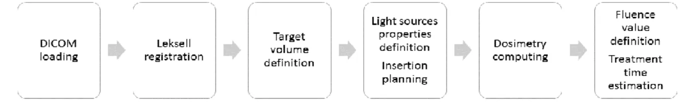
developed at the ONCO-THAI Lab. This tool, named iPDT-Plan, provides a user-interface composed of four main tabs corresponding to the typical workflow to perform a complete planning (see Fig. 1).
Fig. 1: Workflow of the iPDT-Plan TPS. Leksell registration and dosimetry computing phases are highlighted in this paper.
a. Stereotactic registration
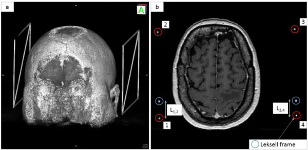
The first part of the iPDT-Plan is dedicated to DICOM viewing and stereotactic localization. The Leksell frame (Elekta®, Stockholm, Sweden) was preferred because of its common use in stereotactic neurosurgical procedures (Biopsies, Stereo-Electro-Encephalograms, Deep Brain Stimulation, Gamma-knife radiosurgery) [14-17]. Once the frame is setup on the patient’s head, it allows localizing a target point in the 3D Leksell space from imaging. Translation from computed tomography (CT) or magnetic resonance imaging (MRI) space to the Leksell space is achieved through an MR- or CT-indicator box clipped onto the frame during the exams. Radio-opaque rods representing the characteristic “N” of the Leksell frame were included inside at least two sides of the box. Thus, these six rods appear as points in the axial plane of the patient imagery (see Fig. 2). To perform a Leksell localization of the DICOM set, six points have to be located on all images. Two collections of points in R3 were created: the first P
IMA represents all four points on n slices in the imaging
modality (i.e., CT or MRI) coordinates, and the second PLeksell represents the theoretical
positions of the same four points in the Leksell frame coordinates. The main objective is to determine a matrix A allowing the conversion of PIMA in PLeksell such as that described in
Annex 1.
4
Fig. 2: a) 3D rendering showing the Leksell frame to the left and right side of the patient’s head. b) MRI exams showing the six dots (enclosed in circles) matching the 6 radio-opaque rods included inside the Leksell frame.
b. Light sources simulation
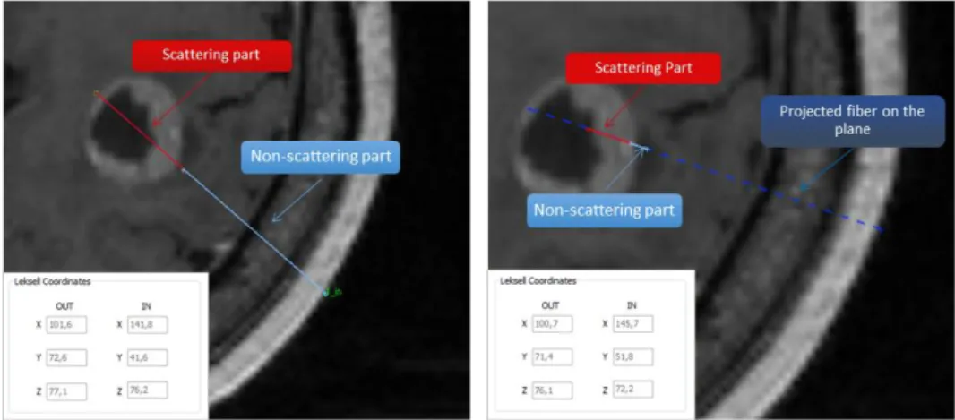
Once a target is manually delineated, the surgeon or medical physicist is able to simulate different treatment configurations through the placement of light sources inside the target volume. The light exposure for interstitial 5-ALA PDT treatment mainly relies on cylindrical optical fibres. These diffusers illuminate isotropically around the diffuser tip; between 10 to 50 mm lengths of cylindrical diffuser tip were implemented in the TPS. To simulate the insertion of optical fibres, the diffuser length (mm), the power of the source (mW/cm), and the input and output points (i.e., entry point into the skull and ending point in the brain) must be defined. Regarding the fibre position within the volume, two representations can occur (see Fig. 3). In cases where the whole fibre is contained in only one axial image, the fibre will be represented by two distinct parts: the scattering part, symbolized by a red continuous segment, and the non-scattering part, symbolized by a cyan continuous segment. In the case where the fibre is contained in more than one axial image, the fibre is represented in three different parts: the scattering part, represented by a red continuous segment, the non-scattering part, contained in the plane visualized and represented by a continuous segment cyan, and the projection on the axial image of the non-scattering part symbolized by a discontinuous segment navy blue (see Fig. 3). This distinction between those two non-scattering parts is used for visualization purposes in order to avoid crossing the vascular tree of the patient's brain. Thus, it is possible to visualize the progression of the fibre inside the patient's brain. Entry and ending points are directly converted into 3D Leksell
5
frame coordinates for using the stereotactic Leksell System (Elekta, Stockholm, Sweden) or for programming the insertion of optical fibres on a neurosurgical robot.
Fig. 3: On the left, the 20 mm diffuser fibre is contained in only one axial image, and the fibre is represented by two distinct parts: the diffuser tip (red continuous segment) and optical fibre part (cyan continuous segment). On the right, the 20 mm diffuser fibre is contained in more than one axial image. Three different parts appear: the scattering part (red continuous segment), the non-scattering part contained in the visualized plane (cyan continuous segment) and the projection on the axial image of the non-scattering part (navy blue discontinuous segment).
c. Dosimetry modelling
For a given treatment configuration (number, type and location of the light diffusers, power of the LASER light device) dosimetry modelling and lighting duration estimation are computed to provide an irradiance matrix (W/cm²) superimposed on the DICOM set. At each point of the space, irradiance values are computed with the analytical equation (7) [18-20]: ϕ(𝑑) = 𝑃. √2. 𝛿 𝜋. 𝑑. 𝑒−𝑑⁄𝛿 2𝜋. 𝜇𝑎. 𝛿² (2) With: Φ: irradiance (W/cm²)
δ: optical penetration depth = √3.μ 1
a.(μa+μs′) (dimensionless)
µs’: reduced scattering coefficient (cm-1) µa: absorption coefficient (cm-1)
6 P: power of the source (W)
This irradiance estimation is computed on each voxel of the volume. The coefficients used are provided from a previous study of Beck et al. in 2007 [7] and confirmed by a more recent study of Tedford et al. in 2015 [21]. They correspond to a normal brain tissue infiltrated by GBM tumour cells: µa = 0.2 cm-1 and µs’ = 20 cm-1.
Using the irradiance matrix, a light duration is estimated to deposit a fluence value (J/cm²) on a target pre-determined by the user. The larger the target, the longer the light duration to obtain a PDT effect on the treated volume.
2. Evaluation
a. Leksell frame registration
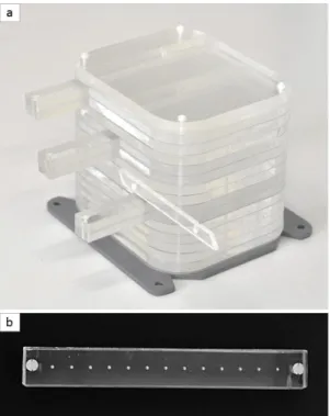
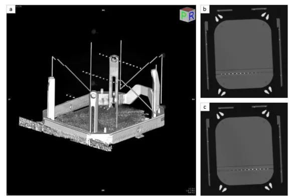
A phantom model was developed in our laboratory in order to evaluate the Leksell registration included in our TPS. A 15 cm3 cube of polymethyl methacrylate (PMMA) was designed with three rods (see Fig. 4). Thirteen radio-opaque marbles spaced 10 mm apart were inserted into these three rods.
Fig. 4: a) A phantom model designed to simulate the head of the patient was fixed on a Leksell frame. b) PMMA rod with 13 radio-opaque marbles spaced 10 mm apart.
This phantom was then fixed to a Leksell frame and imaged by CT (see Fig. 5). The coordinates of each marble in the Leksell frame were computed by both our TPS and the Leksell GammaPlan® (Elekta, Stockholm, Sweden) defined as ground truth. The metric to evaluate our Leksell registration was the distance d between Leksell coordinates of the same marble obtained by our TPS and the GammaPlan:
7
𝑑 = √(𝑥𝑇𝑃𝑆− 𝑥𝐺𝑎𝑚𝑚𝑎𝑃𝑙𝑎𝑛)² + (𝑦𝑇𝑃𝑆− 𝑦𝐺𝑎𝑚𝑚𝑎𝑃𝑙𝑎𝑛)² + (𝑧𝑇𝑃𝑆− 𝑧𝐺𝑎𝑚𝑚𝑎𝑃𝑙𝑎𝑛)² (3)
Fig. 5: a) 3D reconstruction of the CT phantom where the 39 radio-opaque marbles appear inside the Leksell frame. b) and c) CT slices of the phantom with 13 radio-opaque marbles appear in high-level contrast.
b. Dosimetry
To validate our dosimetry model, the partial differential equation named the Helmholtz equation (4) was defined as the ground truth [18, 22]. Under homogeneous conditions, this propagation equation provides an accurate estimation of irradiance values in the case where the mesh created to discretize the space is fine enough.
∇. (− 1 3(µa+ µs′) . ∇ϕ) + µaϕ = µ𝑠′. 𝑃 2𝜋. 𝑟. ℎ. 𝑒−(μ𝑎+μ𝑠 ′).(√𝑥2+𝑦2−𝑟) (4) with ∇ = [∂x∂ ,∂y∂ ,∂z∂] Φ: irradiance (W/cm²)
µs’: reduced scattering coefficient (cm-1) µa: absorption coefficient (cm-1)
P: power of the source (W) r: radius of the optical fibre (cm) h: length of the diffusing part (cm)
This model was implemented into the numerical modelling software COMSOL MultiPhysics 5.2, allowing a reliable and fast computation of the Helmholtz equation. A
8
homogeneous slab with identical optical properties to the analytical modelling used in the TPS was created. A cylinder was placed inside the cube and defined as the source.
The metric (5) used to evaluate the analytical model implemented in the TPS was the difference of the irradiance Irr value obtained by both analytical and numerical models at the same distance d from the light source:
𝑟𝑒𝑙𝑎𝑡𝑖𝑣𝑒 𝑒𝑟𝑟𝑜𝑟 (%) = 𝐼𝑟𝑟𝑛𝑢𝑚𝑒𝑟𝑖𝑐𝑎𝑙(𝑑) − 𝐼𝑟𝑟𝑎𝑛𝑎𝑙𝑦𝑡𝑖𝑐𝑎𝑙(𝑑)
𝐼𝑟𝑟𝑛𝑢𝑚𝑒𝑟𝑖𝑐𝑎𝑙(𝑑) (5)
3. Materials
The phantom was imaged with a Siemens CT scanner (Erlangen, Germany) with a 512x512 pixels image dimension and a resolution of 1 mm. DICOM patients used in this study were acquired with a Philips (Amsterdam, Netherlands) MRI T1 3D FFE with a slice thickness of 1 mm and a 256x256 pixel dimension. Patient images were realized as part of their treatment protocol of radiosurgery.
III. Results
1. Leksell registration evaluation
Distances (mm) were computed for each marble inserted in the phantom model (see table 1). The mean distance computed was 0.8 ± 0.3 mm (maximum = 1.3 mm).
Markers 1 2 3 4 5 6 7 8 9 10 11 12 13
Rod 1 1.0 0.3 0.2 0.6 0.7 0.7 0.9 1.4 0.5 0.7 1.1 0.6 0.5 Rod 2 1.8 1.2 1.3 1.3 1.5 1.1 0.6 0.7 0.8 1.2 0.9 1.3 1.1 Rod 3 0.5 0.4 0.8 1.0 0.9 0.7 0.7 0.9 0.5 0.5 0.6 0.8 0.7
Table 1: Distances (mm) between Leksell coordinates of the radio-opaque marbles obtained by our TPS and the GammaPlan® (Elekta, Stockholm, Sweden).
2. Dosimetry evaluation
Irradiance values obtained by both numerical and analytical models were compared. The only variable was the diffuser length (10, 20, 30 40 and 50 mm). A relative error was estimated from irradiance computed from the analytical and numerical models at the same distance to the source (see table 2). The maximal relative error appeared at a distance of 1 mm from the light source in all cases. Except for the 10 mm light diffuser, the mean relative error was close to 10%.
Diffuser length (mm) Mean relative error (SD) Max relative error
10 26.84% (10.81%) 45.05%
20 9.11% (10.57%) 29.44%
30 9.64% (11.04%) 31.38%
40 10.02% (10.20%) 29.26%
9
Table 2: Mean relative error of irradiance computed from both analytical and numerical models at different distances from the source and for different diffuser lengths. A mean computing time for one light source was approximately 30 s to 1 min depending on the volume size (a maximum of 1 minute 30 seconds for a 50 mm diffuser length in a set of 150 MRI DICOM slices).
IV. Discussion
In previous studies, 5-ALA PDT had demonstrated promising outcomes for the treatment of GBM [23-26]. Nonetheless, this therapy is not yet adapted to current clinical therapeutic modalities for several issues. No consensus has been defined on the use of a photosensitizer dedicated to GBM treatment; several studies still use the Photofrin®, (Pinnacle Biologics™, Chicago, IL, USA) as a photosensitizer [27, 28]. A lack of reliable and reproducible therapy schemes regarding the clinical devices, light delivery systems and TPSs is also observed between clinical studies. All of these disparities cause an absence of randomized and controlled multicentre clinical trials on the GBM 5-ALA PDT treatment. The main objective is to allow a common tool for therapy planning.
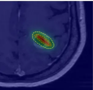
This preliminary work introduced a proof of concept for interstitial 5-ALA PDT planning (see Fig. 6). Regarding the Leksell registration, the mean relative error value reported here is under the standard MRI resolution (one millimetre). Regarding the dosimetry part, although a difference appears between irradiance values obtained by numerical and analytical models, the strong heterogeneity of GBM tissues, the minor impact of these errors on a total illumination time and the use of a non-ionizing radiation make these estimations acceptable in a 5-ALA PDT clinical context. However, analytical models are often preferred in a TPS because numerical models require the creation of a 3D mesh to solve partial differential equations and a strong optimization of the calculation. Analytical models remain much easier to implement and lead to a shorter calculation time. Nevertheless, because analytical models do not take into consideration the strong GBM tissue heterogeneity, a Monte-Carlo method accelerated by GPU computing should be more suitable.
10
Fig. 6: TPS visualization of irradiance values computed from one single 20 mm optical fibre. Iso-irradiance lines are drawn to perceive the percentage of the total irradiance: 20% (yellow), 50% (orange) and 80% (red) of the maximum irradiance delivered.
The manual segmentation that is highly user-dependent and time-consuming could be replaced by the automatic BraTumIA software to segment and classify several types of GBM tissues (grey and white matter, cerebrospinal fluid, necrosis, oedema and enhancing tumour regions) [29, 30].
Currently, no automatic optimization of the treatment planning is proposed. Several features of the optimization algorithm have to be considered. First, the optimal distance between fibres must be computed to maximize the volume treated. Fibres overlapping vessels and critical structure avoidance are a major surgical constraint for the optimization stage. Additionally, this step could be improved by the use of a map of the tumour cell density. This supplement might enable a more realistic comprehension of tumour infiltration. The optimization process can be improved by using GPU-acceleration of the analytical model. The time required to compute a whole irradiance volume with a CPU only is about one minute and can be decreased significantly in some tenths of seconds with GPU computing.
V. Conclusion
The software described here enables the loading of a DICOM set in a stereotactic Leksell frame to simulate the insertion of light sources in the patient’s brain and to estimate the irradiance and light duration for a specific treatment. Despite some approximations and the fact that several enhancements are scheduled, this preliminary work proposes a tool for the planning of an interstitial 5-ALA PDT treatment for future clinical trials. With the encouraging results observed in preclinical or clinical studies, the 5-ALA PDT can become a major adjuvant strategy in GBM management.
Compliance with ethical standards Conflicts of interests: None.
11
Ethical approval: All procedures performed in studies involving human participants were in
accordance with the ethical standards of the institutional and/or national research committee and with the principles of the 1964 Declaration of Helsinki and its later amendments or comparable ethical standards.
12
1. Maraninchi, D., N. Cerf, and P. Bousquet, Rapport sur la dynamique d'évolution des
taux de mortalité des principaux cancers en France 2010, INCa - Inserm.
2. Stupp, R., et al., Radiotherapy plus concomitant and adjuvant temozolomide for
glioblastoma. N Engl J Med, 2005. 352(10): p. 987-96.
3. Stupp, R., et al., High-grade glioma: ESMO Clinical Practice Guidelines for
diagnosis, treatment and follow-up. Ann Oncol, 2014. 25 Suppl 3: p. iii93-101.
4. Stummer, W., et al., Counterbalancing risks and gains from extended resections in
malignant glioma surgery: a supplemental analysis from the randomized 5-aminolevulinic acid glioma resection study. Clinical article. J Neurosurg, 2011.
114(3): p. 613-23.
5. Michel Lacroix, et al., A multivariate analysis of 416 patients with glioblastoma
multiforme: prognosis, extent of resection, and survival. Journal of Neurosurgery,
2001. 95(2): p. 190-198.
6. Johansson, A., et al., Protoporphyrin IX fluorescence and photobleaching during
interstitial photodynamic therapy of malignant gliomas for early treatment prognosis.
Lasers Surg Med, 2013. 45(4): p. 225-34.
7. Beck, T.J., et al., Interstitial photodynamic therapy of nonresectable malignant glioma
recurrences using 5-aminolevulinic acid induced protoporphyrin IX. Lasers in Surgery
and Medicine, 2007. 39(5): p. 386-93.
8. Stylli, S.S., et al., Photodynamic therapy of high grade glioma - long term survival. J Clin Neurosci, 2005. 12(4): p. 389-98.
9. Madsen, S.J., et al., Photodynamic therapy of human glioma spheroids using
5-aminolevulinic acid. Photochem Photobiol, 2000. 72(1): p. 128-34.
10. Aminolevulinic acid (ALA)-protoporphyrin IX fluorescence guided tumour resection. Part 2: theoretical, biochemical and practical aspects. Journal of clinical
neuroscience : official journal of the Neurosurgical Society of Australasia, 2012. 19(12): p. 1611-1616.
11. Leroy, H.A., et al., Fluorescence guided resection and glioblastoma in 2015: A
review. Lasers Surg Med, 2015. 47(5): p. 441-51.
12. Johansson, A., et al., 5-Aminolevulinic acid-induced protoporphyrin IX levels in tissue
of human malignant brain tumors. Photochemistry and photobiology, 2010. 86(6): p.
1373-1378.
13. Ishihara, R., et al., Quantitative spectroscopic analysis of 5-aminolevulinic
acid-induced protoporphyrin IX fluorescence intensity in diffusely infiltrating astrocytomas. Neurologia medico-chirurgica, 2007. 47(2): p. 53-7; discussion 57.
14. Dewas, S., et al., [Stereotactic body radiation therapy for liver primary and
metastases: the Lille experience]. Cancer Radiother, 2012. 16(1): p. 58-69.
15. Taschner, C.A., et al., Gamma Knife surgery for arteriovenous malformations in the
brain: integration of time-resolved contrast-enhanced magnetic resonance angiography into dosimetry planning. Technical note. J Neurosurg, 2007. 107(4): p.
854-9.
16. Balossier, A., et al., Role of radiosurgery in the management of pineal region
tumours: indications, method, outcome. Neurochirurgie, 2015. 61(2-3): p. 216-22.
17. Zairi, F., et al., Relevance of gamma knife radiosurgery alone for the treatment of
non-small cell lung cancer brain metastases. Clin Neurol Neurosurg, 2014. 125: p. 87-93.
18. Jacques, S.L. and B.W. Pogue, Tutorial on diffuse light transport. J Biomed Opt, 2008. 13(4): p. 041302.
13
19. Liang, X., K.K. Wang, and T.C. Zhu, Feasibility of interstitial diffuse optical
tomography using cylindrical diffusing fibers for prostate PDT. Phys Med Biol, 2013.
58(10): p. 3461-80.
20. Dupont, C., et al., Dosimetry dedicated to interstitial photodynamic treatment for
glioblastoma, in 36th Annual Conference of the American Society for Laser Medicine and Surgery. 2016, Laser Medicine and Surgery: Boston. p. 54.
21. Tedford, C.E., et al., Quantitative analysis of transcranial and intraparenchymal light
penetration in human cadaver brain tissue. Lasers in Surgery and Medicine, 2015: p.
11.
22. Farrell, T.J., et al., Modeling of photosensitizer fluorescence emission and
photobleaching for photodynamic therapy dosimetry. Appl Opt, 1998. 37(31): p.
7168-83.
23. Johansson, A., et al., Interstitial Photodynamic Therapy of Brain Tumors. IEEE Journal of Selected Topics in Quantum Electronics, 2010. 16(4): p. 841-853.
24. Tetard, M.C., et al., Interstitial 5-ALA photodynamic therapy and glioblastoma:
preclinical model development and preliminary results. Photodiagnosis Photodyn
Ther, 2015.
25. Leroy, H.-A., et al., Interstitial photodynamic therapy: Light fractionation effects on a
preclinical model of glioblastoma. Photodiagnosis and Photodynamic Therapy, 2015.
12(3): p. 347.
26. Tetard, M.C., et al., Experimental use of Photodynamic Therapy in high grade
gliomas: a review focused on 5-aminolevulinic acid. Photodiagnosis Photodyn Ther,
2014.
27. Varma, A.K. and P.J. Muller, Cranial neuropathies after intracranial
Photofrin-photodynamic therapy for malignant supratentorial gliomas-a report on 3 cases. Surg
Neurol, 2008. 70(2): p. 190-3.
28. Eljamel, M.S., C. Goodman, and H. Moseley, ALA and Photofrin fluorescence-guided
resection and repetitive PDT in glioblastoma multiforme: a single centre Phase III randomised controlled trial. Lasers Med Sci, 2008. 23(4): p. 361-7.
29. Porz, N., et al., Multi-modal glioblastoma segmentation: man versus machine. PLoS One, 2014. 9(5): p. e96873.
30. Dupont, C., et al., On Image Segmentation Methods Applied to Glioblastoma: State of
14 Annex 1
For a given slice, the four points enclosed in red circles (see Fig. 2) form a rectangle 190 x120 mm in length and the intersection of diagonals is situated on x = y = 100 mm Leksell coordinates. They also own the same x and y Leksell frame coordinates. The two points enclosed in a blue circle (see Fig. 2) indicate the location of the diagonal rod of the Leksell frame. These two points move, respectively, along the lines [1, 2] and [3, 4] according to the axial imaging modality slice location. Thus, the z Leksell coordinate can be determined using the two lengths L1,2 and L3,4 as mentioned in Fig. 2. An addition of 40 mm on the z-axis
is due to the extra height of the frame mount. Thus, for a given slice n, the Leksell coordinates
pLeskell,i of the four points 1, 2, 3 and 4 can be computed as follows:
𝑝𝐿𝑒𝑘𝑠𝑒𝑙,1,𝑛= { 100 − (1902 ) = 5 𝑚𝑚 100 + (120 2 ) = 160 𝑚𝑚 40 + 𝐿1,2 𝑚𝑚 𝑝𝐿𝑒𝑘𝑠𝑒𝑙𝑙,3,𝑛 = { 100 + (1902 ) = 195 𝑚𝑚 100 + (120 2 ) = 160 𝑚𝑚 40 + 𝐿1,2 𝑚𝑚 (6) 𝑝𝐿𝑒𝑘𝑠𝑒𝑙𝑙,2,𝑛 = { 100 − (1902 ) = 5 𝑚𝑚 100 − (120 2 ) = 40 𝑚𝑚 40 + 𝐿3,4 𝑚𝑚 𝑝𝐿𝑒𝑘𝑠𝑒𝑙𝑙,4,𝑛 = { 100 + (1902 ) = 195 𝑚𝑚 100 − (120 2 ) = 40 𝑚𝑚 40 + 𝐿3,4 𝑚𝑚 (7)
PIMA and PLeksell are thus composed of 4n 3D (x,y,z) elements:
𝑃𝐼𝑀𝐴 = { 𝑥𝐼𝑀𝐴,1,1 𝑥𝐼𝑀𝐴,2,1 𝑥𝐼𝑀𝐴,3,1 𝑥𝐼𝑀𝐴,4,1 ⋮ 𝑥𝐼𝑀𝐴,1,𝑘 𝑥𝐼𝑀𝐴,2,𝑘 𝑥𝐼𝑀𝐴,3,𝑘 𝑥𝐼𝑀𝐴,4,𝑘 ⋮ 𝑥𝐼𝑀𝐴,1,𝑛 𝑥𝐼𝑀𝐴,2,𝑛 𝑥𝐼𝑀𝐴,3,𝑛 𝑥𝐼𝑀𝐴,4,𝑛 | | | | 𝑦𝐼𝑀𝐴,1,1 𝑦𝐼𝑀𝐴,2,1 𝑦𝐼𝑀𝐴,3,1 𝑦𝐼𝑀𝐴,4,1 ⋮ 𝑦𝐼𝑀𝐴,1,𝑘 𝑦𝐼𝑀𝐴,2,𝑘 𝑦𝐼𝑀𝐴,3,𝑘 𝑦𝐼𝑀𝐴,4,𝑘 ⋮ 𝑦𝐼𝑀𝐴,1,𝑛 𝑦𝐼𝑀𝐴,2,𝑛 𝑦𝐼𝑀𝐴,3,𝑛 𝑦𝐼𝑀𝐴,4,𝑛 | | | | 𝑧𝐼𝑀𝐴,1,1 𝑧𝐼𝑀𝐴,2,1 𝑧𝐼𝑀𝐴,3,1 𝑧𝐼𝑀𝐴,4,1 ⋮ 𝑧𝐼𝑀𝐴,1,𝑘 𝑧𝐼𝑀𝐴,2,𝑘 𝑧𝐼𝑀𝐴,3,𝑘 𝑧𝐼𝑀𝐴,4,𝑘 ⋮ 𝑧𝐼𝑀𝐴,1,𝑛 𝑧𝐼𝑀𝐴,2,𝑛 𝑧𝐼𝑀𝐴,3,𝑛 𝑧𝐼𝑀𝐴,4,𝑛 𝑃𝐿𝑒𝑘𝑠𝑒𝑙𝑙= { 𝑥𝐿𝑒𝑘𝑠𝑒𝑙𝑙,1,1 𝑥𝐿𝑒𝑘𝑠𝑒𝑙𝑙,2,1 𝑥𝐿𝑒𝑘𝑠𝑒𝑙𝑙,3,1 𝑥𝐿𝑒𝑘𝑠𝑒𝑙𝑙,4,1 ⋮ 𝑥𝐿𝑒𝑘𝑠𝑒𝑙𝑙,1,𝑘 𝑥𝐿𝑒𝑘𝑠𝑒𝑙𝑙,2,𝑘 𝑥𝐿𝑒𝑘𝑠𝑒𝑙𝑙,3,𝑘 𝑥𝐿𝑒𝑘𝑠𝑒𝑙𝑙,4,𝑘 ⋮ 𝑥𝐿𝑒𝑘𝑠𝑒𝑙𝑙,1,𝑛 𝑥𝐿𝑒𝑘𝑠𝑒𝑙𝑙,2,𝑛 𝑥𝐿𝑒𝑘𝑠𝑒𝑙𝑙,3,𝑛 𝑥𝐿𝑒𝑘𝑠𝑒𝑙𝑙,4,𝑛 | | | | 𝑦𝐿𝑒𝑘𝑠𝑒𝑙𝑙,1,1 𝑦𝐿𝑒𝑘𝑠𝑒𝑙𝑙,2,1 𝑦𝐿𝑒𝑘𝑠𝑒𝑙𝑙,3,1 𝑦𝐿𝑒𝑘𝑠𝑒𝑙𝑙,4,1 ⋮ 𝑦𝐿𝑒𝑘𝑠𝑒𝑙𝑙,1,𝑘 𝑦𝐿𝑒𝑘𝑠𝑒𝑙𝑙,2,𝑘 𝑦𝐿𝑒𝑘𝑠𝑒𝑙𝑙,3,𝑘 𝑦𝐿𝑒𝑘𝑠𝑒𝑙𝑙,4,𝑘 ⋮ 𝑦𝐿𝑒𝑘𝑠𝑒𝑙𝑙,1,𝑛 𝑦𝐿𝑒𝑘𝑠𝑒𝑙𝑙,2,𝑛 𝑦𝐿𝑒𝑘𝑠𝑒𝑙𝑙,3,𝑛 𝑦𝐿𝑒𝑘𝑠𝑒𝑙𝑙,4,𝑛 | | | | 𝑧𝐿𝑒𝑘𝑠𝑒𝑙𝑙,1,1 𝑧𝐿𝑒𝑘𝑠𝑒𝑙𝑙,2,1 𝑧𝐿𝑒𝑘𝑠𝑒𝑙𝑙,3,1 𝑧𝐿𝑒𝑘𝑠𝑒𝑙𝑙,4,1 ⋮ 𝑧𝐿𝑒𝑘𝑠𝑒𝑙𝑙,1,𝑘 𝑧𝐿𝑒𝑘𝑠𝑒𝑙𝑙,2,𝑘 𝑧𝐿𝑒𝑘𝑠𝑒𝑙𝑙,3,𝑘 𝑧𝐿𝑒𝑘𝑠𝑒𝑙𝑙,4,𝑘 ⋮ 𝑧𝐿𝑒𝑘𝑠𝑒𝑙𝑙,1,𝑛 𝑧𝐿𝑒𝑘𝑠𝑒𝑙𝑙,2,𝑛 𝑧𝐿𝑒𝑘𝑠𝑒𝑙𝑙,3,𝑛 𝑧𝐿𝑒𝑘𝑠𝑒𝑙𝑙,4,𝑛 (8)
With these two vectors, a 3x3 covariance matrix S is built:
𝑆 = (
𝐶𝑜𝑣(𝑃𝐼𝑀𝐴(: ,1), 𝑃𝐿𝑒𝑘𝑠𝑒𝑙𝑙(: ,1)) 𝐶𝑜𝑣(𝑃𝐼𝑀𝐴(: ,2), 𝑃𝐿𝑒𝑘𝑠𝑒𝑙𝑙(: ,1)) 𝐶𝑜𝑣(𝑃𝐼𝑀𝐴(: ,3), 𝑃𝐿𝑒𝑘𝑠𝑒𝑙𝑙(: ,1))
𝐶𝑜𝑣(𝑃𝐼𝑀𝐴(: ,1), 𝑃𝐿𝑒𝑘𝑠𝑒𝑙𝑙(: ,2)) 𝐶𝑜𝑣(𝑃𝐼𝑀𝐴(: ,2), 𝑃𝐿𝑒𝑘𝑠𝑒𝑙𝑙(: ,2)) 𝐶𝑜𝑣(𝑃𝐼𝑀𝐴(: ,3), 𝑃𝐿𝑒𝑘𝑠𝑒𝑙𝑙(: ,2))
𝐶𝑜𝑣(𝑃𝐼𝑀𝐴(: ,1), 𝑃𝐿𝑒𝑘𝑠𝑒𝑙𝑙(: ,3)) 𝐶𝑜𝑣(𝑃𝐼𝑀𝐴(: ,2), 𝑃𝐿𝑒𝑘𝑠𝑒𝑙𝑙(: ,3)) 𝐶𝑜𝑣(𝑃𝐼𝑀𝐴(: ,3), 𝑃𝐿𝑒𝑘𝑠𝑒𝑙𝑙(: ,3))
) (9)
15 𝑄 = [ 𝑇𝑟𝑆 𝑆1,2− 𝑆2,1 𝑆2,0− 𝑆0,2 𝑆0,1− 𝑆1,0 𝑆1,2− 𝑆2,1 2 × 𝑆0,0− 𝑇𝑟𝑆 𝑆0,1+ 𝑆1,0 𝑆0,2+ 𝑆2,0 𝑆2,0− 𝑆0,2 𝑆1,0+ 𝑆0,1 2 × 𝑆1,1− 𝑇𝑟𝑆 𝑆1,2+ 𝑆2,1 𝑆0,1− 𝑆1,0 𝑆2,0+ 𝑆0,2 𝑆2,1+ 𝑆1,2 2 × 𝑆2,2− 𝑇𝑟𝑆] (10)
Eigen vectors are computed from the Q matrix and enable the building of a quaternion q expressed as q = a + b + c + d where a, b, c, d are normalized real parts of the maximum eigen values from the eigen vector. With this quaternion, we then can create matrix A that enables the conversion of image coordinates into Leksell coordinates:
𝐴 = [ 𝑎2+ 𝑏2− 𝑐2− 𝑑² 2𝑏𝑐 − 2𝑎𝑑 2𝑎𝑐 + 2𝑏𝑑 𝑡 𝑥 2𝑎𝑑 + 2𝑏𝑐 𝑎2− 𝑏2+ 𝑐2− 𝑑² 2𝑐𝑑 − 2𝑎𝑏 𝑡 𝑦 2𝑏𝑑 − 2𝑎𝑐 2𝑎𝑏 + 2𝑐𝑑 𝑎2− 𝑏2− 𝑐2+ 𝑑² 𝑡 𝑧 0 0 0 1 ] (11) where: 𝑡𝑥= 𝑃𝐼𝑀𝐴.𝑥− (𝐴0,0. 𝑃𝐿𝑒𝑘𝑠𝑒𝑙𝑙.𝑥 + 𝐴0,1. 𝑃𝐿𝑒𝑘𝑠𝑒𝑙𝑙.𝑦+ 𝐴0,2. 𝑃𝐿𝑒𝑘𝑠𝑒𝑙𝑙.𝑧) 𝑡𝑦= 𝑃𝐼𝑀𝐴.𝑦− (𝐴1,0. 𝑃𝐿𝑒𝑘𝑠𝑒𝑙𝑙.𝑥 + 𝐴1,1. 𝑃𝐿𝑒𝑘𝑠𝑒𝑙𝑙.𝑦+ 𝐴1,2. 𝑃𝐿𝑒𝑘𝑠𝑒𝑙𝑙.𝑧) 𝑡𝑧= 𝑃𝐼𝑀𝐴.𝑧− (𝐴2,0. 𝑃𝐿𝑒𝑘𝑠𝑒𝑙𝑙.𝑥 + 𝐴2,1. 𝑃𝐿𝑒𝑘𝑠𝑒𝑙𝑙.𝑦+ 𝐴2,2. 𝑃𝐿𝑒𝑘𝑠𝑒𝑙𝑙.𝑧) (12)