READ THESE TERMS AND CONDITIONS CAREFULLY BEFORE USING THIS WEBSITE. https://nrc-publications.canada.ca/eng/copyright
Vous avez des questions? Nous pouvons vous aider. Pour communiquer directement avec un auteur, consultez la première page de la revue dans laquelle son article a été publié afin de trouver ses coordonnées. Si vous n’arrivez pas à les repérer, communiquez avec nous à [email protected].
Questions? Contact the NRC Publications Archive team at
[email protected]. If you wish to email the authors directly, please see the first page of the publication for their contact information.
NRC Publications Archive
Archives des publications du CNRC
This publication could be one of several versions: author’s original, accepted manuscript or the publisher’s version. / La version de cette publication peut être l’une des suivantes : la version prépublication de l’auteur, la version acceptée du manuscrit ou la version de l’éditeur.
Access and use of this website and the material on it are subject to the Terms and Conditions set forth at
Performance of a 7.6-m diameter full-face tunnel-boring machine
designed for a Canadian coal mine
Palmer, J. H. L.; Lovat, R. P.; Marsh, J. C.
https://publications-cnrc.canada.ca/fra/droits
L’accès à ce site Web et l’utilisation de son contenu sont assujettis aux conditions présentées dans le site LISEZ CES CONDITIONS ATTENTIVEMENT AVANT D’UTILISER CE SITE WEB.
NRC Publications Record / Notice d'Archives des publications de CNRC:
https://nrc-publications.canada.ca/eng/view/object/?id=306e52aa-d7ed-44bd-a0eb-7480904b4e7a https://publications-cnrc.canada.ca/fra/voir/objet/?id=306e52aa-d7ed-44bd-a0eb-7480904b4e7aSer
TH1
IN21d
National Research Conseil national
Council Canada
BEdDG
de recherches Canada
*
PERFORMANCE OF A 7.6-rn DIAMETER FULL-FACE TUNNEL-BORING
MACHINE DESIGNED FOR A CANADIAN COAL MINE
by J.H.L. Palmer, R.P. Lovat and J.C. Marsh
Presented at
Tunnelling '85
The Fourth International Symposium
Brighton, England, 10
-
15 March 1985
Paper 4,8p.
~
3
DBR Paper No. 1270
L
Division of Building Research
ABSTRACT
A c o n t r a c t was p l a c e d f o r t h e c o n s t r u c t i o n of a
7.6
m-diameter r o c k t u n n e l b o r i n g machine. Disk c u t t e r s o r r i p p e r s c a n be employed a s d i c t a t e d by t h e r o c k c o n d i t i o n s . A l l c u t t e r changes a r e e f f e c t e d from w i t h i n t h e machine. The f i r s t 1.5 k m o f a 14.5 km t u n n e l w i t h a 20% d e c l i n e were completed a t t h e Donkin-Morien Mine, Nova S c o t i a . The a v e r a g e r a t e of advance of t h e machine was 1.8 m/h andi t s
u s a g e h a s been q u i t e s a t i s f a c t o r y .Une f o r e u s e d e
7 , 6 m
de d i a m s t r e pour l e percement d e s t u n n e l sdans l e r o c a gt15 c o w A
" - -
=
1 ' n r r r o i d ' u n c o n t r a t .--.
S e l o n l a n a t u r e du -.S'a
m o l e t t e s ou d e s d e n t s d e l ' i n t g r i e u r d e l afc
e n ~ o u v e l l e - k c o s s e , ona
e t d e p e n t e a l l a n t j u s q d s e moyenne d e 1 , 8 - . - - . - - 6 e s a t i s f a i s a n t e .TUNNELLING
#85
The fourth international
symposium, organized by
$he Institution of Mining
and Metallurgy, with the
cooperation of the British
Tunnelling Society and the
Transport and Road
Research Laboratory,
Department of Transport
10-15
March
1985
Brighton England
Paper 4
J. H. L. Palmer, R. P. Lovat and J. C. Marsh
Performance of a 7.6-m diameter full- face tunnel-boring machine designed for a Canadian coal mine
This paper will be submitted for discussion at the Tunnelling '85 symposium - to be held in Brighton,
England, from 10 to 15 March, 1985. Preprints are issued for the use of symposium registrants. All papers presented at the symposium will be published with discussion, authors' replies and name and subject indexes, in a volume of proceedings -
Tunnelling '85 - obtainable in late
1985-early 1986 from the Institution of Mining and Metallurgy,
44 Portland Place, London W 1N 4BR, England. The reproduction, in part or in whole, of material from this paper without the written permission of the Institution of Mining and Metallurgy is forbidden.
0
The Institution of Mining and Metallurgy 1985Performance of a 7.6-m diameter full-face tunnel-boring
machine designed for a Canadian coal mine
J. H. L.
Palmer IGeotechnical Section, Division of Building Research, National Research Council of Canada, Ottawa, Ontario, Canada
R. P. Lovat
Lovat Tunnel Equipment Inc., Toronto, Ontario, Canada
J.
C. Marshr Donkin-Morien Development Project, Cape Breton Development Corporation,
-
Sydney, Nova Scotia, CanadaSynopsis
In March, 1982, a contract was placed for the construction of a 7.6-m diameter rock tunnel-boring machine (TBM) t o drive haulageways for a new coal mine. Because the coal deposit is situated offshore beneath the Atlantic Ocean, the machine had to be designed to negotiate grades from - 20% to near horizontal and to be readily removed from the tunnel, which would blind-end at the intersection of the coal seam some 3.4 km from shore. The rock along the proposed alignment was expected t o vary from 1 0 to 100 MPa in compressive strength, so a further requirement was that the machine be designed to use disc cutters in the hard rock and rippers in the very soft rock. As a consequence, a design was evolved that is possibly unique.
The tunnelling machine is a full-face, fully shielded design, which can be dismantled within a tunnel cut by itself and reassembled in a similar chamber. Disc cutters or rippers can be employed as dictated by the rock conditions. All cutter and bit changes are effected from within the machine. The tunnel support, with use of steel ribs, thrust beams and wire mesh, is also assembled within the safety of the machine shield.
The machine, which has been certified for use in coal mines, was delivered in August-September, 1983, and tunnelling was begun in October, 1983. Verification and performance tests were completed in March, 1984, and mining of the first decline is under way. In mining on the 20% decline through competent sandstone, rates of 1.8 m/h and overall average progress of 1 m/h have been achieved. Although some overcutting of spoil at the face has occurred because of the steep decline, removal of the cuttings has generally been good and cutter usage has been quite satisfactory. Overall performance is comparable with that reported for TBM tunnelling in other coal mines. The TBM-mined decline was superior in quality, more economical and safer than a conventionally mined adjacent decline.
One of the earliest uses of a full-face tunnel-boring machine (TBM) in a coal mine was reported by ~ a r d i n g ' to be in about 1971 in Germany. Handewith2 reported that a TBM was used in a coal mine in the U.S.A. at about the same time. In spite of these early applications, the general acceptance of TBM for use in coal mine development in North America has yet to occur: it was, therefore, a bold step when the Cape Breton I Development Corporation (CBDC) decided in June, 1981, to use a Canadian-built TBM to drive access tunnels for a new
-
subsea coal mine near Sydney, Nova Scotia, Canada. This decision was made with the proviso that the manufacturer prove his ability to build a machine capable of boring on the required -20% grade. At that time the National Research Council of Canada (NRCC) was encouraging Lovat Tunnel Equipment Inc., producers of world-class soft ground TBM, to enter the rock TBM field. The timing was fortuitous.With strong support from the Canadian Federal Government a contract was issued in July, 198 1, to build and test an experi- mental TBM. For the purpose of the contract a used 4-m diameter soft ground TBM was modified and tested at the site of the proposed mine, but sufficiently remote from the coal deposits that the machine did not have to meet permissible standards. A total length of 173 m of tunnel was bored with the experimental TBM along the alignment of one of the declines for the Donkin-Morien mine near Sydney, Nova Scotia. The
trials were quite successful and have been reported by Palmer and co-workers.' In March, 1982, an order was placed to con- struct a 7.6-m diameter full-face shielded TBM. The machine had been delivered to the site by September, 1983, and tun- nelling commenced by overcutting the experimental tunnel in October, 1983.
Donkin-Morien mine
The Donkin-Morien mine is located on the northeastern shore- line of Cape Breton Island, about 300 km north of Halifax and 25 km east of Sydney, Nova Scotia. A vast potential coal resource lies beneath the Atlantic Ocean just offshore of Cape Perce, Nova Scotia. The coal seams of current interest outcrop on the sea bottom near shore and dip an average of 11" to the north (i.e. seaward). The western limits of several seams have been mined, but the eastern and northern extent of the deposits are essentially limited by depth and distance from land. Details of the proposed Donkin-Morien mine have been published.4s The first three seams recommended for exploration are esti- mated to contain a total potential resource of 1400 000 000 t , of which approximately 1000000000 t is considered to be recoverable. To intersect the coal seams initial plans call for two declines some 3.4 and 3.8 km long with, ultimately, close to 14.5 km of access tunnels.
Geology
The coal seams of interest are situated within the upper unit of an extensive sedimentary basin. The deposits consist of inter- bedded sandstones, siltstones, mudstones and coal seams of Carboniferous age. They strike approximately east-west and dip northward at 5 - 15O. A bed of massive grey sandstone that outcrops along the north shore of Cape Perce provides an ideal location for portals. This bed dips north at about 12" and provides good-quality rock for much of the 20% decline, but includes frequent carbonaceous siltstone and mudstone lenses. The sandstone consists of quartz and feldspar, grain sizes ranging from 0.06 to 2.0 mm. Compressive strengths vary from 30 to 100 MPa (mean, -50 MPa). The sandstone is quite abrasive. Uniaxial compressive strength tests of other rock types, which include mudstone, siltstone and laminated sand- stones, indicate strengths that vary from 10 to 100 MPa.
Machine design features
To provide contract control a verification matrix was estab- lished based on the machine specifications. This matrix contained some 140 items. Of these items, only the most pertinent are mentioned here. Major technical specifications are summarized in Table 1.
Table 1 TBM technical data
Bore diameter 7.6 m Overall length 6.3 m Overall weight 350 t
Cutters (all cutters backloading) 39 356-mm Robbins disc
6 330-mm Robbins disc
55 Lovat tungsten carbide ripper teeth Conveyors
11.5-111 primary belt, 122 cm wide 16.5-111 secondary belt, 122 cm wide Connected horsepower 2050
Cutterhead
Fully articulated and retractable Clockwise and counterclockwise rotation Variable-speed hydraulic drive, 0-4 rev/min Pentechnicon 5 platforms, 6 m long Propulsion
24 hydraulic jacks 1.7-m stroke
Cutting head thrust 1088 t @ 13 790 kPa Steering
Thrust jacks
Articulated cutterhead
Stabilizer rollers (also used for control of counter rotation) Hydraulic fluid 60/40 water/oil emulsion
Power supply
Main, 1100 V, three-phase, 60 Hz Lighting, 110 V, single-phase, 60 Hz
Equipped with mechanical rib erector, rib expander, diamond drill for probing ahead and provision for shotcreting
Certified intrinsically safe electrics Certified for use in coal mines
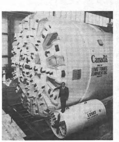
The machine (Fig. 1) was required to be capable of boring a tunnel 7.6 m in diameter on a decline of 22% (the actual decline is 20%) and at other gradients between -22% and horizontal. A penetration rate of 3 m/h in rock of 100 MPa was specified with a minimum advance on a horizontal grade of 105 m per 100-h working week over four consecutive weeks. The machine is capable of cutting softer rocks with carbide- tipped rippers when disc cutters are not appropriate. All cutters are positioned and replaced from within the machine. To
minimize ignitions a maximum cutterhead peripheral speed of 92 m/min was also specified (i.e. a maximum of 4 rev/min).
Because each decline dead-ends beneath the sea the machine had to be built in such a manner that it could be readily dis- mantled into components small enough to be transported through the completed tunnel. The largest component weighs about 27 t. Normally, a large chamber is constructed for this purpose; however, excavation of such a chamber is expensive and time-consuming. In this case there was a further consider- ation that the chamber would have to be excavated in the weak
Fig. 1 TBM - largest and smallest of the Lovat tunnel-boring machines
rocks close to the coal seam. Welding, of course, would be prohibited. Consideration of these facts led to the design of a machine that can be dismantled within a tunnel only marginally larger than its own diameter - in fact, a tunnel cut by itself. This design implied a means to handle, position and transport the pieces in the tunnel. To accomplish this a new piece of equip- ment, called an erector transporter, was designed and built.
Since the machine is fully shielded, permanent support in the form of steel ribs with wire mesh protection and steel thrust
beams can be erected within the protection of the shield. These
--
are expanded into position when the rock is exposed 6.5 mbehind the face. The shield is slightly tapered from front to rear and the head of the TBM is fully articulated.
The machine is designed to be flame- and explosion-proof. It had to be certified by the Canada Centre for Mineral and Energy Technology (CANMET) for use in a methane atmos- phere and had to meet Labour Canada standards as well as standards imposed by CBDC. Ventilation, safety, dust control and ease of maintenance were all items of concern for the design.
The TBM is equipped with a diamond drill, which is capable of probing ahead of the face (a significant safety requirement, particularly for a subsea tunnel), and can drill and obtain core samples vertically, horizontally and on several angles through the machine shield, if necessary.
Erector transporter transfer stations, construction of a railway siding, changeove from hoist to locomotive operation for material handling, etc The design and construction of the erector (ET) were under-
taken by Beaver Construction Group Limited, Dorval, Quebec, since such a specialized piece of equipment suitable for use in a gassy atmosphere was not readily available. The desired equipment was required to manoeuvre within a 7.6-m diameter tunnel while lifting and precisely positioning components weighing up to 27 t each. The largest component to be handled was 6 m in diameter and 0.5 m thick.
Fig. 2 Erector transporter lifting 30-t proof load
The ET that was developed (Fig. 2) is, in effect, a highly manoeuvrable telescopic boom mounted on an expandable, self-propelled straddle carrier. It is a diesel-hydraulic unit certified as safe for operation in an underground coal mine. It can negotiate 20% grades while carrying a load of 30 t and can be controlled and manoeuvred with sufficient precision to assemble or dismantle the TBM.
The ET was used to dismantle and reposition within simu- lated tunnel dimensions all major components of the TBM while the machine was being dismantled and shipped from the manufacturer's plant in Toronto, Ontario, to Sydney, Nova Scotia. The proven versatility of the ET is such that many other uses besides its specified functions underground are possible.
Machine performance
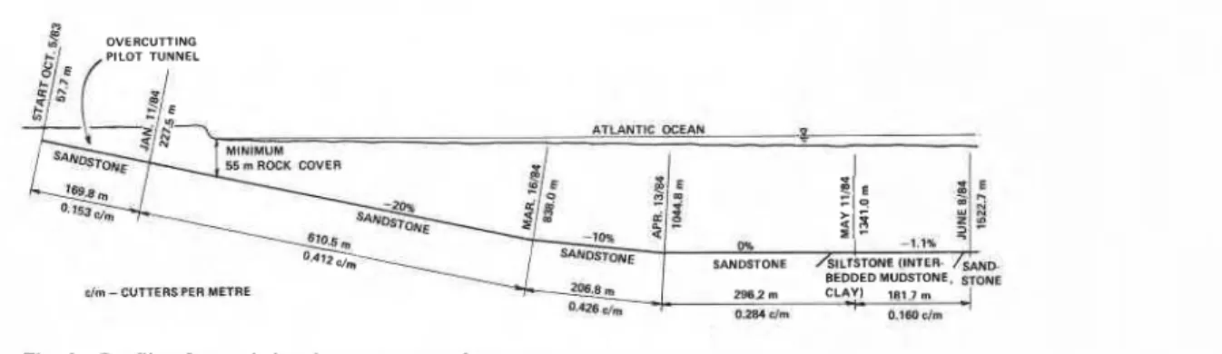
The performance over the first 1.5 km of tunnel is presented with emphasis on the 20% decline portion. There are relatively few other data published on the performance of a TBM on a decline for comparison. As shown in Fig. 3, several vertical curves have been traversed with the objective of remaining within the sandstone formation as much as possible, while still I
obtaining the desired intersection with the coal seam. Perform- ance of the machine through these curves has been excellent, but is difficult to assess quantitatively because of the other operational requirements, such as installation of conveyor belt
Penetration rate
Penetration rate is defined as the rate of advance of the TBN while mining. An average penetration rate of 1.48 m/h wa! achieved on the 20% decline from the commencement of the full-face tunnel at 227.5 m through part of the 20% to 10% transition vertical curve to 846.5 m. The maximum penetration rate was about 1.8 m/h. This rate is about 60% of the specified rate of 3 m/h. It might be argued that the lower rate is attribu table to operation on a decline, but the main reason is the limi tation of rotational speed to 4 rev/min. Rate of penetration i approximately proportional to rate of rotation, so if a normal rock TBM rotation of about 8 rev/min were permitted, a penetration rate of 3.6 m/h would be possible. The prescribed rate of 3 m/h is not otherwise achievable for this machine in rock of 100-MPa compressive strength.
Rate of advance
For the purpose of verifying the performance of the machine an evaluation was made of the rate of advance over four consecutive weeks on the 20% decline. The specified perform- ance of the machine under normal conditions was 105 m/100-h week. To fairly appraise the performance of the machine the following formula was accepted:
A x 100 Advance per 100-h week =
T- (M+ D)
where A is actual advance per week, m, T is total hours avail- able per week (i.e. three shifts
x
eight h x five days = 120 h), M is allocated maintenance time (four h x five days = 20 h) and Dis delays beyond the allocated maintenance time that could not be attributable to machine performance (e.g. power failure). On this basis the four-week average from 13 February to 11 March was 95.2 m/100-h week. It was reasoned that the machine was performing at 10070 lower efficiency than it would on a horizontal drivage; accordingly, the specified rate on a horizontal drive of 105 m/100-h week was considered to have been demonstrated.
The fundamental consideration, however, is the overall rate of progress of the tunnel. From Fig. 3 it is evident that the face was advanced from 227.5 to 838.0 m in two months, i.e. the overall progress on the 20% decline was 305 m/month. In fact, because of the normal learning curve, only 120 m was achieved in the first three weeks of January.
Operating and delay time
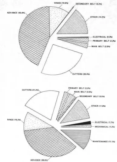
A further appreciation of the overall operation of driving the decline can be achieved by inspection of an operating and delay time chart. For the week ending 17 March (i.e. the last week of drivage of the 20% decline, including part of the transition) the chart of times is shown in Fig. 4(a). The major times were for mining (43.4%), support assembly (10.8%) and replacement of
w
-f
f E
r 9 m
SANDSTONE /SILTSTONE IINTER- / S A ~ *, m3,1m BEDDED MUDSTONE. ~ O M E
elm- W m R S PER METRE 298.2 m CLAY1 181.7 r#n
t'.*ZBcrm * 0.m chn
comparison with available time. A typical mining cycle cur- rently is about 45-50 min of mining and 10-15 min for support
ADVANCE 145.4 assembly. The next major time component is that required for
cutter changes. Clearly, an objective would be to minimize that time, which amounts to about 30-45 min per cutter change. By 24 June the total time for cutter changes had decreased signifi- cantly because of decreased cutter wear. Where the rock is soft ELECTRICAL 10.%1
PRIMARY BELT l2.W enough and methane make low enough that the rippers can be
used safely, this time loss could be almost eliminated.
Cutter usage
As was noted above, cutter changes account for a significant part of the overall time. The actual average cutter usage is shown in Fig. 3: cutter usage decreased as the job progressed, except for a small increase when the vertical curves were being negotiated. On the 20% decline an average of 0.412 cutters per metre was consumed, whereas on the horizontal drive only PRIMARY BELT 1 2 1 ~ 0.284 cutters per metre were used. The further decrease to 0.160
cutters per metre is a reflection of the change in rock type. Although the TBM was clearing rock chips from the face quite well on the 20% decline, some overcutting of the pieces was inevitable. Also, it is impossible to prevent some water accumulation at the face, so additional abrasion was caused by a slurry of sand grains. As was mentioned in the section on ELEC~RICALII.~U geology, rock abrasivity tests indicated that the sandstone was MECHANICAL I1.W very abrasive.
Cutters are being rebuilt and maintained at the mine site. All cutters removed are not necessarily rebuilt immediately, but MAINTENANCE1ll.lw may be reused in a low wear location. Fig. 5 shows the cutter changes from chainage 450.85 m to 690.71 m as a fairly typical pattern on the 20% decline. The greatest wear is experienced on the gauge cutters, as might be expected because of the adverse angle of attack of the cutter. From information such
Fig. Operating and time delay charts: (a) (top) week ending 17 as this it is easier to predict cutter wear and to plan cutter
March, 1984, and (b) average 9 January to 17 March, 1984 changes.
Ventilation and dust suppression
37 cutters (26.4%). The segment called 'other' (14.2%) is composed mainly of travel (4.8%), luncheon (2.5%), a broken hydraulic hose (1.6%), support repair (1.3%), cold oil (1.2%), an oil leak (1.0%) and survey (1.0%). During this week all maintenance was completed in the time that cutters were being changed, so maintenance time is not shown. A similar chart for the period from 9 January to 17 March is shown in Fig. 4 ( b ) . Travel (2.4%), support repair (2.2%) and luncheon (2.1%) are the major components of the segment called 'other'.
As in all TBM projects, actual machine utilization is low in
Full-face tunnel-boring machines greatly enhance dust sup- pression design, particularly for extraction-type ventilation. Unfortunately, full-face containment is a distinct disadvantage for the achievement of adequate air movement to dilute any methane gas encountered. This problem was recognized during the design of the 7 . 6 - m TBM and a series of full-scale tests was undertaken to ensure that the proposed ventilation system was adequate and to establish, if possible, optimum operating conditions in terms of head speed and rotation direction. This
TOTAL CUTTER CHANGES , I I I I I I I I I . ! l l l I , l ~ c N m " " a " a m " ~ ~ f $ ~ ~ g ~ ~ ; ; ~ ~ ~ ~ ~ F ; N " ~ g r ; ~ ~ ~ ~ g f i ~ Rg; zfisg
*
u u uCUTTER LOCATION NO. ON T.B.M.
study6 indicated that full rate forcing and exhaust ventilation effectively cleared tracer gases from the face of the machine. The two main ventilation ducts are 1.2 m in diameter and are sized to carry 28.3 m3/s of fresh air, of which 4.72 m3/s is carried to the cutting head area. Air is forced into the top of the face through two 0.47-m diameter holes in the forward bulkhead. Twenty similar-size holes are located at regular intervals around the backplate so that as the cutterhead rotates the holes align intermittently, providing a minimum of 0.75 m2
I
of open hole. Some air can also flow through a 5-cm gap between the backplate and the bulkhead. The head rotation also improves air mixing.The exhaust ducts carry 7.1 m3/s of air so that the airflow differential between exhaust and forcing ducts ensures entrap-
I .
ment of dust and methane. Exhaust air is passed through a scrubber unit, which is rated at 7.8 m3/s at 89-mm static pressure drop with a load of 63.5 kg/h of dust.Comparison with drill-blast tunnel operation
A 20Vo decline was driven by conventional drill and blast techniques parallel to that driven by the TBM. This decline was driven to the end of the 20% portion and will be completed by
I
the TBM. The declines cannot be compared exactly because thesize and conditions are not identical. For example, since the drill-blast tunnel was completed before the TBM started operation, it was practical to use that tunnel to drain water produced in the TBM drivage. A general comparison indicates, however, that the TBM was progressing about four times faster than the rate that was achieved on the drill-blast decline and the man-hours expended per metre for the TBM drive were of the order of one-third of those for the conventionally driven decline.
Additional advantages of the TBM tunnel are reduced ventilation costs as a result of a more uniform and smooth- walled tunnel, reduced long-term maintenance costs and much improved worker safety. There were threevery minor lost-time accidents in the first 1.5 km of tunnelling completed with the TBM. The economic benefits of quicker access to the coal seam and earlier mine production are also quite significant, though very difficult to quantify.
Discussion
I
The comparison of the performance of one tunnelling machinewith another is extremely difficult, even if the machines are working on the same project, because of inevitable variations in geology and other conditions. Commonly, tunnelling pro- jects are rated according to the length of tunnel completed per
C
unit of time. On this basis a comparison can be made between published records for the Selby mine in Great ~ r i t a i n , ' the Monopol colliery in ~ e r m a n y ' and the Donkin-Morien mine. Other than the fact that all three mines are coal mines, con- ditions are different for each. Nevertheless, the average advance at Selby during the first portion of the drive was reported to be about 110 m/week (90 h) or 1.2 m/h. At Monopol colliery the average advance was 280 m/month (360
It is interesting to note that the best month's progress a Monopol was 570 m or 52.5 m3/h and the best week at Selb was 150 m or 44.0 m3/h, assuming a 90-h week. This basis o comparison indicates better than average progress at th Donkin-Morien decline, in spite of the -20% grade. Th remaining portions of the project include significant time losse for installation of various mine elements, but if these times are discounted, tunnelling progress per hour is about the same. It may be concluded that the Lovat machine has performed as well as the other machines, despite the - 20% grade and the fact that this machine is the first rock TBM to be built by the company. Future prospects are certainly encouraging.
Rear-mounted disc cutters were introduced by the Robbins Company for a machine in Spain in 1970.' Recently, a machine being built by Mannesmann Demag was reportedg to include such a feature. ~ r o c k w a ~ , ' ' in an excellent summary of problems associated with incline and decline tunnel boring, pointed out the risks that are associated with going forward of a cutterhead on a decline, but also noted that load-from-behind cutters cause structural and internal accessibility design problems. The Lovat machine has the additional complication that not only the disc cutters but also a full set of rippers are rear-mounted. Design was a problem, but good accessibility has been achieved. The safety aspect alone justifies such a design not only for declines but for any tunnel drivage. In addition, ready access to the cutters for inspection and the speed of making changes are very worthwhile benefits. The full value of the dual-purpose disc cutter and ripper design has not yet been proved on this project. In the softer rock types that are expected to be encountered later, the capability of using rippers in the main portion of the face and disc cutters for the outer cuts and gauge cutting may provide significantly better rates of penetration.
Other potential design problems discussed by ~ r o c k w a ~ ' ' were lubrication, hydraulic and back-up systems: these must be carefully considered in the design. In the case of the current machine the capability had to be provided not only to operate on the 20% (1 1.3") decline but also to traverse the short 10% decline and then operate successfully on the near-horizontal grade. All transitions were completed smoothly and did not result in machine delays.
During the initial stages of the design careful consideration was given to the merits and difficulties associated with a fully shielded machine design. In very competent rock a full shield is unnecessary and probably a hindrance-In very weak rock a full shield may prevent the initiation of dangerous and costly rock falls by providing immediate support until the primary lining is expanded into place. The geology of the Donkin- Morien site indicated that even the portal sandstone stratum contained thinly bedded deposits and frequent minor carbon- aceous mudstone and siltstone lenses that would intersect the crown at a low angle and cause spalling of the roof. It was decided to minimize the length to diameter ratio (a ratio of 0.83 was achieved) and to provide maximum protection to men and equipment with a full shield. The articulated head of the machine provides extra manoeuvrability and the tapered design of the shield mitigates the likelihood of the machine becoming stuck.
h) or 0.8 m/h. By comparison, the average rate for the Donkin- Morien mine was about 1 m/h on the 20% decline. On this basis rates for the three projects agree fairly well.
A somewhat different picture emerges if a comparison is made of the actual volume of rock excavated - a criterion applied to all excavation projects except tunnels. The volume of rock removed at Selby is 26.42 m3/m, that at Monopol is 38.18 m3/m and that at Donkin-Morien is 45.36 m3/m. On this basis the average rate of excavation at Donkin-Morien was 45.36 m3/h (26.5 m3/h at Monopol and 31.7 m3/h at Selby).
Conclusions
The performance of the TBM driving the first 1.5 km of the Donkin-Morien decline indicates that the decision to use a TBM for this project was well founded. The quality of the completed tunnel (Fig. 6) is superior to that of an adjacent drill- blast decline, the economic benefits justify the initial machine cost and the improvement in worker safety is very gratifying. The -20% grade did not cause any significant machine
Fig. 6 View of completed tunnel - 20% decline
operational problem, but it did result in higher cutter use in comparison with the performance on the horizontal grade in similar material. The higher use could be attributed to over- cutting of spoil and the inability to remove all water and fines from the face. There was some indication that the advance rate was about 10% less on the - 20% grade.
Acknowledgement
The development of the TBM was jointly supported and funded by the Cape Breton Development Corporation, the Resource Development Fund of the Department of Supply and Services and the PILP program of the National Research Council of Canada. The Ministry of Energy, Mines and Resources through CANMET provided guidance and excellent cooperation in the important task of certification as well as in the ventilation test programme. Numerous other organizations and many indi- viduals contributed to the project. Beaver Underground Structures Limited provided the initiative, enthusiasm and benefit of their extensive tunnelling experience, particularly in the early stages of the project. NEI Mining Equipment co- ordinated the design of the electrical circuits and supplied much of the electrical equipment. Basic Hydraulics coordinated the design of the hydraulic system and supplied some of the hydraulic components.
This paper is a contribution from the Division of Building Research, National Research Council of Canada and is pub- lished with the approval of the Director of the Division.
References
1. Harding P . G . TBM's stay down the mine. Tunnels Tunnell., 13, June 1981, 67.
2. Handewith H . J. TBM tunnels in the western hemisphere - an overview. Tunnell. Technoi. Newsletter no. 41, March 1983, 1-8. 3. Palmer J . H . L. Cox W. and Lovat R. Construction and perform- ance of a Canadian rock tunnel boring machine. In Rock breaking and
mechanical excavation: 14th Canadian rock mechanics symposium, Vancouver, May 1982 (Montreal: Canadian Institute of Mining and
Metallurgy, 1984), in press. (CIM Spec. Vol.)
4. Branch S, N. Devco aims for 95 per cent recovery at Donkin colliery.
Can. Min. J., 103, April 1982, 21-32 (5 p.).
5. Marsh J . C. el al. The Donkin-Morien mine: building the mine of the future. Paper presented at the second coal operators conference, Sydney, Nova Scotia, Oct. 1983, 24 p.
6. Stokes A. W. and Stewart D. B. Ventilation trials of a full-face tunnel-boring machine. In Mine ventilation: third international
conference, Harrogate, 1984 Howes M. J . and Jones M. J. eds
(London: IMM, 1984), 83-8.
7. Tunnicliffe J. F. Spine roads at Selby. Tunnels TunneN., 15, March 1983, 57-9.
8. The Robbins Company. Advertisement in Tunnels Tunnell., 16, April 1984, 40-1.
9. New German TBM is put to work. Tunnels Tunnell., 13, May 1981, 7.
10. Brockway J. E. Incline/decline boring with tunnel boring machine. In Proceedings ofthe 1983 rapid excavation and tunneling conference,
Chicago Sutcliffe H. and Wilson J. W. eds (New York: Society of
Mining Engineers of AIME, 1983), vol. 2, 743-60.
T h i s p a p e r , w h i l e b e i n g d i s t r i b u t e d i n r e p r i n t form by t h e D i v i s i o n of B u i l d i n g R e s e a r c h , remains t h e c o p y r i g h t of t h e o r i g i n a l p u b l i s h e r . It s h o u l d n o t be r e p r o d u c e d i n whole