Closed-loop pallet manipulation in unstructured environments
The MIT Faculty has made this article openly available.
Please share
how this access benefits you. Your story matters.
Citation
Walter, M.R. et al. “Closed-loop pallet manipulation in unstructured
environments.” Intelligent Robots and Systems (IROS), 2010 IEEE/
RSJ International Conference on. 2010. 5119-5126. ©2010 IEEE
As Published
http://dx.doi.org/10.1109/IROS.2010.5652377
Publisher
Institute of Electrical and Electronics Engineers / Robotics Society of
Japan
Version
Final published version
Citable link
http://hdl.handle.net/1721.1/63145
Terms of Use
Article is made available in accordance with the publisher's
policy and may be subject to US copyright law. Please refer to the
publisher's site for terms of use.
Closed-loop Pallet Manipulation in Unstructured Environments
Matthew R. Walter
∗, Sertac Karaman
†, Emilio Frazzoli
†, Seth Teller
∗∗Computer Science and Artificial Intelligence Laboratory †Laboratory for Information and Decision Systems
Massachusetts Institute of Technology Massachusetts Institute of Technology
Cambridge, MA, USA Cambridge, MA, USA
{mwalter, teller}@csail.mit.edu {sertac, frazzoli}@mit.edu
Abstract— This paper addresses the problem of autonomous
manipulation of a priori unknown palletized cargo with a robotic lift truck (forklift). Specifically, we describe coupled perception and control algorithms that enable the vehicle to engage and place loaded pallets relative to locations on the ground or truck beds. Having little prior knowledge of the objects with which the vehicle is to interact, we present an estimation framework that utilizes a series of classifiers to infer the objects’ structure and pose from individual LIDAR scans. The classifiers share a low-level shape estimation algorithm that uses linear programming to robustly segment input data into sets of weak candidate features. We present and analyze the performance of the segmentation method, and subsequently describe its role in our estimation algorithm. We then evaluate the performance of a motion controller that, given an estimate of a pallet’s pose, is employed to safely engage each pallet. We conclude with a validation of our algorithms for a set of real-world pallet and truck interactions.
I. INTRODUCTION
We have developed a robotic forklift for autonomous ma-terials handling in the outdoor, semi-structured environments typical of disaster relief and military storage warehouses [1]. The system performs typical warehouse tasks under the high-level direction of a human supervisor, notably picking up, transporting, and placing palletized cargo between truck beds and ground locations in the environment. Integral to the system is the robot’s ability to accurately localize and safely manipulate unknown pallets despite their variable geometry, the uneven terrain, and the unknown truck geometry.
Successfully picking up a pallet from a truck with a 2700 kg forklift, given perfect information regarding the poses of the robot, pallet, and truck, is relatively easy. In real settings, the challenges lie in accurately controlling the nonholonomic lift truck so as to safely insert the tines within the pallet’s slots. With little a priori information, however, the system must also detect the pallet and the truck bed, and subsequently maintain an accurate estimate for their structure and pose while approaching and engaging the pallet. These tasks are made difficult by variability in pallet and truck geometry together with limited available sensing. For example, while certain features of cargo pallets are present across most pallets (i.e., roughly rectilinear, generally flat, usually two insertion points designed for forklift tines), the geometry of pallets is highly variable. The forklift must use onboard sensing to recover the pallet geometry in order to correctly insert the lifting tines; unlike
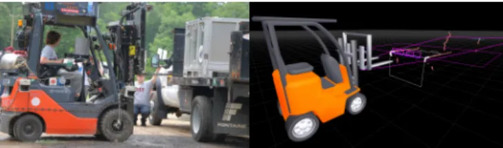
Fig. 1. The prototype forklift that is the host platform for the mobile manipulation algorithm presented in the paper. The vehicle autonomously detects and engages unknown pallets, picking them up from, and placing them onto the ground or the bed of a truck. The rendering on the right depicts the corresponding output of the pallet and truck estimation algorithms.
many small-object manipulation strategies, it is not possible to use manipulator compliance or feedback control strategies to ease insertion. Even small forklifts designed for indoor warehouses can exert tons of force; the tines are extremely rigid and cannot be instrumented with the tactile sensing necessary for feedback control strategies for manipulation. As a result, attempting to insert tines incorrectly can damage or destroy the pallet (or its load) before the failure can be detected and corrected.
In addition, a pallet’s appearance poses challenges for per-ception. The physical pallet structure is quite sparse, roughly 1 m square with a height of 15 cm and inserts that are each 30 cm wide. This sparsity affords limited observation of the manipuland with views dominated largely by LIDAR returns from the pallet’s load as well as the surface on which the pallet lies. Similarly, a truck’s undercarriage comprises most of the view of a vertically-scanning LIDAR, with limited returns arising from the vertical and horizontal faces of the truck bed. Further complicating the problem of accurately detecting and estimating the pallet and truck poses is the fact that, while they are themselves rigid, the forklift’s tines and carriage, to which the LIDARs are mounted, are not rigidly attached to the vehicle, which limits the accuracy of extrinsic calibration.
This paper presents a coupled perception and control strategy that addresses these challenges, enabling the fork-lift to manipulate unknown pallets within semi-structured, outdoor environments. We first introduce the overall robotic platform, briefly describing the aspects that are pertinent to our mobile manipulation work. We then describe a general strategy for pattern detection that identifies candidate linear
The 2010 IEEE/RSJ International Conference on Intelligent Robots and Systems
structure within noisy 2D LIDAR scans. We then describe pallet and truck estimation algorithms that utilize this pattern recognition tool in a series of classifiers to detect returns from the pallet structure and truck bed. The algorithms utilize positive detections as inputs to a set of filters that maintain estimates for the pallet and truck poses throughout engagement. We describe the control strategy that we use to servo the pose of the vehicle and tines. Finally, we present the results of a series of validation tests that demonstrate the accuracy and limitations of our mobile manipulation strategy.
II. RELATEDWORK
There has been considerable work in developing mobile manipulators to accomplish useful tasks in populated envi-ronments. This work has largely focused on the problems of planning and control [2], [3], which are not inconsiderable for a robot with many degrees of freedom and many actuators capable of exerting considerable force and torque. These efforts generally take one of two approaches: either assume a high-fidelity kinodynamic model and apply sophisticated search to solve for a feasible control plan [4]–[6], or use re-active policies with substantial sensing and feedback control (either visual [7] or tactile [8], [9]) to avoid the requirements of a model.
In regards to perception challenges, there has been ex-tensive work addressing the problems of object segmenta-tion, classificasegmenta-tion, and estimation based upon range data. In particular, early work by Hebert et al. [10] describes algorithms for object detection and recognition with an outdoor robot using laser scan data. Hoffman and Jain [11] present a method to detect and classify the faces comprising 3D objects based on range data. Similarly, Newman et al. [12] propose a model-driven technique that leverages prior knowledge of object surface geometry to jointly classify and estimate surface structure. Researchers have also extended the robustness of image segmentation [13] and object model parameter estimation [14], [15] using randomized sampling to accommodate range images with many outliers. In general, these techniques require range images of the scene, which, in the case of our platform, are subject to systematic error due to the pliancy of the forklift structure to which the LIDARs are mounted.
The specific problem of developing an autonomous lift truck that is able to pick up and transport loaded pallets is not new [16]. The same is true of pallet detection and localization, which pose interesting perception challenges due to their sparse structure. Most of this work, however, differs significantly from our own, in that it assumes a clean, highly-structured environment, does not generalize across varying pallet geometry [17]–[19], and does not consider the problem of placing pallets onto and picking pallets off of unknown truck beds.
III. SYSTEMOVERVIEW
Our platform is a 2700 kg Toyota forklift with drive-by-wire modifications enabling computer-based control of the vehicle and mast (i.e., tine height and forward/backward tilt)
Fig. 2. The forklift detects pallets with a single horizontally-scanning LIDAR, and truck beds with a pair of vertically-scanning LIDARs.
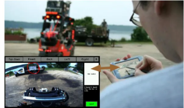
Fig. 3. Forklift being commanded, via the tablet interface, to pick up a pallet from a truck bed.
actuation. The platform is equipped with laser range finders for object detection as well as a forward-facing camera that provides images to a remote user’s command interface. We estimate the vehicle’s pose via dead-reckoning based upon wheel encoder velocity measurements together with heading measurements from an integrated GPS/IMU.
Pallet detection relies upon a single Hokuyo UTM laser range finder with a 30 m range and a 140 degree field-of-view (limited by mounting enclosure). The unit is mounted at the elbow of one of the forklift’s tines and scans in a horizontal plane situated slightly above the tine’s top surface (Figure 2). Meanwhile, the truck bed estimation algorithms that follow utilize a pair of UTM laser range finders (30 m range, 270 degree FOV) mounted to the left and right sides of the carriage assembly with a vertical scan plane. All three LIDARs move in tilt with the mast and height with the carriage.
The forklift operates autonomously based upon high-level directives from a user who commands the system via a hand-held tablet computer [1], [20]. In the case of pallet engagement tasks, the user directs the platform to pick up a pallet from the ground or a truck bed, or to place a pallet at a specified, unoccupied location on the ground or truck. The user indicates the desired pallet to engage by circling it within the image from the vehicle’s forward-facing camera, which is displayed on the tablet (Figure 3). Similarly, the user identifies a desired pallet placement location by circling the region in the camera image. We project these
based gestures into the world frame, yielding a corresponding
volume of interest.
In the subsequent sections, we explain how the robot autonomously manipulate pallets given directives of this form.
IV. FASTCLOSESTEDGEDETECTION
FROMLASERRANGEFINDERDATA
In this section, a novel efficient algorithm that identifies the closest edge in LIDAR data is proposed. Two closest edge detection problems are studied. The first assumes that the orientation of the edge is known and estimates the distance of the edge from the sensor. The second relaxes this assumption and estimates both the distance and orientation of the edge. Inspired by similar problems in learning with kernel methods [21], we formulate the first variant of the problem as a linear program, the dual of which is shown
to be solvable in O(n min{ν, log n}) time, where n is the
number of points andν is a problem-specific parameter. Note
that solving the original linear program with, for instance, the
interior point algorithm requires O(n3.5) time in the worst
case [22]; hence, exploiting the structure of the dual program results in significant computational savings, facilitating real-time implementation. In the second variant of the problem, we propose a heuristic algorithm that employs the algorithm for the first variant a constant number of times. Sections V and VI describe the use of both algorithms as a basis to detect pallets and trucks, respectively.
A. Closest Edge Detection with Known Orientation Consider the first variant of the closest edge detec-tion problem. To define the problem more formally, let
X = {xi}i∈I, whereI = {1, 2, . . . , n}, be the set of points
in the two dimensional Euclidean space R2, representing
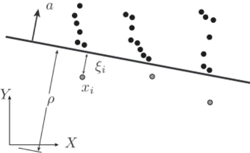
the data sampled from a planar laser range finder. Fig-ure 4 presents a simple example with laser returns that are representative of those from a pallet face. Without loss of generality, let the sensor lie in the origin of this Euclidean
space and be oriented such that its normal vector is[1, 0]⊤.
Let a ∈ R2 denote a normalized vector, i.e., k a k = 1.
Informally, the problem is to find the distance ρ from the
origin to the line that separates all data points in X , except
a few outliers, from the origin. More precisely, for all points
xi ∈ X , except a few outliers, ha, xii ≥ ρ holds, where
h·, ·i denotes the dot product, i.e., the distance of xi to the
origin when projected along the vector a. Let ξi represent
the distance of pointxi to the separating line if the distance
from the origin to xi (projected along a) is less than ρ;
otherwise, let ξi be zero. That is ξi = max (ρ − ha, xii, 0)
(see Figure 4).
Given a line described by a normal a and distance ρ, a
pointxi withξi > 0 is called an outlier with respect to the
line(a, ρ). We formulate the closest edge detection problem
as maximization of the following function: ρ − CPi∈Iξi,
where C is a constant problem-dependent parameter. The
maximization represents the trade-off between two
objec-tives: maximizing the distance ρ of the separating line to
ρ xi
a
ξi
X Y
Fig. 4. A graphical representation of the closest edge detection problem for 2D laser returns from a pallet face. The three grey points are outliers with respect to the line(a, ρ).
the origin and minimizing the total distancePi∈Iξi of the
outliers to line(a, ρ). Notice that C = 0 renders ρ = ∞, in
which case all data points will be outliers.C → ∞, on the
other hand, allows no outliers in a feasible solution. We first consider the case in which no outliers are per-mitted (C → ∞) and the relatively easy problem of finding
the distance ρ of the line with normal a to the origin such
that ρ is maximum and the line separates all points in X
from the origin. Notice that a na¨ıve algorithm that computes
the distance ofxi from the origin for all i ∈ I and returns
the minimum distance solves this problem. Notice also that
this algorithm runs in time O(n). Indeed, it can be shown
that any deterministic algorithm that solves this problem has
to run in time Ω(n). However, due to the noise embedded
in the laser range finder data, especially for LIDAR returns arising from the corners of the scanned object, this solution may provide noisy information. Precisely for this reason, the aforementioned formulation of the closest edge detection problem includes an extra term in the objective function so as to filter out such noise. The rest of this section details an algorithm that solves the closest edge detection problem while incurring small extra computational cost.
The closest edge detection problem can be formulated as a linear program as follows:
maximize ρ −1 ν X i∈I ξi, (1a) subject to di≥ ρ − ξi, ∀i ∈ I, (1b) ξi ≥ 0, ∀i ∈ I, (1c)
where ρ ∈ R and ξi ∈ R are the decision variables, and
ν ∈ R is a parameter such that ν = 1/C. The term di =
ha, xii is the distance of point xito the origin when projected
alonga.
For computational purposes, it is useful to consider the dual of the linear program (1):
minimize X i∈I diλi, (2a) subject to X i∈I λi= 1, ∀i ∈ I, (2b) 0 ≤ λi≤ 1 ν, ∀i ∈ I, (2c)
where λi are called the dual variables. Let(ρ∗, ξ1∗, . . . , ξn∗)
be the optimal solution to the linear program (1) and
(λ∗
1, . . . , λ∗n) be the optimal solution of the dual linear
program (2). The optimal primal solution is recovered from
the dual solution as ρ∗=P
i∈Iλ∗idi.
The dual linear program is particularly interesting for computational purposes. Strictly speaking,
Proposition IV.1 Algorithm 1 runs in O(n min{log n, ν})
time and solves the dual linear program(2).
Algorithm 1, DUALSOLVE, takes the parameter ν, the
normal vector a, and the set X as an input and returns an
indexed set {λi}i∈I of values for the dual variables. The
DUALSOLVE algorithm employs two primitive functions.
SORT takes an indexed set {yi}i∈I as an input, where
yi∈ R, and returns a sorted sequence of indices J such that
yJ (j)≤ yJ (j+1) for all j ∈ {1, 2 . . . , |I|}. MIN, meanwhile,
returns the indexj of the minimum element in a given index
set, i.e.,yj ≤ yj′ for allj′∈ J .
Firstly, notice that the elementary operations in
DUALSOLVE require only additions, multiplications,
and the evaluation of cross products, all of which can be computed without computation of any trigonometric function. Apart from its theoretical computational guarantees ensured by Proposition IV.1, this particular property of Algorithm 1 makes it fast in practice as well. Secondly, notice also that with Algorithm 1, one can solve the mathematical program (1). Let us denote this procedure
with DISTFIND(ν, a, X ) (see Algorithm 2). Clearly,
DISTFINDalso runs in timeO(n min{log n, ν}).
Algorithm 1: DUALSOLVE(ν, a, X ) for alli ∈ I do λi:= 0; for alli ∈ I do di:=< a, xi >; D := {di}i∈I; iflog |D| < ν then J := SORT(D); forj := 1 to ⌊ν⌋ do λJ (j):= 1/ν; λJ (⌊ν⌋+1):= 1 − ⌊ν⌋/ν; else fori := 1 to ⌊ν⌋ do j := MIN(D); λj:= 1/ν; D := D \ {dj}; j := MIN(D); λj:= 1 − ⌊ν⌋/ν; return{λi}i∈I
The next sections present pallet and truck detection al-gorithms, which employ the DISTFIND algorithm heavily.
The value ν influences the effectiveness of the detection
Algorithm 2: DISTFIND(ν, a, X )
for alli ∈ I do di:=< a, xi>;
{λi}i∈I:= DUALSOLVE(ν, a, X );
ρ :=Pi∈Iλidi
algorithms. Although the choice of ν is generally
problem-dependent, we present a couple of its interesting properties before moving on with the detection algorithms.
Proposition IV.2 mini∈Idi≤ ρ∗.
This proposition merely states that the distance returned by
DISTFIND is never less than the distance of any of the
points inX to the origin. That is, the line that separates the
origin from the data points either passes through at least one of the data points, or there exists at least one data point that is an outlier with respect to the line. The following proposi-tion indicates an important relaproposi-tion between the number of
outliers and the parameterν.
Proposition IV.3 The parameterν is an upper bound on the
number of outliers with respect to the the line(a, ρ∗).
The proofs of these propositions are omitted for lack of space.
B. Closest Edge Detection with Unknown Orientation If the orientation is not known, we invoke DUALSOLVE
a constant number of times for a set {ai}i∈{1,2,...,N } of
normal vectors, each oriented with angleθirelative to the
X-axis, whereθi are uniformly placed on the interval between
θ1 = θmin and θN = θmax (see Algorithm 3). After each
invocation of DUALSOLVE, a weighted averageziof the data
points is computed using the dual variables returned from
DUALSOLVEas weights. Using a least squares method, a line
segment is fitted to the resulting points{zi}i∈{1,2,...,N } and
returned as the closest edge as the tuple (z′, a′, w′), where
z′ is the position of the mid-point,a′ is the orientation, and
w′ is the width of the line segment.
Algorithm 3: EDGEFIND(ν, X , θmin, θmax, N )
forj := 1 to N do
θ := θmin+ (θmax− θmin)j/N ;
a := (cos(θ), sin(θ)); {λi}i∈I:= DUALSOLVE(ν, a, X ); zj:=Pi∈Iλixi; (z′, a′, w′) := LINEFIT({z j}j∈{1,2,...,N }); return(z′, a′, w′)
C. The Hierarchical Classification Framework
Pallet and truck perception algorithms that we introduce in the next two sections run DISTFIND or EDGEFIND
over sets {Xk}k∈K of data points to extract a set {fk}k∈K
of features from the data. In most cases, these features correspond to real-world structure, such as the existence of slots in an edge returned by EDGEFIND, or the height of the truck bed detected using DISTFIND.
The data sets Xk can be LIDAR returns from different
sensors, or returns from the same sensor but acquired at
different time intervals. In some other cases, Xk are
ac-quired from a single scan of the same sensor, but Xk+1 is
determined from the featuresf1, f2, . . . , fk of the data sets
X1, X2, . . . , Xk. Yet, no matter how the data sets {Xk}k∈K
are selected, the set {fk}k∈K of features are generated
using intuitive algorithms that employ either DISTFIND or EDGEFIND. These features are then compared with a
nominal set{ ¯fk}k∈K of features, for instance by computing
the distancek{fk}k∈K−{ ¯fk}k∈Kk according to some norm;
if the distance is within acceptable limits, the set {Xk}k∈K
of data sets is marked as including the object that is to be perceived from the LIDAR data.
V. PALLETESTIMATION
The algorithms described in Section IV are next used to design effective heuristic methods to detect pallets from a single LIDAR scan. We utilize this detection method as the basis for batch detection and subsequent filtering.
The algorithms described in this section can be used to estimate both the pose and geometry of pallets of various types and sizes. Most pallets used in industrial applications have distinctive features, namely two tine slots and an overall width that varies between 0.9 m to 1.5 m. Moreover, the two slots generally have the same width and are offset symmetrically with respect to the mid-point of the pallet face. Our pallet estimation algorithms first identify the closest edge in a single laser scan and then look for these distinct features in the edge. The features are identified by invoking calls to
DISTFINDand EDGEFIND.
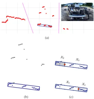
As a step prior to online filtering, we would like to extract the aforementioned features and detect pallets that lie within the user-provided volume of interest (Section III). Since our main interest is online filtering, the detection is carried out using only a single scan (Figure 5) instead of accumulated laser scans. However, assuming that the pallet roll angle is close to the that of the lift truck during active scanning, several detections obtained at different heights can be used for batch detection purposes as well, with essentially no modifications to the detection algorithm. Indeed, this strategy is employed in this work.
Given a single LIDAR scan, the pallet detection algorithm
works as follows. LetX be the set of LIDAR points obtained
from the laser range finder mounted on the tine. First,
the algorithm culls the points from X that lie within the
region of interest, forming a subset X1 (Figure 5).
Subse-quently, we call EDGEFIND onX1to detect the closes edge
(zpallet, apallet, wpallet), which constitutes a candidate pallet
face. The algorithm utilizes the output to compute the width of the pallet face, which constitutes the first classification
feature, f1 = (wpallet). Second, we form a subset X1′ that
contains all those points inX1that lie within a box of depth
ǫ, width wpallet, and orientationapallet, centered at zpallet (see
the blue box in Figure 5).1 Third, the algorithm proceeds to
estimate the slot geometry, partitioningX′
1 into four sets of
pointsX2,X3, X4, and X5. Intuitively, the set X2 includes
those points in X′
1 left (perapallet) of the center by at least
25 cm. Similarly,X4 is the set of all those points inX1′ that
(a)
(b) (c)
Fig. 5. (a) A single pallet scan and the user gesture projected on the world indicating boundaries of the region of interest (pink). (b) Points in the region of interest as well as the line detection and the associated box. (c) The data sets Xiwith i= 2, 3, 4, 5 and their origins shown as red dots.
are at least 25 cm right of center. The sets X3 and X5 are
the complements ofX2andX4, respectively (Figure 5). The
points inX2andX3are translated such that the origin is the
point that is to the left of the box and is 25 cm away from
the center. Similarly, the points inX4 andX5are translated
such that their origins are to the right of the box and 25 cm away from the center. Subsequently, the algorithm runs the
DISTFINDfunction onXifor alli = 2, 3, 4, 5 and notes the
distance returned by the DISTFIND algorithm as the feature
fi associated with data setXi. These features are denoted as
f2 = (δleftfar), f3 = (δnearleft), f4 = (δfarright), and f5 = (δrightnear).
Note that, intuitively, δfar
left is the distance from the far side
of the left slot to the center of the pallet face and similar intuition applies to other features. Finally, the algorithm
computes the widthwleftandwrightof the left and right slots.
These features are compared with nominal values within the framework of Section IV-C. If the features are within acceptable bounds, the algorithm yields a positive pallet detection (zpallet, apallet, wpallet, wleft, wright, xleft, xright), where
xleft andxrightare the distance of the center of left and right
slot locations computed directly from the featuresf2, . . . , f5;
otherwise it reports no pallet detection. For this work, we hand-tuned the nominal values of the features as well as their acceptable bounds; however, they can, in principle, be learned from training data. We leave this for future work.
1We use ǫ= 20cm and have found empirically that values between 10 cm
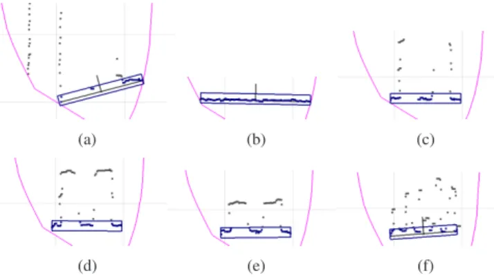
For batch detection, we actively scan the volume of interest by actuating the lift truck’s mast and collecting pallet detections at various heights. A classification algorithm then first checks whether there is a set of detections that span a height consistent with that of typical pallets and that are mutually consistent in terms of Mahalanobis distance. If so, the batch detection algorithm outputs the pallet detection averaged over this set of detections as well as the detection heights. Subsequently, we initialize a Kalman filter over the pallet detection states with the average detections and update the filter with any new detections. An active scanning operation is shown in Figure 6.
(a) (b) (c)
(d) (e) (f)
Fig. 6. Output of the pallet detection algorithm as a pallet on a truck bed is being actively scanned, sorted by increasing height. (a-b) LIDAR returns from the undercarriage and the truck bed are rejected as pallet candidates. (c-e) LIDAR returns from the pallet face are identified as the pallet. (f) The load on the pallet is correctly ruled out as a candidate pallet face.
VI. TRUCKBEDESTIMATION
This section describes our truck detection algorithms, which enable the forklift to manipulate pallets with respect to unknown truck beds. Our approach to truck estimation em-ploys a Kalman filter to track the truck’s pose online, namely the bed’s height off the ground, it’s 2D position, and it’s relative heading. We initialize the filter with a conservative prior inferred from the user’s image-relative pen gesture. We then update the filter online based upon detections extracted from the two vertically-scanning LIDARs mounted on both sides of the carriage.
The truck detection algorithm operates within the classi-fication framework described in Section IV-C. We process individual scans from the left and right laser range finders to extract two feature pairs that correspond to the truck bed height and its distance from the forklift. We then check these features for mutual consistency and against a coarse prior before yielding an observation of the truck’s height, position, and orientation.
Strictly speaking, let Xleft and Xright be the point sets
acquired via the two vertically-scanning laser range finders.
LetX1be the set of all those points inXleftthat are above the
current ground estimate. The truck bed detection algorithm
uses DISTFIND to detect the distance dleft of these points
to the sensor, which is the element of the first feature
f1 = (dleft) extracted for classification. Let X2 be the set
dright
hright
Fig. 7. Truck bed detection algorithm depicted on the raw data acquired from sensor mounted to the right of the mast.
of all those points in set X1 that are at least dleft and at
mostdleft+ ǫ away from the sensor. Moreover, let the points
inX2 be translated such that their center isdleft away from
sensor and 5 m above the ground (see Figure 7). Next, the algorithm employs DISTFIND to determine the distance
hleft of these points from the ground, which is noted as
the second feature f2 = (hleft). Similarly, we employ the
same procedure with Xright to obtain the sets X3 and X4
and two additional features, f3 = (dright) and f4 = (hright).
Comparing the left and right features for mutual consistency and against a coarse prior over truck pose, valid estimates
yield a truck bed detection(ztruck, atruck, htruck). We compute
the height of the truck bedhtruck as the average of hleft and
hright. We determine the 2D locationztruck by first projecting
the ray induced by the center of the user’s pen gesture onto
a plane that is parallel with the ground and of heighthtruck.
We then intersect this projection with the line that passes
through the 2D points from the left and right scans,zleftand
zright.
With each truck-based manipulation, we initialize a Kalman filter with a conservative prior (zpriortruck, apriortruck, hpriortruck) inferred from the user’s gesture and a nominal height of hpriortruck = 1 m. First, we project a ray into the world through the center of a circle fit to the image gesture. Intersecting this ray with a plane parallel to the ground and at a height ofhpriortruck yieldsz
prior
truck. We then estimate the orientationa prior truck
as the unit vector oriented from the forklift to ztruckprior. Upon
initialization, the filter then updates the estimates based upon observations provided by the aforementioned truck detection algorithm. Figure 8 shows a sequence of estimates for a pallet drop-off operation.
VII. CONTROLALGORITHMS
This section presents the feedback control algorithm that steers the robot from an initial position and heading to a final position and heading. The algorithm is tailored and tuned for precise pallet engagement operations.
Let zinitial and ainitial be the robot’s initial position and
orientation, wherezinitial is a coordinate Euclidean plane and
ainitial is a normalized two-dimensional vector. Similarly, let
zfinal and afinal be the desired final position and orientation
of the robot. (In our application,zfinalandafinalrepresent the
pallet position and orientation.) Without loss of generality, letzfinal= (0, 0) and afinal= (1, 0) be oriented toward the
X-axis (see Figure 9). Similarly, leteybe the distance between
zinitial andzfinal along the direction orthogonal toafinal, and 5124
(a) (b)
(c) (d)
Fig. 8. Truck bed estimation. The initial estimate of the truck bed is determined from the user pen gesture. (b-d) As the robot drives toward the truck, detections are used to update the Kalman filter estimate for the truck’s pose. (d) The bot drops off the pallet at the location on the truck indicated by the user’s pen gesture.
ey eθ ainitial af inal X Y
Fig. 9. Illustration of the controller algorithm.
let eθ be the angle between the vectors ainitial and afinal,
eθ= cos-1(ainitial· afinal). Finally, let δ be the steering control
input to the robot. In this work, we use the following steering control strategy for pallet engagement operations:
δ = Kytan-1(ey) + Kθeθ, (3)
where Ky and Kθ are controller parameters. Assuming a
Dubins vehicle model [23] of the robot as in
˙z = (cos θ, sin θ) (4a)
˙θ = tan-1(δ), (4b)
the nonlinear control law (3) can be shown to converge such
that ey → 0 and eθ → 0 holds, if −π/2 ≤ eθ ≤ π/2 is
initially satisfied [24].
VIII. EXPERIMENTALRESULTS
This section analyzes the pallet engagement system de-scribed above. The closed-loop pallet engagement algorithms were tested extensively on the hardware described in Sec-tion III, at two outdoor warehouses. Both testing sites have packed gravel terrain with small rocks and mud. In these experiments, we commanded the bot to pick up pallets from different locations on the ground as well as from truck beds, and recorded the lateral position and orientation of the robot with respect to the pallet in each test as reported by the robot’s dead reckoning module. Note that the experiments were conducted with different types of pallets that, within each type, exhibited varying geometry (i.e., width, slot location, and slot width). The pose of the pallet relative to
the truck and the truck’s pose relative to the forklift also varied. −4 −2 0 2 4 0 1 2 3 4 5 6 7 8 9 10 x (meters) y (meters) 0 0.92 1.84 2.76 3.68 4.6 5.53 6.45 7.37 8.29 9.21 Failed Detection
(a) Relative Angle (Truck)
−4 −2 0 2 4 0 1 2 3 4 5 6 7 8 9 10 x (meters) y (meters) 0 1.4 2.8 4.2 5.6 7 8.4 9.8 11.2 12.6 14 Failed Detection
(b) Cross Track Error (Truck)
−4 −2 0 2 4 0 1 2 3 4 5 6 7 8 x (meters) y (meters) 0 0.87 1.74 2.62 3.49 4.36 5.24 6.11 6.99 7.86 8.73 Failed Detection Failed Engagement
(c) Relative Angle (Ground)
−4 −2 0 2 4 0 1 2 3 4 5 6 7 8 x (meters) y (meters) 0 1.2 2.4 3.7 4.9 6.1 7.4 8.6 9.8 11.1 12.3 Failed Detection Failed Engagement
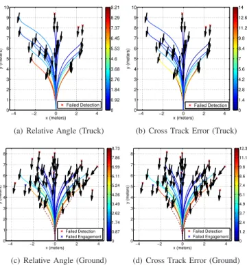
(d) Cross Track Error (Ground) Fig. 10. Results of the validation tests for pallet engagements from (a-b) a truck bed and (c-d) the ground. Each path represents the robot’s trajectory during a successful pickup. A red ‘x’ denotes the initial position of the robot for a failed engagement. Arrows indicate the robot’s forward direction. All poses are shown relative to that of the pallet, centered at the origin with the front face along the x-axis. The trajectories are colored according to (a), (c) the relative angle between the pallet and the robot (in degrees) and (b), (d) the cross track error (in cm) immediately prior to insertion.
0 2 4 6 8 0 2 4 6 8 10
Final Relative Angle (degrees) (a) Relative Angle (Truck)
0 1 2 3 4 5 6 7 8 9 10 11 12 13 14 0 2 4 6 8 10
Final Cross Track Error (cm) (b) Cross Track Error (Truck)
0 2 4 6 8 0 2 4 6 8
Final Relative Angle (degrees) (c) Relative Angle (Ground)
0 2 4 6 8 10 12 0 2 4 6 8
Final Cross Track Error (cm) (d) Cross Track Error (Ground) Fig. 11. Histograms that depict the resulting error immediately prior to the forklift inserting the tines in the pallet slots for a series of tests. Figures (a) and (c) correspond to the relative angle between the vehicle’s forward direction and the pallet normal for engagements from a truck and from the ground, respectively. Histograms (b) and (d) present the final lateral cross track error for the successful engagements.
Figure 10 shows a plot of the successful and failed pallet pickup tests, together with final relative angle and cross track
error in each experiment (see Figure 11 for histograms). Note that most of the failures are due to pallet detection, and they occur when the bot starts longitudinally 7.5 m and/or laterally 3 m or more away from the pallet. In the majority of these cases, the robot’s vantage point together with the sparseness of the pallet structure were such that the laser range finder yielded few returns from the pallet face. In the cases in which the pallet was visible during the initial scanning of the volume of interest, 35 of the 38 ground engagements were successful, where we define a successful engagement as one in which the forklift inserted the tines without moving the pallet. In one of the three failures, the vehicle inserted the tines but moved the pallet slightly in the process. In tests of truck-based engagements, the manipulation was successful in all 30 tests in which the pallet was visible during the initial scanning process.
IX. CONCLUSIONS
We presented a novel coupled perception and control algorithm for an outdoor robotic forklift that is able to safely engage unknown pallets with respect to the ground and unknown truck beds. We have also shown an experimental demonstration of the algorithms on a full-sized forklift.
Our current research include extending our perception al-gorithms to detect multiple pallets and detect pallets without the help of a user gesture. We also plan to extend our control algorithms to more complex path planning. Such path planning includes the ability to automatically identify vehicle trajectories that minimize the resulting uncertainty in the pallet pose, increasing the likelihood of successful engagement.
ACKNOWLEDGMENTS
We gratefully acknowledge the support of the U.S. Army Logistics Innovation Agency (LIA) and the U.S. Army Combined Arms Support Command (CASCOM).
This work was sponsored by the Department of the Air Force under Air Force Contract FA8721-05-C-0002. Any opinions, interpretations, conclusions, and recommendations are those of the authors and are not necessarily endorsed by the United States Government.
REFERENCES
[1] S. Teller et al., “A voice-commandable robotic forklift working along-side humans in minimally-prepared outdoor environments,” in Proc.
IEEE Int’l Conf. on Robotics and Automation (ICRA), May 2010.
[2] O. Khatib, K. Yokoi, K. Chang, D. Ruspini, R. Holmberg, and A. Casal, “Coordination and decentralized cooperation of multiple mobile manipulators,” J. of Robotic Systems, vol. 13, no. 11, pp. 755– 764, 1996.
[3] R. A. Grupen and J. A. Coelho, “Acquiring state from control dynam-ics to learn grasping policies for robot hands.” Advanced Robotdynam-ics, vol. 16, no. 5, pp. 427–443, 2002.
[4] O. Brock and O. Khatib, “Elastic strips: A framework for motion generation in human environments,” Int’l J. of Robotics Research, vol. 21, no. 12, pp. 1031–1052, 2002.
[5] J. Park and O. Khatib, “Robust haptic teleoperation of a mobile manipulation platform,” in Experimental Robotics IX, ser. STAR Springer Tracts in Advanced Robotics, M. Ang and O. Khatib, Eds., 2006, vol. 21, pp. 543–554.
[6] D. Berenson, J. Kuffner, and H. Choset, “An optimization approach to planning for mobile manipulation,” in Proc. IEEE Int’l Conf. on
Robotics and Automation (ICRA), 2008.
[7] D. Kragic, L. Petersson, and H. I. Christensen, “Visually guided manipulation tasks,” Robotics and Autonomous Systems, vol. 40, no. 2–3, pp. 193–203, Aug. 2002.
[8] R. Brooks, L. Aryananda, A. Edsinger, P. Fitzpatrick, C. Kemp, U. O’Reilly, E. Torres-Jara, P. Varshavskaya, and J. Weber, “Sensing and manipulating built-for-human environments,” Int’l J. of Humanoid
Robotics, vol. 1, no. 1, pp. 1–28, 2004.
[9] P. Deegan, R. Grupen, A. Hanson, E. Horrell, S. Ou, E. Riseman, S. Sen, B. Thibodeau, A. Williams, and D. Xie, “Mobile manipulators for assisted living in residential settings,” Autonomous Robots, 2007. [10] M. Hebert, “Outdoor scene analysis using range data,” in Proc. IEEE
Int’l Conf. on Robotics and Automation (ICRA), 1986, pp. 1426–1432.
[11] R. Hoffman and A. Jain, “Segmentation and classification of range images,” IEEE Trans. on Pattern Analysis and Machine Intelligence, vol. 9, no. 5, pp. 608–620, Sept. 1987.
[12] T. Newman, P. Flynn, and A. Jain, “Model-based classification of quadric surfaces,” CVGIP: Image Understanding, vol. 58, no. 2, pp. 235–249, 1993.
[13] P. Gotardo, O. Bellon, and L. Silva, “Range image segmentation by surface extraction using an improved robust estimator,” in Proc. IEEE
Conf. on Computer Vision and Pattern Recognition (CVPR), vol. 2,
June 2003, pp. 33–38.
[14] X. Yu, T. Bui, and A. Krzyzak, “Robust estimation for range image segmentation and reconstruction,” IEEE Trans. on Pattern Analysis
and Machine Intelligence, vol. 16, no. 5, pp. 530–538, May 1994.
[15] H. Wang and D. Suter, “MDPE: A very robust estimator for model fitting and range image segmentation,” Int’l J. of Computer Vision, vol. 59, no. 2, pp. 139–166, Sept. 2004.
[16] M. Seelinger and J. Yoder, “Automatic visual guidance of a forklift engaging a pallet,” Robotics and Autonomous Systems, vol. 54, no. 12, pp. 1026–1038, Dec. 2006.
[17] R. Bostelman, T. Hong, and T. Chang, “Visualization of pallets,” in
Proc. SPIE Optics East Conf., Oct. 2006.
[18] R. Cucchiara, M. Piccardi, and A. Prati, “Focus based feature extrac-tion for pallets recogniextrac-tion,” in Proc. British Machine Vision Conf., 2000.
[19] D. Lecking, O. Wulf, and B. Wagner, “Variable pallet pick-up for automatic guided vehicles in industrial environments,” in Proc. IEEE
Conf. on Emerging Technologies and Factory Automation, May 2006,
pp. 1169–1174.
[20] A. Correa, M. R. Walter, L. Fletcher, J. Glass, S. Teller, and R. Davis, “Multimodal interaction with an autonomous forklift,” in
Proc. ACM/IEEE Int’l Conf. on Human-Robot Interaction (HRI),
Osaka, Japan, March 2010.
[21] B. Sch¨olkopf and A. Smola, Learning with Kernels. MIT Press, 2002. [22] N. Karmarkar, “A new polynomial-time algorithm for linear
program-ming,” Combinatorica, vol. 4, no. 4, pp. 373–395, 1984.
[23] L. E. Dubins, “On curves of minimal length with a constraint on average curvature, and with prescribed initial and terminal positions and tangents,” American J. of Mathematics, vol. 97, no. 3, pp. 497– 516, 1957.
[24] G. Hoffmann, C. Tomlin, M. Montemerlo, and S. Thrun, “Autonomous automobile trajectory tracking for off-road driving: Controller design, experimental validation and testing,” in American Control Conf., 2007.