HAL Id: hal-00675778
https://hal.archives-ouvertes.fr/hal-00675778v2
Preprint submitted on 23 Apr 2012
HAL is a multi-disciplinary open access
archive for the deposit and dissemination of
sci-entific research documents, whether they are
pub-lished or not. The documents may come from
teaching and research institutions in France or
abroad, or from public or private research centers.
L’archive ouverte pluridisciplinaire HAL, est
destinée au dépôt et à la diffusion de documents
scientifiques de niveau recherche, publiés ou non,
émanant des établissements d’enseignement et de
recherche français ou étrangers, des laboratoires
publics ou privés.
Time Properties Verification Framework for
UML-MARTE Safety Critical Real-Time Systems
Ning Ge, Marc Pantel
To cite this version:
Ning Ge, Marc Pantel. Time Properties Verification Framework for UML-MARTE Safety Critical
Real-Time Systems. 2012. �hal-00675778v2�
UML-MARTE Safety Critical Real-Time Systems
Ning Ge and Marc PantelUniversity of Toulouse, IRIT/INPT
2 rue Charles Camichel, BP 7122, 31071 Toulouse cedex 7, France {Ning.Ge, Marc.Pantel}@enseeiht.fr
Abstract. Time properties are key requirements for the reliability of Safety Critical Real-Time Systems (RTS). UML and MARTE are stan-dardized modelling languages widely accepted by industrial designers for the design of RTS using Model-Driven Engineering (MDE). However, for-mal verification at early phases of the system lifecycle for UML-MARTE models remains mainly an open issue.
In this paper1, we present a time properties verification framework for
UML-MARTE safety critical RTS. This framework relies on a property-driven transformation from UML architecture and behaviour models to executable and verifiable models expressed with Time Petri Nets (TPN). Meanwhile, it translates the time properties into a set of property pat-terns, corresponding to TPN observers. The observer-based model check-ing approach is then performed on the produced TPN. This verification framework can assess time properties like upper bound for loops and buffers, Best/Worst-Case Response Time, Best/Worst-Case Execution Time, Best/Worst-Case Traversal Time, schedulability, and synchroni-zation-related properties (synchronization, coincidence, exclusion, prece-dence, sub-occurrence, causality). In addition, it can verify some be-havioural properties like absence of deadlock or dead branches. This framework is illustrated with a representative case study. This paper also provides experimental results and evaluates the method’s performance.
Keywords: Real-Time System, Time Property Verification, Model Transfor-mation, UML, MARTE, Time Petri Net, Model Checking
1
Introduction
Safety Critical Real-Time Systems (RTS) have strong timing requirements con-cerning system’s reliability. Model-Driven Engineering (MDE) allows verifying system’s properties since the early phases of system lifecycle and iteratively im-proving the models according to the verification results. One important issue
1 This work was funded by the French ministries of Industry and Research and the
Midi-Pyrénées regional authorities through the ITEA2 OPEES and FUI Projet P projects
is how to assess the properties for semi-formal models. UML [14] and its pro-file for modelling non-functional concerns, MARTE [15] are standardized mod-elling languages widely accepted by industrial designers for RTS. However, to our knowledge, no formal specification for the whole language is currently avail-able. Thus, before verification, UML models must be transformed to executable and verifiable models, supported by state-of-the-art model checkers. Meanwhile, time properties must also be transformed to verifiable time assertions. A key issue in the use of model checkers is to avoid the combinatorial explosion of state space and to guarantee the verification method’s performance. Combemale et al. have proposed in [5] to design Property-driven formal verification tools to handle many different kinds of properties for complex system models. The translation is thus dedicated to each kind of properties to improve verification performance. This work follows the same approach to design a time property verification toolset for UML-MARTE models of safety critical RTS.
This paper presents the resulting verification framework that can assess time properties like upper bounds for loops and buffers, Best/Worst-Case Response Time (B/WCRT), Case Execution Time (B/WCET), Best/Worst-Case Traversal Time (B/WCTT), schedulability, and synchronization-related properties (synchronization, coincidence, exclusion, precedence, sub-occurrence, causality). In addition, it can verify some behavioural properties like absence of deadlock or dead branches. The framework relies on three steps.
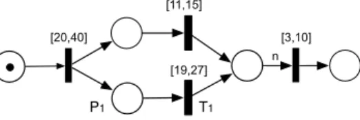
Firstly, the property-driven transformation from UML-MARTE to Time Petri Nets (TPN). This method translates semi-formal UML models into executable TPN models for verification purpose. TPN [13] is selected as the verification model, as it allows expressing and verifying time properties under both logi-cal and chronometric time models. This framework uses the TINA toolset [3] as model checker. Fig. 1 is a TPN example. Compared to Petri Nets, the transitions
[20,40] [3,10] n [11,15] [19,27] T1 P1
Figure 1. Time Petri Net Example
in TPN are extended with a time constraint that controls the firing time. For
example, transition T1is attached with time constraint [19,27]. When the token
arrives at place P1, the local timer of T1 starts. Between 19 and 27 time units,
T1can be fired. This transformation covers UML architecture models (using the
full Composite Structure Diagram) and behaviour models (using the full State Machine Diagram and a major subset of Activity Diagram). It is property-driven in order to limit the state space during model checking. Property-driven means that the transformation of some UML elements can be different depending on the assessed property; meanwhile the transformation does not conserve all the in-formation in UML, but only those concerning the property verification. Another
issue is raised from TPN theoretical limits. As model checking and reachability are undecidable in TPN when using stopwatch [4], the transformation method should avoid using stopwatches.
Secondly, the translation from time properties into time property patterns. Time properties are expressed using MARTE. These expressions cannot be di-rectly verified by TPN model checker. The proposed method translates them into a set of verifiable property patterns, which are quantitative. Their values can be computed in our proposal by iterative use of the model checker relying on dichotomy search. The time property patterns are independent of both the user modelling language and the verification language, making the method reusable in other verification frameworks. To make our method practical for end users, we focus on the time properties at both the event and the task levels. For the synchronization-related properties, we introduce the concept of time tolerance, because two simultaneous events cannot be measured without errors in the real world. The related work CCSL [2] focuses only on more symbolic time constraints at the event level without time tolerance.
Finally, the verification of time property patterns. The usual methods for verifying time properties in TPN rely mostly on LTL (Linear Time Logic), CTL (Computation Tree Logic) and µ-calculus. First, end users are not accustomed to their use. Second, these languages are not always powerful enough for some quantitative properties, in terms of both their semantic expressiveness and com-putation resource consummation. This issue is reduced by using the observer-based model checking. For one property pattern, an additional TPN structure extends the original TPN, then the reachability graph is generated using the highest abstraction. Complex LTL assertions become marking existence asser-tions, which can be cheaply computed. The observers do not change the original TPN’s behaviour. This observer-based verification method relying on TPN is independent of the user modelling language, making it reusable.
This paper is structured as follows: Section 2 compares this proposal with the related works; Section 3 briefly presents the verification framework for UML-MARTE; Section 4 introduces a representative case study; Section 5 presents the property-driven transformation method from UML-MARTE models to the target TPN models; Section 6 proposes the time property translation method and the time property patterns verification method based on observers in TPN; Section 7 evaluates the proposed framework by verifying the time property in the case study and analyses the method’s performance; Finally, comments on conclusion and further works are discussed in Section 8.
2
Related Works
Some works are also aimed to verify the properties in UML. The difference lies in the type of verification model and the capacity of the verification methods. Lilius and Paltor use the PROMELA language in [11] to specify UML models and ex-ploit the SPIN model checker. This method did not involve LTL verification and the author thought SPIN is not the most efficient solution. André and Mallet use
Esterel in [2] as verification language. Although its time constraint specification language CCSL covers logical and chronometric constraint in UML, its verifi-cation approach only supports logical constraints so far to our understanding. Gagnon et al. translate UML diagrams into Maude language and verify deadlock property using LTL in [6]. This work does not handle other time properties. In terms of performance, this work denotes that they still need to test this approach on larger examples. Knapp1 and Wuttke transform UML to a special class of timed automaton in [10], then translate them to concrete programs for model checkers SPIN. It verifies the consistency between different system descriptions. This work does not concern the time aspect. Medina and Cuesta present in [12] MARTE2MAST, a tool that enables the extraction of schedulability analysis models and their direct analysis using MAST [9]. It supports analysis by using simulation tool and static analysis techniques. It defines a complete package for system analysis including the scheduling algorithms. However, as the simulation is not exhaustive, it cannot prove the correctness in all possible cases. Shousha et al. describe in [16] a search-based UML-MARTE model analysis method for starvation and deadlock detection. It uses genetic algorithms to search through the state space. As the genetic search method cannot ensure the building of the full state space including all the final states, this method cannot guarantee that the whole space will be exhaustively searched. It can detect errors but cannot prove their absence, which is a significant drawback for safety critical systems.
Petri Nets are powerful models for describing system behaviour and for ver-ifying the properties. In [1] Andrade et al. map SysML Activity to ETPN (ex-tended TPN with energy constraints) to estimate the energy consumption and the execution time of system. Compared with this work, the advantages of our work lie in 3 aspects: for the time property scope, we verify a large scope of time properties, while [1] covers only the execution time; for the transformation method, we propose the property-driven transformation method and consider both the architecture and the behaviour models, while [1] only considers the behaviour model; for the verification method, we propose a novel observer-based TPN verification method.
3
Overview of UML-MARTE Verification Framework
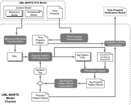
The objective of the UML-MARTE verification framework (Fig. 2) is to verify whether the design of UML-MARTE RTS Model satisfies the expected Time Property. The System Model consists of both Behaviour Model and Architec-tural Model. The former defines how the system will act and response to the outside world, while the latter describes the interconnection relation between sub-components of the system. In practice, the behaviour model is described by Activity and State Machine diagrams, and the architecture is defined by Composite Structure diagrams. All time related specifications and Time Prop-erties are modelled using MARTE profile. System Models are translated into TPN models through Behaviour/Structure Transformation. Time Properties are translated into Time Property Patterns by Time Property Transformation. All
the transformations are performed automatically and the formal activities are transparent to the end user. The model checking is performed on the generated Tag Pattern TPN models and the corresponding LTL/CTL/Marking Assertion by using TINA model checker. The verification is based on the observers added in the TPN. An observer is used to observe the value of one Property Pattern. Finally, Verification Result Computation is performed to combine the Property Pattern Results, then the target Time Property Verification Result is available.
TPN Tag Pattern TPN LTL/CTL!"#$%&'() *++,$-&.' TPN Model Checker Tag Property Pattern Result Behaviour/Structure Transformation Property Pattern TPN Generation Tag Property Pattern Result Interpretation Iteration Tag Preperty Pattern Result Time Property Transformation Time Property
Pattern Verification Result Computation Time Property Verification Result UML-MARTE Model Checker UML-MARTE RTS Model System Model Time Property Behaviour Model Architecture Model
Figure 2. UML-MARTE Model Checker
4
Case study
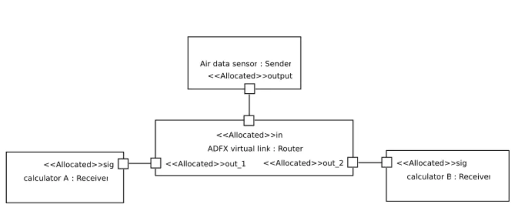
We use a classical asynchronous RTS model, IMA-based airborne system, to present the application of the proposed methods. According to the general asyn-chronous message-driven pattern, the sender will regularly distribute data to the two receivers through the communication networks that have transfer de-lays and jitters. The receivers will do some computation. Fig. 3 presents the architecture model. The sender represents a data-collecting sensor. The router represents a virtual link of Avionics Full DupleX (AFDX). The two receivers represent two identical calculators that provide redundant control. The input data of computation is sent by the sender through the router.
The elements from MARTE in Table 1 are used to describe time specification. The redundant controller design requires that the output of the two calculators must be available at the same time in each working cycle; otherwise, the servo
calculator A : Receiver <<Allocated>>sig
calculator B : Receiver <<Allocated>>sig ADFX virtual link : Router
<<Allocated>>in
<<Allocated>>out_1 <<Allocated>>out_2 Air data sensor : Sender
<<Allocated>>output
Figure 3. IMA-based Airborne Architecture Model
of the corresponding actuator cannot correctly unify the redundant command. In this case, we need to verify the coincidence of computation tasks between calculators A and B. As it is impossible to respect a strict simultaneous timing with an explicit local synchronisation, a time tolerance is defined. Once the two time instants fall into the same time window (size of window equals to tolerance), they are considered as coincident.
Table 1. MARTE Profile Usage
MARTE Profile Time Specification
GRM::ResourceUsage task’s execution time
GRM::CommunicationMedia communication delay
Alloc::Allocated mapping the soft data pin to the hard data port The AFDX only guarantees the communication delay upper bound, which means that the delay varies in [tmin, tmax]. Thus, it is obvious that the
compu-tation of calculators A and B are coincident only if the time tolerance is superior to (tmax− tmin), which is twice of the network jitter. In some cases, however, we
need to design some supplementary protocol between the receivers to decrease the coincidence time window in order to get better system robustness.
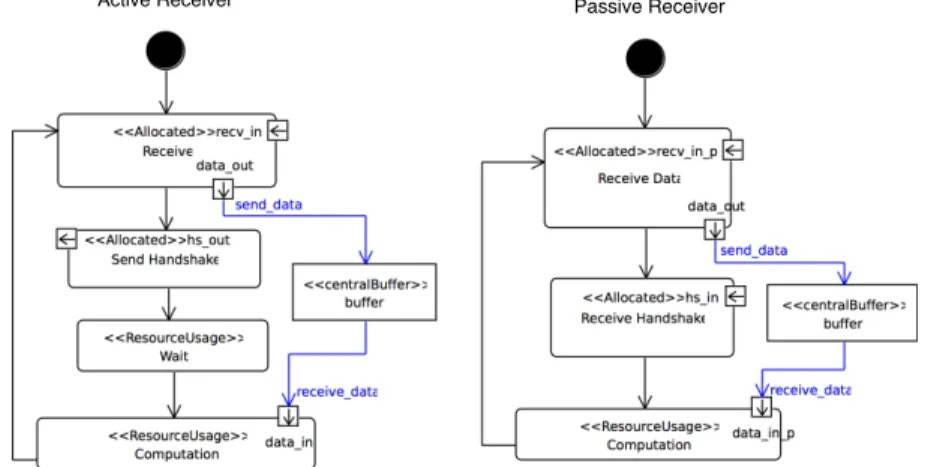
The designer implements a naive protocol relying on the hand shake paradigm of Fig. 4, in which the two receivers are distinguished by respectively setting as active and passive modes (Fig. 5). The active one, after getting the data from the sender, sends an asynchronous notification to the passive one and automati-cally waits for a fixed time duration to launch its computation. The passive one will start its redundant computation once it gets the notification from its active master. As the notification message is also passed by the same AFDX network, the designer could wonder if this protocol really solves the tolerance-reduction requirement. By modifying the wait time of the active receiver and the network jitter, the designer can use the proposed methods to verify whether the compu-tations are still coincident under the new protocol, and then refine his design according to the verification results. In this case study, we illustrate how our approach helps verifying time properties and assists the protocol designer with guaranteed correctness and performance.
calculator B : ActiveReceiver <<Allocated>>sig
<<Allocated>>handshake_out Air data sensor : Sender
<<Allocated>>output
calculator A : PassiveReceiver <<Allocated>>sig
<<Allocated>>handshake_in
AFDX virtual link : Router <<Allocated>>in
<<Allocated>>out_1 <<Allocated>>out_2
Figure 4. IMA-based Airborne System Architecture Model with Handshake Protocol
Active Receiver Passive Receiver
Figure 5. IMA-based Airborne System Behaviour Model with Handshake Protocol
5
Transformation from UML-MARTE to TPN
We present the principles of the UML transformation method and illustrate the transformation for a significant subset of UML elements of both the architecture and behaviour models. Due to page limits, the complete transformation rules for UML Activity Diagram can be consulted in [8]. The description of the UML State Machine Diagram transformation will be submitted later on.
5.1 Principles
The transformation approach is property-driven, aiming to limit the state space of model checking. The approach respects the following 6 principles:
1. The framework verifies each time property in one state space generation. This means one transformation keeps only the information for one property to be verified.
2. The transformation of one UML element may be different according to the time property.
3. For some UML elements not influencing time properties, the target TPN semantics can be standardized and homogeneous for all the properties. 4. The transformation should guarantee the consistency between high-level and
lower-level models. However, a correct transformation here does not imply a 100% semantic preservation, but rather to ensure the semantics necessary for the property verification are preserved through the transformation. 5. The target TPN models should ensure high performance verification,
espe-cially for large-scale asynchronous applications.
6. The patterns resulted from each element transformation should be easy to assemble. This may degrease the verification performance. But it can be com-pensated later by a model optimization phase that eliminates the elements irrelevant to the verification.
5.2 Architecture Model Transformation
The architecture parts in the model aim to connect the different parts to build a whole system, using communication media or shared resource. The transfor-mation method aims to replace each component of the architecture part by its relevant behaviour part, respecting a correct instance-mapping, context-based naming and their connection relationship. In the Composite Structure Diagram (CSD) from the case study, the significant elements are Part, Port and Connec-tor. The others remain important, but due to page limits, we only describe the mapping rules for Part and Port in this paper.
Part There are two patterns for Part : hierarchical and primitive (Fig. 6). The behaviour is described, for the former, by the Part’s inner structure, and, for the later, by the Part’s associated behaviour model. For the hierarchic pattern, the architecture model is considered as a tree-like structure, and the mapping approach is applied recursively.
No Explicit Inner Structure Port1 Port2 Primitive Hierarchic Port1 Figure 6. CSD-Part
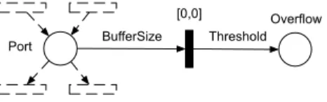
Port Port is used to connect outside structure and inner behaviour. MARTE Alloc::Allocated profile is used to map the logical PIN in behaviour model and the physical Port in architectural model. Port is transformed to an empty TPN place to represent a data buffer concept. In a bad designed system, data quantity may overfill the buffer size, it is thus important to detect this undesired property before doing the verification, as this may cause an undecidable boundedness problem in TPN verification. In order to avoid a non-terminating verification
problem, a supplementary structure is added (Fig. 7). It ensures that if the buffer is overfilled, it will raise an overflow. The overflow is represented by an ever-large marking that cannot exist in normal system. As TINA can detect on-the-fly any marking exceeding the pre-set threshold and stop state graph generation at once, this transformation method guarantees that all verification will finally terminate.
Port [0,0] BufferSize Overflow Threshold Figure 7. CSD-Port
5.3 Behaviour Model Transformation
A general transformation pattern is defined (see Fig. 8) to automate the assembly of the TPNs generated from the behaviour model. For all non-link elements in UML, the generated TPN must contain some C_IN transitions to connect with other predecessors in static model structure. In the same manner, some C_OUT places must exist to connect with its structural successors.
Transition-place structure
C_IN
C_OUT [0,0]
Figure 8. General Transformation Pattern
The main elements in the UML Activity Diagram (AD) are related to con-trol, action, resource, object, and connection. We present the transformation for OpaqueAction for system with single and multiple clocks (see later). An ac-tion is the fundamental unit of executable behaviour. It takes a set of inputs and converts them into a set of outputs. Depending on the abstraction level, an action could represent either a complex processing flow or a primitive one carrying out a computation. In UML-AD, there are 55 kinds of actions. Each kind covers a certain range of semantics for different usage. In order to focus on the core semantics related to time properties, we generalize the concept using the OpaqueAction.
Action Transformation Pattern The transformation method is illustrated by Fig. 9. All input data-related flows should link to B. All output data-related flows should link to C. All input resource-related flows should link to A. All
output resource-related flows should link to D. The execution time of one action is specified by the time constraint on transition C.
[0,0] [0,0] [0,0] C_IN C_OUT [0,0] [0,0] Casual ready Resource ready Input ready Output ready Resource released END A B C D [min,max]
Figure 9. UML Action Transformation to TPN
Mono-clock & Multi-clock In the real world, each clock has an independent drift. For systems with a single clock (mono-clock) this drift can be ignored, because the difference between tick duration and real physical time is of the same proportion at any given time for any part of the system. However, in systems with several clocks (multi-clock), the model transformation should be able to represent the correct time semantic of the system by considering the different clocks’ drifts. The solution is to assume a global physical clock and to project each time consumption and drift on this unique precise time reference. In our study, we use strictly the physical time notion as the exact reference for both mono and multi-clock base system.
Mono-Clock Action For mono-clock actions, the execution time is directly used after a global normalization of the time units. For example, if action A takes [3.4 ms, 4.7 ms] and actions B [78.9 us, 463.5 us], the correspondent min time and max time on the TPN transition is [34000, 47000] and [789, 4635] respectively, with the common unit of 0.1 us.
Multi-Clock Action For multi-clock actions, the execution time is specified by the expected physical time. Before integrating this time into a multi-clock based system, first we need to translate the expected physical time into tick numbers. Then its real physical time can be deduced by associating the clock’s drift. We use the same example as the previous one. Let clock A and B tick theoretically every 1 us, and their backward and forward drift are both 1%, therefore action A’s tick number is [3400, 4700] and B’s is [78.9, 463.5]. As tick number must be integer, a rounding strategy must be taken, without introducing unreasonable
conversion error. In our study, we use the floor function for tmin and ceiling
function for tmax. Therefore, we have A for [3400, 4700] and B for [78, 464] as
tick numbers after the rounding.
As the method assumes each component has independent clock, the drawback is that it can be too strict for those devices that share a clock. We still decide to
choose this abstraction paradigm, because in the verification viewpoint, this will only lead to a false-violation. It means that if a time property is satisfied under independent-clock hypothesis, it must be also satisfied in a shared-clock system. This sufficient but not necessary condition may only cause a performance trade-off in practice, but never gives out a wrong verification result when property’s proof is positive.
6
Translation and Verification of Time Property
The time properties should be translated into TPN-compatible analyzable for-malism. In our case study, the property is the coincidence between two tasks. We illustrate the property translation and verification methods for this property. The translation for all the synchronization-related properties can be consulted in [7]. The verification of other properties will be presented in other papers.
6.1 Translation of Coincidence Property
Definition (Task Level Coincidence). Task X and Y are coincident if f. the
nthoccurrence of X occurs simultaneously with the nth
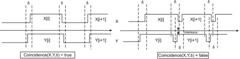
occurrence of Y , n ∈ N. X[i] X[i+1] Y[i] Y[i+1] ! ! ! Coincidence(X,Y,!) = true X Y X[i] X[i+1] ! ! ! ! ! Interleave Coincidence(X,Y,!) = false Y[i] Y[i+1]
Figure 10. Coincidence Property
As shown in Fig. 10, the coincidence between two tasks is determinated by
the coincidence between the Eventstart and the Eventend of tasks. For the nth
occurrence of task X and Y, if the two Eventstart are coincident and the two
Eventend are coincident within time tolerant δ, task X and Y are coincident.
Formally, task coincidence is translated into the following 3 equivalent assertions. Coincidence(X, Y, δ) ≡ ∀t ∈ R+: (|O(Xst) − O(Y t s)| < 2) ∧ (|O(X t e) − O(Y t e)| < 2) (1) ∀t ∈ R+: (|T (Xst) − T (Y t s)| < δ) ∧ (|T (X t e) − T (Y t e)| < δ) (2)
∀i ∈ N∗: (T (Xei) + δ < T (Ysi+1)) ∧ (T (Yei) + δ < T (Xsi+1)) (3)
In the above assertions, X represents task; Xa the inner event a of task
inner event of task X; Xt
a the occurrence of Xa which is the nearest (forward or
backward) to the time instant t; T (Xi
a) the occurring time instant of Xai; T (Xat)
the occurring time instant of Xt
a; O(Xat) the occurrence count for Xa at time t;
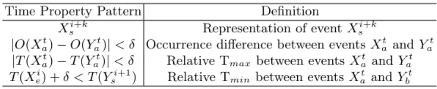
and δ is the time tolerance for coincidence. There are 4 time property patterns in the assertions (Table 2). The task-level property is then represented by a set of event-level property patterns.
Table 2. Time Property Patterns
Time Property Pattern Definition
Xsi+k Representation of event Xsi+k
|O(Xt
a) − O(Yat)| < δ Occurrence difference between events Xat and Yat
|T (Xt
a) − T (Yat)| < δ Relative Tmax between events Xat and Yat
T (Xi
e) + δ < T (Ysi+1) Relative Tminbetween events Xat and Ybt
6.2 Verification of Time Property Pattern |T (at) − T (bt)| < δ
To assess the time property, the observer pattern is added into the original TPN, and then the TINA model checker is used to verify the observer-dedicated LTL/CTL/Marking assertions for the TPN. As model checking significantly con-sumes time and memory resource, we use the following 2 approaches to ensure the verification performance.
– When doing the model checking, the TPN shall perform the highest possible abstraction to unfold the reachability graph. This high abstraction model should preserve the desired time property. The model-checking is on-the-fly. – Each assertion’s verification is independent in terms of reachability graph
generation, so a parallel computation is possible.
We choose one of the property patterns, |T (at) − T (bt)| < δ, to illustrate the
verification method. The principle of deciding whether two events are always occurring in a given bound is to find out whether one could advance another by time δ.
An observer pattern (Fig. 11) is added in the original TPN. The middle transition will always instantly neutralize the tokens from the places Occ A and Occ B except when one token waits for a time longer than δ that leads to the firing of Pass transition. To guarantee the termination of model checking, the pattern is extended by adding a large overflow number on the tester’s incoming arc. We use places tester A and tester B to detect this exception. In the generated reachability graph, it only requires to verify if tester A or tester B has marking.
The assertion is:♦(testerA = 1) ∨ ♦(testerB = 1)
Once it is known how to verify |T (at) − T (bt)| < δ, it is possible to change
δ to compute a near optimal tolerance. If |T (at) − T (bt)| < δ + 1 is verified as
true, but false for |T (at) − T (bt)| < δ, then the near optimal tolerance is δ + 1.
In order to improve the computation efficiency, a dichotomy search is used to reduce the complexity from O (N ) to O (log N ).
Event A tester A overflow [δ,δ] Observer Event B tester B [δ,δ] overflow [0,0] Occ A Occ B Pass A Pass B
Figure 11. |T (at) − T (bt)| < δ Pattern TPN Observer
7
Verification Result and Performance Analysis
7.1 Verification Result 600 700 800 900 1000 1100 1200 1300 1400 1500 1600 1700 1800 1900 2000 2100 2200 2300 2400 2500 1100 1200 1300 1400 1500 1600 1700 1800 1900 2000 2100
tolerance with protocol (ms)
wait time (ms)
Figure 12. Verification Result: Best Wait Time of Active Receiver
In the case study, the designer aims to design a protocol relying on our verification framework, and then evaluate the system performance. The designer alters the wait time of the active receiver and the jitter, selects the network average delay and computes the coincidence tolerance. The result is shown in Fig. 12. Different coloured lines represent the result with different jitters. The variation is regular and linear because the modelled system is conceptually simple without resource sharing. It is obvious that the best wait time of the protocol is 1600ms.
Then the user aims to evaluate this protocol by verifying the coincidence property. In the verification result (see Table 3), comparing the minimum
co-incidence tolerance in original system and that in the protocol system, it is obvious that the protocol succeeds in decreasing the tolerance value. We can say the system is more robust than the original.
Table 3. Verification Result: Independence with Designed Hand shake Protocol (ms)
Network Average Delay Network Jitter Time Window Min Coincidence tolerance Original System Protocol System
1600 100 200 685 617 1600 300 600 1085 817 1600 500 1000 1485 1017 1600 700 1400 1885 1217 1600 900 1800 2285 1417 1600 1100 2200 2685 1617 1600 1300 2600 3085 1817 1600 1500 3000 3485 2017
7.2 Verification Performance Analysis
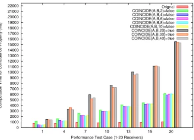
The performance of model checking is a very important issue for the end user. In this verification framework, we have used property-driven transformation, observer-based verification in highest abstraction mode and parallel computation methods to avoid the explosion of state space problem and to ensure a high performance. To validate the performance, we focus on two aspects: efficiency and scalability. The objective is to find out that within an acceptable time range for rapid system prototyping (less than 1 minute), the framework is able to verify the coincidence property of system with a scale of 2 senders, 2 routers, and 1-20 pairs of active-passive receivers which is representative of current avionics systems. 0 1000 2000 3000 4000 5000 6000 7000 8000 9000 10000 11000 12000 13000 14000 15000 16000 17000 18000 19000 20000 21000 22000 1 4 7 10 13 15 20
Computation Time for Coincidence Property (ms)
Performance Test Case (1-20 Receivers)
Orignal COINCIDE(A,B,2)=false COINCIDE(A,B,4)=false COINCIDE(A,B,6)=false COINCIDE(A,B,8)=false COINCIDE(A,B,10)=false COINCIDE(A,B,20)=true COINCIDE(A,B,30)=true COINCIDE(A,B,40)=true
The performance evaluation result (Fig. 13) shows both the efficiency and the scalability of the performance. The efficiency is shown by the verification’s computation time. For a system with 20 pairs of receivers, the original reach-ability graph generation time is less than 1000ms on a common computer; the computation time proving that the property is true is less than 16000ms, and the computation time proving that the property is false is about 6000ms. It is straightforward that proving a property false needs less time than the truth proof, because once a violation is detected the checking terminates. The scalabil-ity is shown by the linear relation between the time-over-cost of verification and the system’s scale. When the increasing ratio is constant, it guarantees that if the original system reachability graph could be generated, then all the verifications of its time properties using our framework will take an appropriate time.
8
Conclusion and Further Works
In this paper, we propose a time property verification framework for UML-MARTE safety critical RTS. This verification framework can assess time prop-erties like upper bound for loops and buffers, B/WCRT, B/WCET, B/WCTT, schedulability and synchronization-related properties (synchronization, coinci-dence, exclusion, prececoinci-dence, sub-occurrence, causality). In addition, it can ver-ify some behavioural properties like the absence of deadlock or dead branches. We evaluate the framework with a representative case study focusing on the property of coincidence between two tasks. The verification result demonstrates this framework can not only verify the time properties, but also assist the sys-tem’s design at early phases of the lifecycle. The performance test and analysis illustrate the efficiency and scalability of the framework. Due to page limits, we will present the other properties’ verification in other contributions.
One contribution is the proposition of the property-driven transformation, time property translation and observer-based verification methods. The time property translation method is independent of both the design modelling lan-guage and the verification lanlan-guage; the observer-based verification method is independent of the design modelling language. This independence allows these methods to be integrated in other verification frameworks. Another contribution is the approaches for reducing the state space combinatorial explosion problem, including the property-driven transformation, the highest abstraction on-the-fly model checking, and the parallel computation.
In the future, we will focus on extending this framework. On the technical side, we will optimize the TPN models by finding some reducible structural patterns without influencing the property. On the methodological side, we will experiment with other kind of properties, like the functional property, to improve the Property-driven approach to DSML (Domain Specific Modelling Language) model verification that started in the TOPCASED project.
References
1. Andrade, E., Maciel, P., Callou, G., Nogueira, B.: A methodology for mapping sysml activity diagram to time petri net for requirement validation of embedded real-time systems with energy constraints. In: Digital Society, 2009. ICDS ’09. 2. André, C., Mallet, F.: Specification and verification of time requirements with ccsl
and esterel. In: Proceedings of the 2009 ACM SIGPLAN/SIGBED conference on Languages, compilers, and tools for embedded systems. pp. 167–176. LCTES ’09, ACM, New York, NY, USA (2009)
3. Berthomieu, B., Ribet, P.O., Vernadat, F.: The tool tina - construction of abstract state spaces for petri nets and time petri nets. International Journal of Production Research 42(14), 2741–2756 (2004)
4. Berthomieu, B., Lime, D., Roux, O., Vernadat, F.: Reachability problems and abstract state spaces for time petri nets with stopwatches. Discrete Event Dynamic Systems 17, 133–158 (2007)
5. Combemale, B., Crégut, X., Garoche, P.L., Thirioux, X., Vernadat, F.: A property-driven approach to formal verification of process models. In: Cardoso, J., Cordeiro, J., Filipe, J., Pedrosa, V. (eds.) Enterprise Information System IX, vol. 12, pp. 286–300. LNBIP, Springer (2008)
6. Gagnon, P., Mokhati, F., Badri, M.: Applying model checking to concurrent uml models. Journal of Object Technology 7(1), 59–84 (Jan 2008)
7. Ge, N., Pantel, M.: Verification of synchronization-related properties for uml-marte rtes models with a set of time constraints dedicated formal semantic http://hal. archives-ouvertes.fr/hal-00677925
8. Ge, N., Pantel, M., Crégut, X.: Time properties dedicated transformation from uml-marte activity to time petri net (August 2012), http://hal.archives-ouvertes. fr/hal-00686986, submitted to 5th International workshop UML and Formal Methods (UML&FM’2012)
9. Gonzalez Harbour, M., Gutierrez Garcia, J., Palencia Gutierrez, J., Drake Moyano, J.: Mast: Modeling and analysis suite for real time applications. In: Real-Time Systems, 13th Euromicro Conference, 2001.
10. Knapp, A., Wuttke, J.: Model checking of uml 2.0 interactions. In: Proceedings of the 2006 international conference on Models in software engineering. pp. 42–51. MoDELS’06, Springer-Verlag (2006)
11. Lilius, J., Paltor, I.: vuml: a tool for verifying uml models. In: Automated Software Engineering, 1999. 14th IEEE International Conference on. pp. 255 –258 (oct 1999) 12. Medina, J.L., Cuesta, A.G.: From composable design models to schedulability anal-ysis with uml and the uml profile for marte. SIGBED Rev. 8(1), 64–68 (Mar 2011) 13. Merlin, P., Farber, D.: Recoverability of communication protocols–implications of a theoretical study. Communications, IEEE Transactions on 24(9), 1036 – 1043 (sep 1976)
14. Object Management Group, Inc.: OMG Unified Modeling LanguageTM, Super-structure (Feb 2009)
15. Object Management Group, Inc.: UML profile for MARTE: modeling and analysis of real-time embedded systems version 1.0 (Nov 2009)
16. Shousha, M., Briand, L., Labiche, Y.: A uml/marte model analysis method for uncovering scenarios leading to starvation and deadlocks in concurrent systems. Software Engineering, IEEE Transactions on PP(99), 1 (2010)