HAL Id: hal-01592858
https://hal.univ-lorraine.fr/hal-01592858
Submitted on 25 Sep 2017
HAL is a multi-disciplinary open access
archive for the deposit and dissemination of
sci-entific research documents, whether they are
pub-lished or not. The documents may come from
teaching and research institutions in France or
abroad, or from public or private research centers.
L’archive ouverte pluridisciplinaire HAL, est
destinée au dépôt et à la diffusion de documents
scientifiques de niveau recherche, publiés ou non,
émanant des établissements d’enseignement et de
recherche français ou étrangers, des laboratoires
publics ou privés.
Technology Platform ENERBAT -Gas Cogeneration,
Solar Heating and Cooling
Riad Benelmir, N Ghilen, M Ganaoui, D Descieux, S Gabsi
To cite this version:
Riad Benelmir, N Ghilen, M Ganaoui, D Descieux, S Gabsi. Technology Platform ENERBAT
-Gas Cogeneration, Solar Heating and Cooling. International journal of thermal and environmental
engineering, International Association for Sharing Knowledge and Sustainability, 2014, 7, pp.79 - 85.
�10.5383/ijtee.07.02.004�. �hal-01592858�
*
Corresponding author. Tel.: +34977 559665
Fax: +34977 559691; E-mail:[email protected]
© 2014 International Association for Sharing Knowledge and Sustainability DOI: 10.5383/ijtee.07.02.004
Technology Platform ENERBAT - Gas Cogeneration,
Solar Heating and Cooling
R. Benelmir*, N. Ghilen, M. El Ganaoui, D. Descieux and S. Gabsi
Faculty of Sciences and Technology Lab. LERMAB (UdL/INRA/Labex ARBRE) University of Lorraine, France
Abstract
Energy cogeneration is a way to improve global efficiency of energy production systems since it consumes a unique resource in order to supply heat and electrical power through optimal use of heat fluxes associated to power production. Energy trigeneration enlarges the concept to the production of cold also. It consumes a unique resource to produce electricity, heat and cold. Nevertheless, we could go more ahead by substituting a part of the primary fuel resource by renewable energy as solar energy in order to reduce the carbon impact. This is conducted through the use of adsorption refrigeration which needs hot water to produce cold water. However, even if energy utilities are provided with the best efficient way, the final use of energy could make all the efforts fall. Cooling ceilings present one of the best solutions to be coupled to solar cooling since it needs a medium range cold temperature of the fluid in order to avoid condensation if the wall ceiling temperature drops below the ambient air dew point temperature. All these constraints need to be checked experimentally and confronted to numerical simulation. For this purpose, an experimental platform has been developed combining an internal combustion gas engine (cogenerator), a refrigerating adsorption machine, thermal solar collectors and wooden construction split in two compartment, a cold one conditioned by cooling ceilings and a hot one conditioned by heating floors. The platform is completely instrumented. In this paper we focus only on the refrigeration machine for which we developed a simulation model that is confronted to experimental measurements.
Keywords:tri-generation, solar cooling, adsorption machine
1. Introduction
During the last decades, sorption refrigeration systems had considerable craze due to the necessity of replacing energy consuming and harmful classic systems to the environment [1]. The field of application of this type of refrigeration is large (domestic, commercial and medical refrigeration, food-processing industry).
Solar refrigeration by adsorption was studied since the sixties [2], but it is only towards the end of the seventieth that interest for this process increased and gave birth to prototypes using the performances of various couples: activated carbon-methanol [3-4], zeolite-water [5-6 ], activated carbon-ammonia [7-8], silica gel-water [9-11]. Indeed, silica gel-water presents the advantage of excellent physical and thermal properties of water (high latent heat of evaporation, high thermal conductivity, low viscosity, thermal stability in a wide range of operating
temperature and a compatibility with several materials) as well as good adsorption property of silica gel (high adsorption/desorption rate and low generation temperature). The couple of silica gel-water can be classified as the best couple for adsorption refrigeration applications [12].
In our platform, the solar adsorption refrigerator uses a silica gel-water couple in the following operating nominal conditions: inlet temperature at condenser/adsorber about 24°C, inlet temperature at desorber about 61°C and inlet temperature at the evaporator about 14°C.
2. The adsorption phenomena
The adsorption process during which the molecules of a fluid called adsorbate or refrigerant, settle on the surface of a solid matter called adsorbent. The surface of the solid corresponds to the external surfaces engendered by the network of pores and cavities inside the adsorbent. There are two types of
Benelmir et al. / Int. J. of Thermal & Environmental Engineering, 7 (2014) 79-85
adsorptions, chemical or physical, according to the nature of the binding of the molecules of gas and the energies involved. In the chemical adsorption, the binding of the molecules of adsorbate on the surface is made by strong chemical connections where the energy of connection is rather high (50 to 400 kJ/mol), while the physical adsorption process results from lower physical connections, with energies of interaction of the order of 20 kJ/mol. This binding of the molecules of the fluid on the surface of the solid is essentially made by means of Van der Waals forces. Hence, the physical adsorption is perfectly reversible: the adsorbed molecules can be easily desorbed after an increase of the temperature.
From the thermodynamics point of view, physical adsorption is considered as a fluid process from gaseous phase to an adsorbed phase. This transformation is conducted at constant temperature and pressure.
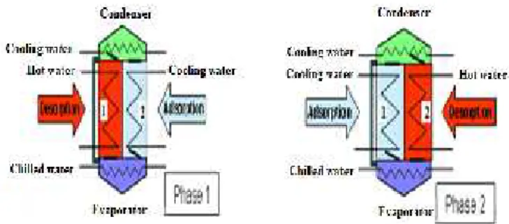
3. Sorption refrigerating machine with two beds of adsorbents
The machine with double adsorbents beds includes two compartments filled with adsorbent, an evaporator and a condenser.
The adsorbent of the compartment 1 is regenerated by heating (solar hot water), the desorbed water vapor flows towards the condenser where it condenses. The water condensate flows to the evaporator via an expansion valve where it evaporates (cold production).
The adsorbent of the compartment 2 maintains the low pressure by adsorbing this water vapor. This compartment must be cooled in order to maintain the process of adsorption. When the cold production decreases (saturation of the adsorbent), the functions of the compartments are switched (Figure 1).
Figure 1 Sorption refrigerating machine operating principle
4. Experimental Results
We analyzed the evolution of the inlet/outlet/mean temperatures at the heat exchangers (evaporator, condenser and generator) and within the storage stratification tank as well as the heat fluxes and coefficient of performance (COP).
The operating conditions of the adsorption machine (manufacturer: Sortech) are:
- Turn on temperature threshold: 75°C < TG,i < 94°C - Non operating temperatures: TG,i > 94 °C & TG,i < 60°C
Temperatures at the stratification tank
Figure 2 presents the variation of the temperatures with respect to time for a period of 24 hours (starting from midnight) at four levels of the stratification tank (Tb1, Tb2, Tb3, Tb4).
We observe that:
- The stratification is marked ;
- The temperature threshold allowing the start-up of the adsorption machine is 75°C and occurs in the middle of day at 13:00 (780 mn) ;
- The temperature decreases with time due to the withdrawal of hot water for the cold production (adsorption machine).
- The temperature threshold allowing the shutdown of the adsorption machine is 60°C and occurs at the end of the afternoon at 16:00 (970 mn).
- The operation mode of the adsorption machine lasted about 3 hours (190mn)
-Figure 2 Evolution of the temperatures at four levels of the stratification tank
Inlet/outlet temperatures of the circuits
Figure 3 presents the variation of the inlet/outlet temperatures of each circuit of the refrigeration machine (generator’s heat supply circuit, condenser’s heat withdrawal circuit and evaporator’s cold production circuit).
Following this graph:
- The inlet temperature to the generator has a monotonous evolution while the other temperatures are fluctuating periodically with a specific cycle. Indeed, all temperatures depend on the adsorption/desorption cycle except the inlet temperature of the generator which is related to the upper level of the stratification tank.
- The cycle duration at the beginning of operation of the refrigeration machine (804-852 mn) is about 48 mn. This cycle becomes shorter after the stabilization of the operation of the machine. In fact, at the beginning of operation, the valves are all opened and both beds desorb and adsorb at the same time.
- During the rest of the time the cycle duration is about 15 mn.
- In a cycle, for a period of 7mn, the inlet hot water temperature (To_Gn) gets closer to the outlet hot water temperature, thus the heat consumed by the desorption at this stage is rather low.
- During the operation of the machine, a temperature variation (inlet/outlet) of the fluid of 2, 2.9 and 3°C is observed respectively for the generator, condenser and evaporator.
Figure 3 Evolution of the inlet/outlet temperatures of each circuit
Temperatures at the generator, condenser and evaporator
Figure 4 shows the evolution of the desorption, condensation and evaporation experimental temperatures which were derived by means of the following relation:
)
exp(
, , pw w in j out jc
m
UA
T
T
T
T
(1) We notice that:- The desorption temperature varies between 64°C and 55 °C.
- The refrigerant condenses at a temperature between 31.5°C and 29.5 °C (condensation pressure: 4,2kPa). - The evaporation of water occurs between 11.5°C and
12.5°C (low evaporation pressure : 1,22kPa)
Figure 4 Evolution of the desorption, condensing and evaporation temperatures
Generator heat supply
The instantaneous power is calculated by the following relation:
)
(
, , . gn out gn in p gnm
c
T
T
P
(2))
(
, , . cd out cd in p cdm
c
T
T
P
(3))
(
, , . ev out ev in p evm
c
T
T
P
(4)According to Figure 5 we have a chequered evolution of the power within a specific cycle. The average thermal power is about 20 kW for desorption, 22 kW for condensation and 6 kW for evaporation (cooling).
Figure 5 Heat supply power, condenser heat dissipation and evaporator cooling load
Temporal Evolution of coefficient of performance of machine has adsorption
In order to estimate the performance of the adsorption machine we evaluate the coefficient of performance (COP) in heating and cooling mode:
gn ev cooling
P
P
COP
(5) gn cd heatingP
P
COP
(6)Benelmir et al. / Int. J. of Thermal & Environmental Engineering, 7 (2014) 79-85
We have an average performance coefficient of 0.7 in cooling mode and of 1.7 in heating mode.
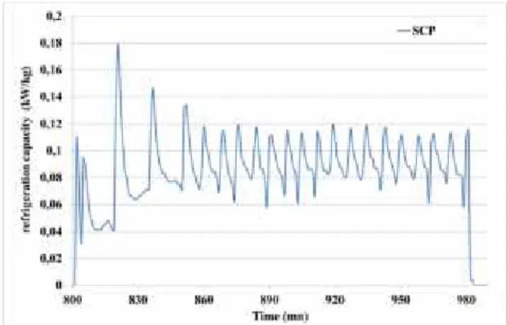
Refrigeration capacity
The refrigeration capacity is calculated by the following relation: a ev
m
P
SCP
(W/kgsilica gel) (7)According to Figure 6, the refrigeration capacity is about 90 W/kg (of silica gel).
Figure 7 SCP of the refrigeration adsorption machine
Cumulated energy histogram
Figure 8 presents the variation of the energy accumulated at the generator (2.7 kWh), the condenser (1.8 kWh) and the evaporator (0.8 kWh).
Figure 8 Cumulated energy
5. Numerical Model of the refrigeration adsorption machine
The model is based on one hand on energy balance and on the other hand on the kinetics of adsorption for the various constituents of the machine. The operating principle of the refrigeration adsorption with two compartments is already available in the literature [13-16]. In this study we are interested by two-bed adsorption refrigeration with a tubular heat exchanger coated with silica gel. Heat exchanger surface
is pasted by means of epoxy resin (figure 9), which has the following advantages [17]:
-Improved heat transfer rate. -Improved vapor transport rate. -Less volume and weight.
Figure 9 Adsorber design
The parameters used in the numerical model are presented in
Error! Reference source not found.. The main assumptions
are as follows:
- Uniform temperature and pressure in the adsorber - No heat losses (thermal insulation of the machine)
[13,14]
Table 1 Parameters used in the model
Parameter Value 50 kg 2800 kJ/kg 2500 kJ/kg 24.28 kg 12.45 kg 0.386 kJ/kg.K 1.85 kJ/kg.K 0.905 kJ/kg.K 0.924 kJ/kg.K 4.18 kJ/kg.k 10 kg 3420 W/K 6090 W/K 3570 W/K 3290 W/K 64.04 kg 1.6 m3/h 3.7 m3/h 2 m3/h 14,3°C 24 °C 61 °C
Isotherm of adsorption
The concentration of adsorbate (water) in the adsorbent (silica gel) at thermodynamic equilibrium is calculated by using the equation developed by Boelman [18].
6 . 1 1 *
)
)
(
)
(
(
s s w sT
P
T
P
w
SCP
(kgwater/kgsilica gel) (8) Where Ps(Tw)and Ps(Ts) are the pressure of saturated vapor at respectively the refrigerant (water) temperature and adsorbent (silica gel) temperature, the adsorption data obey the Freundlich equation. Ps is estimated through the following equation [13]: 470937 . 0 ) 15 . 273 ( 0857427 . 0 ) 15 . 273 ( 2 0013802 . 0 ) 15 . 273 ( 3 0000888 . 0 T T T Ps (9) Kinetics of adsorptionIn this model, the rate of adsorption or desorption is governed by the LDF equation [16] (eq.10-12). The coefficients of the equation of LDF (Linear Driving Force) for silica gel/water were determined by Chihara and Suzuki [19] (
Table2).
)
*
(
w
w
av
k s
dt
dw
(kg/kg.s) (10)R p
Ds
F
av
k s
0
2
(s-1) (11)e
Ea
RT
Ds
Ds
0
(m²/s) (12) Table 2 Coefficients of the LDF equationCoefficient Value
2.54 E-4
1.7 E-4 m 4.2 E4 J/mol 15
Energy balance at the adsorbent beds
The energy balance for the adsorbent bed is given by:
) ( . ) ( ) 1 ( ) ( , , T T mw T T dt dw c pwv ma dt dw H ma dt dT c pw w ma dt dT ca ma cal mhex out j in j pw ev ads
c
(13)Where =0 during the transient valves switching phase and =1 during the adsorption or desorption cycle. The subscript “j” refers to either the heating or cooling fluid depending on the adsorption or desorption mode of the concerned compartment. In this case, =0 if the concerned compartment is operating as an adsorber and =1 if the concerned compartment is operating as a desorber.
The outlet temperature of the heating water is calculated by the mean logarithmic temperature difference:
)
exp(
, , pw w in j out jc
m
UA
T
T
T
T
(14)Energy balance at the condenser
The energy balance at the condenser is as follows:
) ( . ) ( , , T T mcw L dt w d ma T T dt w d c pwv w ma dt T d ccu M cd out cd in cd pw des cd des cd
c
(15)Energy balance at the evaporator
The energy balance at the evaporator can be expressed as:
) ( . ) ( ) ) ( ( , , T T mchw T T c pw dt w d ma L dt w d ma dt T d c pw t M ccu M ev out ch in ch pw ev cd des ads ev w
c
(16) with:dwdes
ma
wads
ma
M w
t
M w
(
)
0
(17)The refrigerated capacity of the system is defined by:
t
T
T
c
cycle out ch in ch pwt
mchw
Qev
cycle
0(
, ,)
.
.
(18)and the heating power is:
t
T
T
c
cycle out h in h pwt
mhw
Qh
cycle
0(
, ,)
.
.
(19)Benelmir et al. / Int. J. of Thermal & Environmental Engineering, 7 (2014) 79-85
.
.
Qh
Qe
COP
(20) 6. Numerical resultsFigure 10 illustrates the evolutions of the water outlet temperatures at the adsorbent beds. The numerical results correlate well with the experimental temperature of water leaving the generator.
The sequence of two sorption cycles is clear on these curves: - Phase I: adsorption in bed#2 / desorption in bed#1 - Phase II: adsorption in bed#1 / desorption in bed#2
Figure 10 Temperatures profiles at the adsorbers, condenser, and evaporator (experimental and numerical)
Figure 11 presents the variation of the saturated water vapor pressure in the adsorbers, condenser, and evaporator. The condensation pressure varies between 5 and 7 kPa which corresponds to a condensation temperature in the range 35 to 40°C. The evaporation pressure is about 1 kPa which corresponds to an evaporation temperature of the order of 10°C.
Between these two pressures are situated both intermediate phases of heating (pressurization) and cooling (depressurization).
Figure 11 Pressure dynamic behavior at the adsorbers, condenser, and evaporator (numerical values)
On figures 10 and 11, on could notice the relative accurate representation by the model of the behavior of the machine with respect to pressure and temperature.
Figure 12 illustrates the variation of thermal power at the generator, condenser and evaporator with respect to time which are in concordance with experimental results.
The coefficient of performance is about 0.65, which is interesting for a free renewable energy resource’s cold production system.
Figure 12 Thermal power dynamic behavior at the adsorbers, condenser, and evaporator (numerical values)
Figure 13 presents the variation of the adsorbed mass in each adsorbing bed with respect to time. The average adsorbed or desorbed mass is about 16,5g for 1kg of silica gel.
Figure 13 Adsorbed mass of water at the adsorbers (numerical values)
7. Conclusions
The technology platform ENERBAT provided experimental measurements allowing the tuning of a simulation model for the operation of an adsorption refrigeration machine. This double bed solar refrigeration machine has the advantage of total autonomy and continuity in cold production. The model is global and allows following the variation of the physical parameters as the temperature and pressure in every component of the machine as well as the mass of water vapor adsorbed during the cold production. The COP is fair since the energy
source (solar) is free. The numerical results from this model correlated well with experimental measurements.
Benelmir et al. / Int. J. of Thermal & Environmental Engineering, 7 (2014) 79-85
Nomenclature
A [m2] Heat transfer area Cp [kJ/kgK] Specific heat
COP [-] Coefficient of Performance
L [kJ/kg] Latent heat of vaporization
M,m [kg] Mass
t
[kg/s] [s]
Mass flow rate Time
T [K] Temperature
∆Hads [kJ/kg] Isosteric heat of adsorption
P U Q w w* [kpa] [kW/Km2] [kW] [kW] [kg/kg] [kg/kg] Pressure
Overall heat transfer coefficient Heat transfer Power Instantaneous mass Equilibrium mass Rp R SCP Ds0 Ea [m] [J/kgK] [kW/kg] [m2/s] [J/kg]
Adsorbent particles radius Gas constant
Specific cooling power Surface diffusion Activation energy Subscripts a Adsorbent ad Adsorber ads Adsorption Al Aluminum cd Condenser
ccw Condenser Cooling water Chw cu cw cycle des ev g gn hw in l out w wv Chilled water Copper Cooling water Cycle Desorption Evaporator Gas Generator Hot water Inlet liquid Outlet Water Water vapor References
[1] D.D. Riffel, U. Wittstadt, E. P. Schmidt, Transient modeling of an adsorber using finned-tube heat exchanger, International Journal of Heat and Mass Transfer, 53. 2010 1473–82.
[2] R. Plank, J. Kuprianoff, In Die Kleinkaltemaschine, Springer-Verlag, Berlin, 1960.
[3] M. Pons, Ph. Grenier, Experimental data on a solar powered ice maker using activated carbon and methanol adsorption pair, Journal of Solar Energy Engineering, 109. 1987, pp. 303-310. [4] F. Mhiri, S. El Golli, Etude d’un réfrigérateur solaire à adsorption
solide avec le couple charbon actif méthanol, Rev. Gén. Therm, 35, 1996, pp. 269-277.
[5] J. Guilleminot, F. Meunier, Etude expérimentale d’une glacière
solaire utilisant le cycle zéolithe 13X-eau, Rev.Gen.Therm, 239. 1981, pp. 825-834.
[6] J. Schwarz, DieAdsoptionskaltemaschine mit dem Stoffpaar Zeolith/wasser, die kalte und klimatechnik, 9.1990, pp. 492-505. [7] R.E. Critoph, An Ammonia Carbon Solar Refrigerator for
vaccine cooling, Renewable Energy, 5. 1994, pp. 502-508. [8] L.L. Vasiliev, D.A. Mishkinis, A.A. Antukh, Jr. L.L. Vasiliev,
Solar-Gas Solid Sorption Refrigerator, Adsorption, 7. 2001, pp. 149-161.
[9] F. Bucher, C. Hildbrand, Ph. Dind, M. Pons, Experimental data on an advanced solar-powered adsorption refrigerator. Heat Powered 01, Internationnal conference, 2001, pp. 61-68. [10] I.I. El-Sharkawy, H. AbdelMeguid, B.B. Saha, Towards an
optimal performance of adsorption chillers: Reallocation of adsorption/desorption cycle times, International Journal of Heat and Mass Transfer, 63. 2013,pp. 171–182
[11] R.M. Rezk, Raya K. Al-Dadah, Physical and operating conditions effects on silica gel/water adsorption chiller performance, Applied Energy, 89. 2012, pp.142–149.
[12] R. K. Aldadah, ARM. Rezk, Empirical simulation model of silica gel/water adsorption chiller, ASME-ATI-UIT, thermal and environmental issues in energy systems, Sorrento, Italy. 2010. [13] Wang, D.C., et al. Study of a novel silica gel–water adsorption
chiller. Part I. Design and performance prediction. International Journal of Refrigeration. 2005, Vol. 28, pp. 1073–1083
[14] Chuaa, H.T., et al. Modeling the performance of two-bed, sillica gel-water adsorption chillers. International Journal of Refrigeration. 1999, 22, pp. 194–204
[15] Wang, Xiaolin and Chua, H.T. Two bed silica gelewater adsorption chillers: An effectual lumped parameter model. International Journal of Refrigeration. 2007, Vol. 30, pp. 1417-1426
[16] Saha, B. B., et al. ‘Study on an activated carbon fiber ethanol adsorption chiller: Part I- system description and modelling. International Journal of Refrigeration. 2007, Vol. 30, pp. 86 – 95 [17] Dr. Jorg Rupp. Solar cooling for small scale application with
adsorption technology, Sortech AG, Germany. 2009, pp. 2. [18] Boelman, E.C., Saha, B.B. and Kashiwagi, T. Computer
simulation of a silica gel–water adsorption refrigeration cycle— the influence of operating conditions of cooling output and COP. ASHARE Transactions. 1995, pp. 348–355
[19] Chihara K, Suzuki M. Air drying by pressure swing adsorption. Journal Of Chemical Engineering Of Japan. 1983, Vol. 16, 4, pp. 293–299.