HAL Id: hal-01516633
https://hal.archives-ouvertes.fr/hal-01516633
Submitted on 2 May 2017HAL is a multi-disciplinary open access archive for the deposit and dissemination of sci-entific research documents, whether they are pub-lished or not. The documents may come from teaching and research institutions in France or abroad, or from public or private research centers.
L’archive ouverte pluridisciplinaire HAL, est destinée au dépôt et à la diffusion de documents scientifiques de niveau recherche, publiés ou non, émanant des établissements d’enseignement et de recherche français ou étrangers, des laboratoires publics ou privés.
Public Domain
A new numerical approach to simulate rolling processes
of thin sheet using Asymptotic Numerical Method and
Arlequin Method
Kékéli Kpogan, Hamid Zahrouni, Michel Potier-Ferry, Hachmi Ben Dhia
To cite this version:
Kékéli Kpogan, Hamid Zahrouni, Michel Potier-Ferry, Hachmi Ben Dhia. A new numerical approach to simulate rolling processes of thin sheet using Asymptotic Numerical Method and Arlequin Method. 12e Colloque national en calcul des structures, CSMA, May 2015, Giens, France. �hal-01516633�
CSMA 2015
12 Colloque National en Calcul des Structures 18-22 Mai 2015, Presqu'île de Giens (Var)
A new numerical approach to simulate rolling processes of thin sheet
using Asymptotic Numerical Method and Arlequin Method
K. Kpogan 1, H. Zahrouni 1, M. Potier-ferry 1 H. Ben Dhia 2
1
LEM3, DAMAS, Université de Lorraine, {kekeli.kpogan, hamid.zahrouni, michel.potier-ferry}@univ-lorraine.fr 2
MSSMat, Ecole Centrale de Paris, [email protected]
Abstract —In this paper we present a new numerical technique to model the buckling phenomena
under residual stresses induced by rolling process. This technique consists in coupling two finite element models: the first one consists in a three dimensional model which is used to model the three dimensional behaviour of the sheet in the roll bite; the second model is based on a shell formulation well adapted to large displacements and rotations, it will be used to compute buckling of the strip out of the roll bite. We propose to couple these two models by using Arlequin method.
Mots clés — Rolling, Buckling, Arlequin Method, Asymptotic Numerical Method
1. Introduction
Flatness defects are among the major problems encountered in strip rolling. Their direct origin is out-of-bite stress gradients resulting in buckling in the compressive stress areas. The most important flatness defects are “edge-waves” and “center-waves” buckles. These waves are the result of buckling due to self-equilibrating longitudinal residual stresses with a compressive longitudinal membrane force state in the middle of the strip (“center buckles”) or in the edge zones (“edge buckles”), respectively. During the rolling process, the buckling waves are usually suppressed by global traction. Thus, in some cases, the sheet may appear more or less flat, or even perfectly flat on the rolling line. Nevertheless we can still talk about flatness defects, insofar as there may be residual stresses in the sheet. This is why the post-bite stress profile is called “latent flatness defects”. If defects are only latent, the stress field computed beyond the bite by a 3D finite element model (FEM) should be correct. One can find in the literature three ways to model rolling, depending on the manner to account for flatness defects. The first way is based on 3D FEM that generally does not permit to capture buckling effects; they can only predict latent defects. Other models permit to account for buckling in an uncoupled approach: the 3D model yields residual stresses that are further included as the starting part of a buckling analysis. Last, few FEM are able to model rolling and buckling in a coupled manner.
Several publications have been focused on uncoupled approaches. Counhaye [3] was the first to propose a coupling model of rolling process and buckling phenomena. The model is based on a stress– relaxation algorithm applied only in the out-of-bite areas. They added an additional term to the elastic/plastic strain rate decomposition which represents the local shortening of a material segment when it becomes wavy due to buckling. This model is limited to represent buckling modes. Abdelkhalek et al. [4] used a different approach for coupling 3D FEM and Asymptotic Numerical Method (ANM) using a shell formulation. In this approach, a full 3D model of rolling is computed; the post-bite stress field obtained is introduced in the shell formulation where a buckling analysis under residual stresses is performed. The new distribution of the stress field obtained by buckling is considered as a new boundary condition for the 3D FEM. These computations are repeated until
In the present work, we propose a new approach to simulate rolling process taking into account buckling phenomena. A simplified model is used which consists in coupling a 3D continuum model and a shell model using Arlequin method. The buckling is due to residual stresses which are introduced in the 3D model and propagated in the shell model during the simulation.
2. Formulations
In this section, we propose to give details of the formulations of the mechanical problems. The challenge is to have a reference code taking into account the rolling conditions (rolling forces and friction, rolls bending…) and the buckling phenomena of the strip out of the roll bite. In this work, we start from the general formulation of rolling processes and subsequently propose a new simplified approach to get close to the real conditions of rolling and bring us solutions to the limitations of existing models.
We denote the study domain Ω; ∂Ω is the border of Ω including a contact surface ∂Ωc with the work rolls and a surface ∂Ωf where are imposed normal and tangential stresses. The resolution of the general problem consists in determining solution of the following variational formulation:
For all v* kinematically admissible:
c c f * * * imp * t nv : D d
v dS
nv dS
T
v dS
where D* is the virtual strain-rate tensor which derives from the virtual velocity field v*. We designate σt and σn respectively, the shear stress caused by the friction and the pressure exerted by the working
rolls on the sheet in the contact area. We note Timp the external stress vector imposed on the sheet (upstream and downstream tractions rolling). This general formulation uses elastoplastic law.
The general formulation and the behavior law so described are implemented in the code LAM3 [6]. It presents satisfactory results for cases whose flatness defects do not occur. However for the case of rolling we are studying, the sheets are likely to buckle under the effect of residual stress, which involves taking into account the bifurcation analysis and the bending behavior of the sheet. LAM3’s results for these test cases proved limited in representing flatness defects. This limitation is mainly due to the use of hexahedral elements for the space discretization of the finite element model. Thus, to simulate the buckling phenomena it takes considerable degrees of freedom including several discretization elements in the sheet thickness; which requires large computation time and makes the simulation of the process almost impossible for industrial needs.
We therefore propose to keep the 3D elements to study the behavior of the sheet in the roll bite and to couple them with shell elements to study the buckling phenomena in the downstream domain. Buckling phenomena are the consequence of residual stresses that are derived from LAM3 code. In upstream domain, we assume that the sheet arrives without deformation. So, we propose an algorithm which consists in coupling 3D FEM and shell model by Arlequin method. So the idea is to combine these two models in the same finite element simulation that we solve by ANM.
In the three dimensional part, we consider small strain and residual stresses which come from a full model taking into account the elastoplastic law adapted to rolling. We use small strain in this part of the model since we assume that the sheet in upstream of the roll mill is flat. But progressively, the 3D model will transmit the residual stresses to the shell model.
In the shell part, we consider a geometrically nonlinear model. This shell model, proposed by Büchter el al. [5], avoids locking by incorporating an additional parameter describing the shell thickness variation. It is distinguished from classical shell models that are usually based on
degenerated constitutive relations, since the present formulation uses the unmodified and complete three-dimensional constitutive law.
3. Arlequin coupling
The Arlequin method allows to couple two different mechanical states through reliable coupling operators as well as consistent energy distribution between the two coupling zones .
The central point of the model is the coupling operator which is selected by analogy with the deformation energy of the shell. Otherwise the coupling area varies during the rolling process. In this paper, we limit ourselves to the H1coupling, and hence
,
.
( ) :
:
( )
l l
c
u
u
D
u d
We denote respectively
u
andµ
the displacement and the Lagrange multiplier fields;γ
lis the linear part of the total Green-Lagrange strain tensor;D is the elasticity tensor. The Arlequin method uses alot of ingredients that request to be explained. One can see details in [1].
4. Asymptotic Numerical Method
ANM is a technique for solving nonlinear equations based on the Taylor expansion to high order [2]. The technique consists in transforming a given nonlinear problem into a sequence of linear ones to be solved successively, leading to a numerical representation of the solution in the form of power series truncated at relatively high orders. Compared to iterative methods, ANM allows significant reduction of computation time since only one decomposition of the stiffness matrix is used to describe a large part of the solution branch. Thus, the procedure allows developing the unknown variables of the problem in the form of power series with respect to a path parameter "a" (see [2] for more details).
5. Results
The presented test case concerns flatness defects generated by a rolling industrial process. The procedure we proposed is non-iterative coupling: (i) first a rolling calculation (LAM3) allows us to provide residual stresses, (ii) to compute flatness defects, a second calculation using the coupling code 3D/shell/Arlequin is then performed considering residual stresses resulting from the previous calculation. The results are compared with Counhaye’s [3] and Abdelkhalek’s [4] models and with experimental measurements. Note that Counhaye’s model is a modification of rolling code LAM3 which only relax membrane stresses in compression zones but the model is limited for the representation of flatness defects in the sheet. Moreover, the procedure proposed by Abdelkhalek is based on an iterative coupling between the rolling code LAM3 and a thin shell code. It is also able to relax the excessive stresses and predicts flatness defects of various shapes. But compared to our new procedure, it has some limitations. Firstly, it’s too complicated; the first iteration is a complete rolling calculation, the following describes only the downstream domain of the structure. Secondly, the transfer of the data between subdomains is not really standard. In particular, clamped boundary condition which is used on the shell model side of the bite is not very convincing.
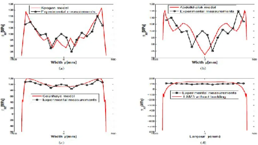
Let us call the method proposed in this work, Kpogan’s model. Figure (1) illustrates
σ
xx profiles forKpogan, Abdlekhalek and Counhaye’s models. We notice that with Kpogan’s model (figure 1a), the stresses are relaxed and they are close to the experimental measurements. Compared to the results of Abelkhalek (figure 1b) and Counhaye’s (figure 1c) models, Kpogan’s model (figure 1a) gives results much closer to the experiment.
Figure 1 – Comparisons of results with reference models ; Figure (a) : : Kpogan’s model; Figure (b) : Abdelkhalek’s model ; Figure (c) : Counhaye’s model ; Figure (c) : LAM3 code without buckling
5. Conclusion
We have proposed in this study a numerical model which consists in coupling Arlequin and asymptotic numerical methods to simulate flatness defects observed in rolling process. Our attention was focused on very thin sheets where these phenomena are often observed. Note that in thin sheet rolling, we need tri-dimensional model to compute correctly the deformations in the bite and a shell model far from the rolls to compute buckling modes. It is not obvious for a unique model to capture all these phenomena. Both models are coupled by using Arlequin method. This method allows us to model the entire structure while distinguishing upstream and downstream domain of the sheet. We performed an industrial rolling test case taking into account complex residual stresses obtained by the rolling code LAM3. The results were compared with experimental data. The model we proposed gives satisfactory results. It predicts the relaxed stresses after buckling and shows the corresponding flatness defects.
Références
[1] H. Ben Dhia, Multiscale mechanical problems : the Arlequin method, Comptes Rendus de l’Académie des Sciences,Serie IIb,Paris, 899-904, 1998.
[2] B. Cochelin, N. Damil, and M. Potier-Ferry, Méthode Asymptotique Numérique: une technique de résolution des équations non linéaires, Hermes Science Publishing, Paris, Londres, 2007.
[3] C. Counhaye, Modélisation et contrôle industriel de la géométrie des aciers laminés à froid (modelling and industrial control of the geometry of cold rolled steels), PhD thesis, University of Liege, 2000.
[4] S. Abdelkhalek, H. Zahrouni, M. Potier-Ferry, N. Legrand, P. Monmitonnet, P. Buessler, Coupled and uncoupled approaches for thin cold strip buckling prediction, International journal of material forming, 833-836, 2009.
[5] N. Büchter, E. Ramm, D. Roehl, Three-dimensional extension of non-linear shell formulation based on the enhanced assumed strain concept, International journal for numerical methods in engineering , 2551–2568, 1994.
[6] A. Hacquin, P. Montmitonnet, P. Guillerault, A steady state thermo-elastoviscoplastic finite element model of rolling with coupled thermo-elastic roll deformation, Journal of materials processing technology, 109– 116, 1996.