HAL Id: hal-01202020
https://hal.sorbonne-universite.fr/hal-01202020
Submitted on 18 Sep 2015
HAL is a multi-disciplinary open access
archive for the deposit and dissemination of
sci-entific research documents, whether they are
pub-lished or not. The documents may come from
teaching and research institutions in France or
abroad, or from public or private research centers.
L’archive ouverte pluridisciplinaire HAL, est
destinée au dépôt et à la diffusion de documents
scientifiques de niveau recherche, publiés ou non,
émanant des établissements d’enseignement et de
recherche français ou étrangers, des laboratoires
publics ou privés.
On-body propagation characterization with an H-plane
Substrate Integrated Waveguide (SIW) horn antenna at
60 GHz
Solofo Razafimahatratra, Julien Sarrazin, Theodoros Mavridis, Luca Petrillo,
Philippe de Doncker, Carole Leduc, Maxim Zhadobov, Ronan Sauleau, Aziz
Benlarbi-Delai
To cite this version:
Solofo Razafimahatratra, Julien Sarrazin, Theodoros Mavridis, Luca Petrillo, Philippe de Doncker, et
al.. On-body propagation characterization with an H-plane Substrate Integrated Waveguide (SIW)
horn antenna at 60 GHz. Conference EuMW 2015, Sep 2015, Paris (Palais des Congrès), France.
�hal-01202020�
On-body propagation characterization with an H-
plane Substrate Integrated Waveguide (SIW) horn
antenna at 60 GHz
Solofo Razafimahatratra, Julien
Sarrazin, Aziz Benlarbi-Delaï
Laboratoire d’Electronique et Electromagnétisme
Sorbonne Universités, UPMC Univ Paris 06, UR2, L2E, F-75005
Paris, France
solofo.razafimahatratra1@etu.upmc.fr, julien.sarrazin@upmc.fr, aziz.benlarbi_delai@upmc.fr
Theodoros Mavridis, Luca Petrillo,
Philippe De Doncker
Wireless Comm Group - OPERA Dpt.Université libre de Bruxelles Bruxelles, Belgique
tmavridi@ulb.ac.be,lpetrillo@ulb.ac.be, pdedonck@ulb.ac.be
Carole Leduc, Maxim Zhadobov,
Ronan Sauleau
Institute of Electronics and Telecommunications of Rennes University of Rennes 1 Rennes, France carole.leduc@univ-rennes1.fr, maxim.zhadobov@univ-rennes1.fr, ronan.sauleau@univ-rennes1.fr
Abstract—A planar end-fire H-plane Substrate Integrated
Waveguide (SIW) horn antenna is designed for 60 GHz on-body channel measurements. The proposed antenna radiates with a polarization normal to the human skin, and yet exhibits a low profile. Furthermore, a 6.1 GHz bandwidth (S11 < -10dB) is
achieved, which enables wide-band channel characterization. The antenna has been fabricated and its performance is evaluated in the presence of a skin-equivalent phantom. Its suitability to perform on-body channel measurements is then discussed.
Keywords—SIW horn antenna; millimeter wave; Body Area Network; on-body propagation; Norton formulation
I. INTRODUCTION
Compared to lower frequency band, 60 GHz is attractive for Body Area Networks (BANs) applications for component compactness, large available bandwidth, and low human body skin penetration. Besides, its high atmospheric attenuation provides high level of security, safety and low interference with other networks [1] [2]. That is why there has been a growing interest recently in the use of 60 GHz for BAN. However, as it is well known, millimeter wave frequencies suffer from a severe link budget, especially in Non-Line-Of-Sight (NLOS) situations that are often encountered in on-body communications. Thus, channel measurements have been recently conducted to assess 60 GHz suitability for BAN applications. Deterministic models have been developed [3, 4], as well as stochastic models [5-7], which take into account the human mobility. However, to author’s best knowledge, no wideband channel model is yet available to describe BAN behavior over the whole license-free 60 GHz bandwidth (from 57 GHz to 64 GHz).
To establish such a wideband channel model, realistic measurement will require low profile antenna in order to describe the channel behavior very close to the skin surface, where surface waves may exist. Furthermore, these low-profile
antennas will need to operate over 7 GHz at 60 GHz, which represents a bandwidth of approximately 11.7%. In the literature, a planar monopole [8] and a Yagi antenna [9] have been identified as potential candidates that can achieve these requirements. However, both radiate electric field that is tangentially polarized to the human body. It has been proved in [1] that the normal to the body surface polarization suffers less from absorption losses than tangential polarization thus enhancing the link budget.
Consequently, this paper focuses on the design of a large-band planar antenna, able to cover the 11.7% large-bandwidth at 60 GHz while radiating a normal to the body surface polarized electric field. The design is presented in section II while its performance in terms of radiation is discussed in section III. The suitability of this antenna for on-body wireless link characterization is then investigated in section IV using analytical models and measurements. Finally, a conclusion is drawn in section V and perspectives are given.
II. ANTENNA DESIGN
A SIW horn antenna has been designed with RT Duroid 5880 substrate (εr = 2.2, tanδ = 0.003) with a thickness of
0.787 mm. The spacing between vias and the vias diameter are defined with respect to the rules in [10]. The calculated spacing is 0.12 mm for a via diameter of 0.12 mm. However, the spacing between vias is set to 0.16 mm because of fabrication constraints. As a result, part of the energy leaks through the via array-based walls but overall performance is not disturbed.
The SIW horn antenna exhibits a narrow band of 2.8% and a gain of 4.57 dB with an efficiency of 83.6%. To increase the achieved bandwidth, horn’s size could be increased. However, for horn’s width exceeding 7.5 mm, it has been shown in [11] that higher modes appear. This is not desired since it leads to multiple radiation main beams. Consequently, metallic plates
are added to the output of the horn as suggested in [12], as illustrated in Fig. 1. These resonating strips enable to increase the bandwidth up to 10.5%, without deteriorating the end-fire gain (5.08 dB) and the efficiency (89.5%). The simulated S11
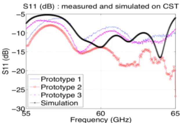
is given in Fig. 3 and it can be seen that a -10 dB impedance matching is achieved from 58.3 GHz up to 64.4 GHz, which almost cover the targeted license-free 60 GHz bandwidth.
The antenna is matched to a 50 Ω coaxial connector through a microstrip taper transition. The taper dimensions have been optimized through numerical optimization. The final design of the antenna with V connector is presented in Fig. 2.
The reflection coefficients obtained in both simulation and measurements are shown in Fig. 3. The simulation includes the coaxial connector and has been conducted with CST Microwave Studio. Measurement results are given for two prototypes. The obtained 10 dB bandwidth is 6 GHz in simulation and more than 7.7 GHz in measurement. The discrepancy between the results is essentially due to the etching tolerance, which is mainly critical on the two resonating strips’ length. Furthermore, the coaxial connector is assembled with the antenna board with two screws. Depending on the applied screw pressure, obtained results are also different.
Fig. 1. SIW horn antenna design on CST : profile view.
Fig. 2. Realized antennas : top and bottom view.
III. RADIATION PERFORMANCE
A. In free space
The radiation pattern is presented in Fig. 4 and Fig. 5 for the H-plane and the E-plane respectively. The simulated gain is 6.6 dB in the end-fire direction. The observed ripples are essentially due to surface waves guided by the substrate that are mainly excited at the microstrip to SIW-waveguide transition.
Fig. 3. Return loss S11 (dB) : simulation on CST and measurement.
The ripples and the dissymmetry observed in the E-plane are mainly due to the reflection occurring on the coaxial connector. The Front To Back Ratio (FTBR) is about 12 dB.
Fig. 4. Radiation pattern in free space : H plane.
Fig. 5. Radiation pattern : E plane.
B. On-body
The human body influence on the radiation patterns is to be analyzed. The human body is emulated by a phantom, whose electrical properties represent the human skin (εr =
7.98, σ = 36.4 S/m), as given in [13]. The phantom is 2 mm thick and is homogenous since 2 mm is much larger than the skin depth at 60 GHz (less than 0.5 mm). The antenna is centered on the phantom of size 100 x 124 mm2 with an open
space around. Parallel plates y x y z x z y y x y x
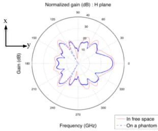
When lying the antenna down on the surface of the phantom, its radiation characteristics are given in Fig 6. (H plane: parallel to the phantom plane) and Fig. 7 (E plane: normal to the phantom surface). In Fig. 7, the end-fire gain is decreased down from 6.6 dB to 5.34 dB compared to the free space case. While the H-plane pattern is not much affected by the phantom, the E-plane appears to be more affected and lobes are tilted. This is due to reflections occurring at the air/phantom interface as already observed in [14].
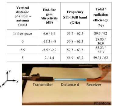
Without connector, the end-fire gain of the antenna on the phantom’s surface is only -12dB. Study of the influence of the vertical distance between the phantom and the antenna is summarized in table I. The horn SIW antenna without connector has been simulated with CST Microwave Studio for three different vertical distances. It can be observed that the higher the vertical distance, the higher the end-fire gain since free space condition is approached. The antenna radiation gets partly absorbed by the phantom, an effect that increases when the antenna gets closer to the phantom. It has to be emphasized that the given efficiency is only valid for the considered phantom’s size. However, it is interesting to note that for a distance between the antenna and the skin of a half-wavelength, the efficiency is almost doubled compare to the case where the antenna lies on the skin surface.
IV. LINK CHARACTERIZATION
The SIW horn antenna is used as transmitter for on-body link characterization. The receiver is an open-ended waveguide (cf. Fig. 8).
A. Norton theory
Norton defines field equations on a dielectric surface characterized by its permittivity and conductivity [15]. From these equations, we can distinguish three types of wave: direct wave, reflected wave, and surface wave.
This theory is applied to a dipole placed on the previously mentioned phantom characteristics and at a transmitter height of 6 mm above the phantom.
B. Measurement settings
For the measurement, the transmitter is fixed first at a vertical distance hT = 4 mm from the phantom’s surface and then at hT = 10 mm. hT corresponds to the vertical distance between the phantom’s surface and the bottom of the horn antenna. For each transmitter position, the receiver is moved along the line of sight at a distance d (50 mm to 250 mm) and along the z-axis at a height h (0 mm to 10 mm) as shown in Fig. 8.
C. Analytical results for a dipole and measurement comparison
The measurement is compared to dipole radiation path loss. The normalized path loss variation along the distance transmitter – receiver d is presented in Fig. 9. The field amplitude level according to Norton formulation and the measured S21 decrease with the same exponent on the body in the observed distance.
When the antenna is placed at 10 mm higher above the phantom, the attenuation is reduced from 22.5 dB to 19.9 across the same distance.
Fig. 10 shows the received field dependency on the receiver height h at a fixed distance d of 250 mm. There is little difference between the two transmitter heights. Simulated and measured results are in good agreement. The received field intensity is higher away from the surface. There is an approximately 10 dB difference between the field on the surface and 10 cm above. This is due to the fact that the so-called Norton surface wave, which is mostly bounded to the interface, is actually in phase opposition with the sky wave contribution. Thus, away from the skin, the Norton wave contribution becomes negligible and the total field results only from the direct and reflected waves (i.e. sky wave contribution), which are almost in phase.
Fig. 6. Radiation pattern – phantom influence : H plane.
Fig. 7. Radiation pattern – phantom influence : E plane.
V. CONCLUSION AND FUTURE WORK
In this study, a 60-GHz horn antenna was designed, characterized and realized. The planar antenna dimension is 17 x 24 x 0.787 mm3. This antenna is compatible with BAN applications. The radiation is directive with a 6.6 dB end-fire gain. y x y z
TABLE I. ANTENNA PERFORMANCES FOR DIFFEERENT VERTICAL (AIR)
DISTANCE BETWEEN PHANTOM AND ANTENNA Vertical distance phantom - antenna (mm) End-fire gain /directivity (dB) Frequency S11-10dB band (GHz) Total / radiation efficiency (%) In free space 6.6 / 6.9 56.7 – 62.5 89.5 / 92 0 -13.3 / -8 50.8 – 63.3 28.85 / 30.9 2.5 -5.5 / -2.7 57.5 – 63.5 55.23 / 57.3 5 2 / 4.4 56.9 – 63.2 59.31 / 62
Fig. 8. Link characterization : SIW horn antenna to a waveguide.
Fig. 9. Normalized path loss – dependance on the horizontal distance d.
Fig. 10. Normalized path loss – dependance on the receiver height h.
Antenna properties are assessed on the body using a equivalent phantom in an on-body propagation scenario. The analytical results and measurements at 60 GHz up to a distance of 250 mm between the horn antenna and a waveguide are coherent. The attenuation on the body is 22.5 dB for a distance of 200 mm. The total wave is more reflected than directed along the antenna surface. For the two transmitter antenna heights, a little difference of the tilt angle due to the phantom reflection is observed. The shape and the movement of the body have to be integrated for a full study.
ACKNOWLEDGMENT
This work was performed within the Labex SMART supported by French state funds managed by the ANR within the Investissements d'Avenir programme under reference ANR-11-IDEX-0004-02.
REFERENCES
[1] P. S. Hall, Y. Hao, S. L. Cotton, “Progress in antennas and propagation for body area networks”, IEEE Signals Systems and Electronics (ISSSE), International Symposium, Vol. 1, pp. 1-7, September 2010. [2] L. Petrillo, T. Mavridis, J. Sarrazin, D. Lautru, A. Benlarbi-Delaï, P. De
Doncker, “Analytical Creeping Wave Model at 60 GHz for On-Body Communications “, 7th European Conference on Antennas and Propagation, November 2013.
[3] L. Petrillo, T. Mavridis, J. Sarrazin, D. Lautru, A. Benlarbi-Delaï, P. De Doncker, “Analytical Creeping Wave Model and measurements for 60 GHz Body Area Networks”, IEEE Trans. on Ant. and Propa., Vol. 62, no. 8, 2014, pp. 4352-4356.
[4] N. Chahat et al., “On-body propagation at 60 GHz”, IEEE Trans. on Ant. and Propa., Vol. 61, 2013, pp. 1876–1888.
[5] L. Petrillo, T. Mavridis, J. Sarrazin, A. Benlarbi-Delaï, P. De Doncker, “Statistical On-Body Measurement Results at 60 GHz”, IEEE Trans. on Ant. and Propa., Vol. 63, no. 1, 2015, pp. 400-403.
[6] C. Constantinou, Y. Nechayev, W. Xianyue, P.S. Hall, "Body-area propagation at 60 GHz", Loughborough Antennas and Propagation Conference (LAPC), 12-13, November 2012.
[7] Y.I. Nechayev, W. Xianyue, C. Constantinou, P.S. Hall, "Millimetre-wave path-loss variability between two body-mounted monopole antennas", IET Microwaves Antennas & Propagation, vol.7, no.1, 2013 [8] J. Hautcoeur, L. Talbi, K. Hettak, “Monopole Lozange antenna for 60-GHz applications “, IEEE Antennas and Propagation Society International Symposium (APSURSI), 2012, pp. 1-2.
[9] N. Chauhat, M. Zhadobov, L. Le Coq, R. Sauleau, “Wearable end-fire textile antenna for on-body communications at 60 GHz “, IEEE Antennas Wireless Propagation Letters, Vol. 11, 2012, p. 799-802. [10] D. Deslandes and K. Wu, “Integrated microstrip and rectangular
waveguide in planar form”, IEEE Microwave Wireless Components Letters, Vol. 11, n°2, 2001, pp. 68-70.
[11] S. Razafimahatratra, J. Sarrazin, A. Benlarbi Delaï, P. De Doncker, “ Horn antenna design for BAN millimeter wave on-body communication “, IEEE APS, pp. 204-2, July 2014.
[12] M. Esquius-Morote, B. Fuchs, J-F. Zürcher and J. R. Mosig, “A Printed Transition for Matching Improvement of SIW Horn Antennas”, IEEE Transactions on Antennas and propagation, Vol. 61, n°4, Aprill 2013. [13] P. A. Hasgall et al., ITIS Database for Thermal and Electromagnetic,
Parameters of Biological Tissues, Version 2.2, www.itis.ethz.ch/database, July 2012.
[14] M. Zhadobov et al., “Millimeter-wave interactions with the human body: state of knowledge and recent advances”, International Journal of Microwave and Wireless Technologies, vol. 3, no 02, 2011, p. 237-247. [15] R. W. P. King, G. J. Fikioris, R. B. Mack, “Cylindrical antennas and
arrays”, Cambridge University Press, 2002.
y z x