Cryogenic sample exchange NMR probe for magic
angle spinning dynamic nuclear polarization
The MIT Faculty has made this article openly available.
Please share
how this access benefits you. Your story matters.
Citation
Barnes, Alexander B., Melody L. Mak-Jurkauskas, Yoh Matsuki,
Vikram S. Bajaj, Patrick C.A. van der Wel, Ronald DeRocher, Jeffrey
Bryant, et al. “Cryogenic sample exchange NMR probe for magic
angle spinning dynamic nuclear polarization.” Journal of Magnetic
Resonance 198, no. 2 (June 2009): 261-270.
As Published
http://dx.doi.org/10.1016/j.jmr.2009.03.003
Publisher
Elsevier
Version
Author's final manuscript
Citable link
http://hdl.handle.net/1721.1/82050
Terms of Use
Creative Commons Attribution-Noncommercial-Share Alike 3.0
Cryogenic sample exchange NMR probe for magic angle spinning
dynamic nuclear polarization
Alexander B. Barnesa, Melody L. Mak-Jurkauskasa,b, Yoh Matsukia,b, Vikram S. Bajaja, Patrick C. A. van der Wela, Ronald DeRochera, Jeffrey Bryanta, Jagadishwar R. Sirigiric, Richard J. Temkinc, Johan Lugtenburgd, Judith Herzfeldb, and Robert G. Griffina,*
aDepartment of Chemistry and Francis Bitter Magnet Laboratory, Massachusetts Institute of
Technology, Cambridge, MA 02139, USA bDepartment of Chemistry, Brandeis University, Waltham,
MA 02454, USA cPlasma Science and Fusion Center, Massachusetts Institute of Technology,
Cambridge, MA 02139, USA dDepartment of Chemistry, Rijksuniversiteit te Leiden, NL-2300 R A
Leiden, The Netherlands
Abstract
We describe a cryogenic sample exchange system that dramatically improves the efficiency of magic angle spinning (MAS) dynamic nuclear polarization (DNP) experiments by reducing the time required to change samples and by improving long-term instrument stability. Changing samples in conventional cryogenic MAS DNP/NMR experiments involves warming the probe to room temperature, detaching all cryogenic, RF, and microwave connections, removing the probe from the magnet, replacing the sample, and reversing all the previous steps, with the entire cycle requiring a few hours. The sample exchange system described here — which relies on an eject pipe attached to the front of the MAS stator and a vacuum jacketed dewar with a bellowed hole — circumvents these procedures. To demonstrate the excellent sensitivity, resolution, and stability achieved with this quadruple resonance sample exchange probe, we have performed high precision distance measurements on the active site of the membrane protein bacteriorhodopsin. We also include a spectrum of the tripeptide N-f-MLF-OH at 100 K which shows 30 Hz linewidths.
Keywords
Dynamic Nuclear Polarization; Instrumentation; Hardware; Cryogenic MAS
1. Introduction
Dynamic nuclear polarization (DNP) increases the sensitivity of NMR by transferring the large spin polarization from stable paramagnetic centers to the nuclear spin reservoir [1;2]. In recent applications to biological solids, the enhanced polarization is generated by millimeter wave irradiation of the EPR transitions of biradical polarizing agents [3] and is uniformly dispersed to the system of interest via proton spin diffusion [4;5]. During the polarization process, spin lattice relaxation mechanisms compete with the polarization growth in the proton bath. These
* Corresponding author. Fax: 1-617-253-5405, E-mail address: [email protected].
Publisher's Disclaimer: This is a PDF file of an unedited manuscript that has been accepted for publication. As a service to our customers
we are providing this early version of the manuscript. The manuscript will undergo copyediting, typesetting, and review of the resulting
NIH Public Access
Author Manuscript
J Magn Reson. Author manuscript; available in PMC 2010 October 19.
NIH-PA Author Manuscript
NIH-PA Author Manuscript
T1 processes are slower at lower temperatures and cryogenic operation (presently around 85
K) permits the polarization from the electrons to effectively complete a relayed transfer to such systems as membrane or amyloid proteins [6;7] and peptide/protein nanocrystals [8]. In addition, in the temperature regime discussed here, the spin polarization is proportional to the inverse of the sample temperature; thus, at 85 K the polarization is another factor of
approximately three larger than at room temperature.
However, conventional low temperature magic angle spinning (MAS) NMR experiments generally suffer from poor experimental efficiency due to the time required to change samples. In particular, the simple task of switching from a standard sample used to adjust B0
homogeneity, the magic angle, etc. to the sample of interest involves warming the probe to room temperature, detaching all cryogenic, radiofrequency (RF), and microwave connections, removing the probe from the magnet, and replacing the sample. Subsequently, the procedure is reversed, with the entire warming-cooling cycle requiring a few hours. This process also increases mechanical wear and the risk of damage to the microwave waveguide and mirror system that delivers the millimeter wave radiation to the sample.
The sample exchange system described here permits the sample to be changed in a matter of minutes without disturbing the probe. It is driven by N2 and consists of a custom designed eject
pipe attached to the front of a Revolution NMR (Ft. Collins, CO) MAS stator that mates with a bellowed hole in a vacuum jacketed dewar. Thus, the rotor is ejected through the top of the dewar into a vacuum jacketed transfer tube running through the magnet bore. A teflon tube on top of the magnet is used to slow and receive the sample. The quadruple resonance
(1H, 13C, 15N and e-) MAS probe described here is a fourth generation design, and the system (probe plus sample eject) has been operating routinely for over a year and has dramatically increased the efficiency of our experiments. It is used routinely with an existing 380 MHz / 250 GHz DNP spectrometer described elsewhere [9;10].
This paper is divided into two sections. First, we describe the overall system architecture and the instrumentation required for achieving and maintaining cryogenic sample temperatures while thermally isolating the probe tuning elements. This includes a detailed description of the design of the cryogenic sample exchange system. The instrumentation section closes with a description of the quadruple resonance RF/microwave circuit based on the Schaefer-McKay air dielectric transmission line design.
In Section 3 we demonstrate the capabilities of the system by providing illustrative examples, which include a demonstration of a stable DNP enhancement over multiple sample exchanges, a spectrum showing the exquisite resolution achievable for a peptide at cryogenic temperature, and a precise distance measurement between two selectively-labelled 13C sites in the membrane protein bacteriorhodopsin.
2. Instrumentation
2.1. System architectureFig. 1 shows an overview of the system architecture used for cryogenic DNP/NMR. The major components consist of (left to right in the figure) the N2 control system, the heat exchanger,
the quadruple resonance MAS probe and finally (moving vertically) the sample chamber and eject pipe, the eject tube, and the receiving and inserting chambers.
For cryogenic MAS experiments, dry pressurized nitrogen gas is separated into the bearing and drive lines required to spin the sample. The bearing gas passes through a manually controlled pressure regulator, while a standard Bruker MAS unit controls the drive gas pressure. The two independent gas streams transition to evacuated transfer lines before entering a heat
NIH-PA Author Manuscript
NIH-PA Author Manuscript
exchanger that cools the gases from room temperature to ∼80 K. Both gas streams are then vacuum insulated from the point they leave the heat exchanger until they enter the sample chamber and MAS stator.
During MAS experiments the valves controlling the sample eject gas at the bottom of the probe and at the top of the eject tube are closed, thereby forcing the cold MAS gas to exit the sample chamber via the vacuum jacketed exhaust line. To exchange the sample, the spinning is stopped and the exhaust valve is closed and the two eject valves opened. Next, pressurized room temperature gas is connected to the exhaust line, and forces the rotor out of the stator, into the eject pipe and tube leading to the top of the magnet. As the rotor exits the magnet bore, it is guided into a receiving chamber by a Teflon tube. To insert a sample, the rotor is placed into the eject tube on the top of the magnet and a small flow of gas gently lowers the rotor into the sample chamber and stator. We now provide a more complete description of these components.
2.2. Heat exchanger and cryogen regulation
To maintain stable temperatures of ∼90 K for extended periods of operation, a custom designed heat exchanger is required. The heat exchanger used in the present experiments is depicted in Fig. 2 and is a refinement of a design we described previously [11]. Room temperature N2 gas
enters and exits the heat exchanger through two sets of rigid vacuum jacketed transfer lines. Vacuum insulated lines are used on the input to the heat exchanger so that the overall cooling capacity is invariant to changes in the level of liquid nitrogen reservoir. The output transfer lines mate to 2.5 m flexible transfer lines that connect to the probe. The rigid transfer lines are fabricated from stainless steel and are individually silver soldered together, and also soldered to the inner heat exchanger can, as illustrated in Fig. 2.
The heat exchange system is also designed to permit the liquid nitrogen reservoir to be refilled during operation [11] and to permit control of the pressure of the inner heat exchanger vessel (and thus liquid level) that provides the user direct control of the overall cooling capacity. This makes it possible to bring the temperature of the cryogen to just above its boiling point, while avoiding condensation that results in pressure pulses in the bearing and drive gas, spinning frequency instability, and ultimately rotor crashes.
For MAS experiments, high pressure (∼7.5 bar) dry N2 from an external dewar is warmed and
passes through multiple ballasts to provide a stable nitrogen gas source. A Bruker MAS control unit functions in the same mode as in standard room temperature applications — monitoring the spinning frequency with optical fibers and maintaining ≤5 Hz spinning frequency stability up to ∼6 KHz with tight P.I.D. control of the drive pressure. Bearing gas pressure is controlled manually, bypassing the Bruker unit, and is fed directly into the heat exchanger. A manual override controlling the main pressure supplied to the MAS control unit allows the user to stop spinning in a controlled manner in the case of loss of main pressure or power failure. Manual control of the bearing gas is also implemented to adjust the gas flow, and thus overall cooling capacity, supplied to the probe. Typically, at ωr/2π = 4 KHz, the drive pressure is
600-900 millibar, and the bearing pressure is 700-1400 millibar. At 700 millibar bearing pressure we typically achieve temperatures of 100 K, whereas at 1400 millibar we can maintain ∼85 K. We note that significant gains in the DNP enhancement are realized by reducing the temperature from 100 to 85 K, but defer a more detailed discussion of temperature dependence of DNP enhancement to a forthcoming manuscript.
2.3. Cryogenic MAS strategies
Selected components of the experimental apparatus that connects to the output of the heat exchanger are shown in Fig. 3. Salient features include two flexible transfer lines with integral
NIH-PA Author Manuscript
NIH-PA Author Manuscript
50 W heaters, three vacuum jacketed lines internal to the probe that deliver cryogens to the sample chamber and safely bring the cold gas out of the probe. We also show a non-magnetic, vacuum jacketed-dewar modified with a bellowed hole in the top providing a pathway for sample exchange, and a custom designed eject pipe to direct the rotor into and out of the stator. The vacuum-jacketed dewar and the use of insulating material in the probe body reduces heat transfer from the probe box and magnet bore, which are maintained at ambient temperature, to the probe sample chamber. The use of cryogenic bearing and drive gases, which are required at high flows and pressures for MAS, supplies a significantly higher cooling power than a traditional dedicated variable temperature gas stream, and is more than sufficient to overcome the thermal losses through the probe-body, dewar, and transfer lines. Our design also maintains the entire sample chamber at cryogenic temperature, in contrast to traditional designs that cool only the rotor. Cooling the entire sample chamber (the Cu can and base in Fig. 3b) minimizes temperature gradients across the sample. In implementations of MAS DNP/NMR, the cold spinning gas also effectively overcomes microwave, RF, and frictional heating, especially with an appropriate selection of rotor materials.
Rotors for DNP/NMR are machined from single crystals of sapphire (Inasco; Quakertown, PA). Sapphire has high thermal conductivity, which facilitates active cooling of the sample. It is also transparent to the microwaves needed for DNP and to visible light for experiments involving optical irradiation of the sample, such as characterization of photocycle intermediates of bR [6]. The wall thickness of the sapphire rotor can be optimized to transmit the maximum amount of microwave power to the sample [12], and 4 mm sapphire rotors are sufficiently strong to spin routinely at ωr/2π ≤10 kHz. Details of the preparation of the drive-tip and spacers
for cryogenic use are shown below.
A fiber optic temperature sensor (Fiso Technologies; Quebec, Canada) placed near the rotor (Fig. 3b) provides an accurate reading of the sample temperature. This optical sensor is better suited than a platinum resistance thermometer, because the wiring of the latter often acts as an antenna and couples RF pickup to the sample coil.
As mentioned above, systems that combine room temperature bearing and drive gas and a variable temperature gas stream directed at the sample can introduce a temperature gradient across the sample. It is possible to minimize this gradient by use of a long zirconia rotor but long rotors are difficult to fit into conventional 89 mm magnet bores [13]. Furthermore, ejection of such long rotors requires rotation of the stator with respect to the magnet bore; a process that is difficult to implement in a cryogenic probe and compromises the adjustment of the magic angle.
2.3.1. Transfer lines—During cryogenic operation, room temperature bearing and drive
supplies of nitrogen are cooled to ∼80 K by the heat exchanger (Fig. 2) [11] and delivered to the MAS stator with minimal heat transfer from the environment. This is accomplished using flexible stainless steel transfer lines (Precision Cryogenics; Indianapolis, IN) that connect the heat exchanger to the probe, and non-magnetic vacuum-jacketed lines in the probe. 50 W heaters and temperature sensors (Lakeshore Cryogenics; Westerville, OH) are installed near the ends of the transfer lines to control the bearing and drive gas temperatures to ±0.5 K, a stability that is required to obtain stable DNP enhancements.
The flexible evacuated transfer lines from the heat exchanger are joined to the probe transfer lines with stainless steel, vacuum-jacketed bayonet fittings (Precision Cryogenics;
Indianapolis, IN). A small cryogen gas space between the male and female section of the joint is sealed by a silicon O-ring at the warm-end joint [14]. These bayonets maintain excellent thermal isolation between the cryogen and environment.
NIH-PA Author Manuscript
NIH-PA Author Manuscript
Within the probe, a set of rigid vacuum-jacketed transfer lines constructed of stainless steel, aluminum and fiberglass (see Fig. 4a) provide well-insulated transfer of the bearing and drive cryogens to the probe sample chamber. These transfer lines are a significant improvement over vacuum-jacketed lines made of glass, which are fragile, and also are commonly connected to the cryogen supply using a glass ball and socket joint that leads to substantial heat transfer. The bottom section of the inner tube is made of stainless steel that is silver-soldered to the bayonet and transitions to aluminum a few inches after the 90° turn into the probe-body. Stainless steel is not used near the stator because it often becomes slightly magnetic after repeated temperature cycling [15]. This is most evident in degradation of the homogeneity required for high-resolution MAS experiments.
While the inner tube of the transfer line is maintained at cryogenic temperatures, the outer tube is thermally coupled to the probe box (ambient temperature) and connected to the cryogenically maintained sample chamber at the top of the line. Thus a nonmagnetic material with a low thermal conductivity must be used for the outer tube of the transfer line. 577CR fiberglass (Spaulding; Rochester, NH) is a good thermal isolator and is constructed of layers of fiberglass sheets of vacuum tight material, resulting in a transfer line suitable for vacuum applications. We use 577CR fiberglass in the transfer lines and also in the probe-dewar.
2.3.2. Probe dewar—A schematic of the non-magnetic dewar used to thermally isolate the
cryogenic probe interior from the ambient temperature magnet bore is shown in Fig. 4b. The dewar also prevents the bore of the superconducting magnet from dropping to temperatures where the O-ring sealing the magnet cryostat fails. As an added safety precaution, a low flow of room temperature purge nitrogen gas flows into the magnet bore to ensure a dry environment free of condensation. Finally a bellowed hole in the top of the dewar provides a path for the rotor to enter and exit the MAS stator.
The dewar has an outside diameter of 127 mm and accommodates the 93 mm diameter copper can of the probe sample chamber. The outer vessel is thin-wall aluminum (Future Metals; Tamarac, FL) and the inner vessel is 577CR. Both vessels are joined with epoxy to an aluminum base, which has 4 semicircular holes needed to attach the dewar to the shim stack on the bottom of the magnet bore. The holes allow for 15 degrees of angular adjustment of the dewar with respect to the magnet bore, leeway that is required for proper alignment of the sample eject system. These mounting holes and details of mating the dewar to the box and magnet are shown in Fig. 4b.
The aluminum base of the dewar mates to the probe-box via an O-ring to establish the air-tight seal necessary to prevent frost and condensation during extended periods of use. Copper fingerstock between the aluminum base of the dewar and the probe establishes an electrical ground that reduces RF pickup. Both the O-ring and the fingerstock are designed such that the dewar-to-probe connection is vertically adjustable. In this manner, the vertical position of the probe can be properly aligned with the stationary horizontal waveguide [16] that couples the probe to the microwave output from the gyrotron. In addition to forming an air-tight seal to the probe, the dewar must also connect securely to the sample eject pipe.
Changing the sample from above the magnet requires a vacuum jacketed transfer tube that passes through the top of the dewar. However, connecting the inner and outer vessels of the dewar with a thermally conductive material would compromise the thermal isolation of the dewar. The fiberglass tube shown in Fig. 4b provides a channel for the sample transfer tube, while at the same time acting as a thermal break to prevent heat transfer between the vessels of the dewar. Beryllium copper bellows connect the fiberglass thermal break to the dewar's outer vessel and accommodate the vertical shrinkage of the inner vessel at lower temperatures
NIH-PA Author Manuscript
NIH-PA Author Manuscript
(Fig. 4b). Beryllium copper was chosen because it is non-magnetic, yet still malleable enough to expand and contract as needed during temperature cycling.
2.4. Cryogenic sample exchange
The sample exchange system, including the eject pipe and dewar, is designed to integrate into the 130 mm bore of the 380 MHz magnet. Within that space, the rotor must turn from 54.7° relative to the magnetic field as it leaves the stator, to 0° with respect to magnetic field to travel out of the magnet, in a system that allows adjustment of the magic angle. A custom designed angled eject pipe (Fig. 5b) (Accelerate Global Sourcing; Austin, TX) bolted to the face of a 4 mm Revolution NMR stator mechanically guides the rotor into and out of the stator. A cone on the eject pipe fits into a larger cone on the eject tube to allow adjustment of the magic angle. Various seals on the sample chamber, and the dewar are needed for sample exchange and thermal isolation (Fig. 5a).
During the sample exchange process, the rotor is slowed to a stop, and both the bearing and drive gas valves are closed. A custom pneumatic valve in the sample exchange tube line at the top of the magnet is opened, and a burst of high pressure, room temperature, N2 gas entering
the sample chamber through the exhaust transfer line increases the pressure in the sample chamber and forces the rotor out of the stator and into the vertical sample transfer line (Fig. 5a). A GORE-TEX seal around the eject pipe (Fig. 3b) is needed to direct the gas in sample chamber to flow out of the stator, through the eject pipe, and into the transfer tube. To prevent damage it is imperative that the rotor decelerates slowly once it is clear of the magnet. This is accomplished by directing the rotor into a ½″ Teflon tube (Fig. 5c) that slows the rotor over a ∼2 m length; the small coefficient of friction between the rotor and the tube reduces the force on the rotor during deceleration by extending the time it takes the rotor to come to a stop. To insert the rotor, the valve is opened at the top of the transfer tube, and a small flow of room temperature nitrogen gas from the exhaust line serves as a cushion to ease the rotor into the stator. Although room temperature gas is used for ejection and insertion, the heat capacity of the probe sample chamber is sufficiently large that the brief flow of the warmer gas does not raise the temperature of the chamber significantly. The rotor can be spun up to 7 kHz while re-establishing a temperature of 90 K in the sample chamber in about 10 minutes.
2.5. Quadruple resonance RF/microwave circuit
The probe couples four frequencies — 38, 96, and 380 MHz and 250 GHz — to the sample utilizing an air dielectric transmission line pioneered by Schaefer and McKay [17]. A schematic of the circuit is shown in Fig. 7, and photographs are available in the Appendix.
Millimeter wave power from the 250 GHz gyrotron is carried in a Gaussian-like mode by a corrugated waveguide and is coupled quasi-optically in the probe-box to a smaller corrugated waveguide that leads to the sample chamber [16]. The circuit, involving a spherical concave mirror and a flat mirror, focuses the larger beam to a smaller one with a beam shape and beam waist that are approximately tuned to the dimensions of the smaller waveguide. The DNP enhancement is sensitive to alignment of the mirrors in the box, and the mirror mounts are both adjustable to allow optimization of the angle of reflection and the horizontal placement of the mounts in the box. Fig. 6b depicts the mirrors and the trajectory of the microwaves into the vertical corrugated waveguide resulting in low insertion loss [16]. The microwaves travel up the waveguide and then reflect off a miter mirror oriented at 35.7° with respect to B0. They
then travel through another short segment of corrugated waveguide and are launched into the sample cavity in a Gaussian mode. Details of the sample cavity, including the rotor, are shown in Fig. 6a.
NIH-PA Author Manuscript
NIH-PA Author Manuscript
The air dielectric transmission line between the sample coil and the box [17] thermally isolates the tuning elements from the cryogenic temperatures in the sample chamber. The bottom section of the outer conductor of the main transmission line (Tmain) is thin-walled stainless
steel (nonmagnetic alloy 321), chosen because it is structurally strong enough to support the probe and has a low thermal conductivity. However, stainless steel has poor electrical properties, so the surface is plated with a 10 μm silver and 1 μm gold to prevent oxidation (Precious Metals Plating Company, Santa Ana CA). The silver plating is approximately three times thicker than the skin depth at 380 MHz, resulting in excellent electrical performance of the transmission line [18]. The top section of the inner conductor is copper (Fig. 7b) which mates to the silver/gold plated stainless section ∼10 cm above the box.
The box is fabricated from ¼″ aluminum and includes modifications to improve the RF shielding because the 13C frequency of 96.4 MHz lies in the middle of the FM band, which can lead to significant RF pickup. The RF components in the box, including the 6 variable matching and tuning capacitors (Polyflon; Norwalk, NY) and the 1/2″ 13C, 15N transmission line (TC,N), are enclosed in a copper box made up of 1/16″ copper screwed onto the aluminum
scaffold (see Fig. 7b) and a horizontal copper shield. The copper shielding reduces the RF pickup.
Poor isolation between the RF channels results in power and signal loss between the
spectrometer and the sample coil on excitation and reception. Our isolation strategies consist of connecting the 13C, 15N transmission line at the inherent (3/4) λ 1H node of the main transmission line that occurs inside the box, resulting in isolations of -20 dB from 1H to 13C and -19 dB from 1H to 15N. To achieve -50 dB isolation from 15N to 13C, capacitors near the coil adjust the 15N node to the point on the 13C and 15N line where 13C diverges from 15N. The capacitor holder between the coil and ground (denoted CSample in Fig. 7) can
accommodate two non-magnetic fixed capacitors (American Technical Ceramics; Huntington Station, NY), which are held in place with BeCu finger stock because of the mismatch of the thermal expansion of the ceramic capacitors and the copper connections. A parallel LC trap between 13C and 15N (LFilter and CFilter in Fig. 7), blocks 95 MHz power (at the 13C frequency)
and passes 15N, resulting in -21 dB isolation from 13C to 15N. We also achieve an isolation of -14 dB from 13C to 1H and -18 dB from 15N to 1H. The isolations between the three RF channels are summarized in Table 1.
3. Results and Discussion
The probe and cryogenic sample exchange system have been integrated into a 250 GHz/380 MHz DNP/NMR spectrometer and have provided robust performance over an extended period. Here we provide illustrative examples of the type of experiments that are possible with a cryogenic MAS system.
3.1. Instrumental stability
The entire instrument (gyrotron, probe, heat exchanger, etc.) has operated continuously for a two-month period without detrimental frost formation. Over 40 sample insertions and ejections were performed over a six-month period without damage to the sapphire or zirconia rotors During this period we did not have a single rotor that failed to eject, demonstrating the robust nature of this ejection strategy and design.
Because of the instrument stability we are able to optimize parameters such as the rotor wall-thickness or the composition of the polarizing matrix in order to improve DNP enhancements. Fig. 8a shows that the enhancement of ∼100 is stable to ±4% between sample changes which is a considerable improvement over similar studies on a probe without a sample ejection system [12].
NIH-PA Author Manuscript
NIH-PA Author Manuscript
3.2. 13C MAS spectra of N-f-MLF-OH at 100 K
The cryogenic sample eject permits the optimization of the magic angle, shim coils, and other parameters needed to perform contemporary high-resolution cryogenic SSNMR experiments because the required standard samples (KBr, etc.) can be inserted and ejected without the need to temperature cycle and disassemble the system.
A natural abundance 13C spectrum of the polypeptide, N-formyl-Met-Leu-Phe-OH (N-f-MLF-OH) recorded at 100 K without DNP is shown in Fig. 8b. [21]. The resolution available at 100 K with this instrumentation is demonstrated by the 30 Hz linewidth of the methionine-methyl peak. Furthermore, the data show resolution of signals from the 13C's in the phenyl ring as it's flipping rate entered the slow exchange regime near 100K. The linewidths in the aromatic region and of the central carbonyl in Fig. 8b (∼51 Hz) demonstrate our ability to properly set the magic angle and shim at low temperature. The excellent resolution apparent in Fig. 8b suggests that, with proper attention to sample preparation protocols, high resolution spectra of peptides and proteins at low temperature should be observable.
3.3. Distance measurements in the active site of bacteriorhodopsin
Bacteriorhodopsin (bR) is a 26 kDa light-driven ion pump that establishes an ion gradient across the cellular membrane of Halobacterium salinarium. In the active site of bR, a retinal co-factor is covalently bound to the protein via a Schiff base linkage to Lysine 216. At thermal equilibrium, bR exists as a 60:40 mixture of bR568 and bR555. The functional bR568 has a
13-trans, 15-anti retinylidene chromophore and bR555 has a 13-cis, 15-syn chromophore (Fig. 9).
A detailed knowledge of the conformation around the C15=Nζ bond at each stage of the bR photocycle is crucial to understanding the ion translocation mechanism. For example, characterizing the twist in the retinal polyene in the predischarge L state is important in understanding the pump's vectoriality.
Preliminary SSNMR studies suggest that double bond twist in L is localized on the C15=N bond [6]. Here we use 13C labeled 13C-14-retinal and 13Cε-Lys (see Fig. 9) in order to perform a standard radio frequency driven recoupling (RFDR) [22] experiment. Accordingly, we determine the distance between the labeled sites, and thus the extent of isomerization around the C15=N bond. Although this experiment was attempted some time ago in the absence of DNP [23], only one mixing time was recorded due to low sensitivity and instrument stability (the single 2D correlation spectrum took ∼5 days to record). With DNP at 90 K, where the effective enhancement is ∼90, it required only 7.4 hours to record a high quality 2D spectrum (see Fig. 10) from 15 mg of protein even when the intensities of interest are divided into a roughly 60:40 ratio, corresponding to the populations of the two different intermediates. Consequently, we were able to acquire spectra with seven different mixing times, providing reliable, quantitative data even when small amounts of sample are available.
The recoupling build-up profiles yield distances of 3.11±0.22 Å and 3.90±0.08 Å between C14-Cε in bR555 and bR568, respectively, corresponding well to the distances of pure
geometrical cis and trans conformations (3.1 Å and 3.9 Å). The data were fit using the least-squares algorithm in SPINEVOLUTION, an NMR simulation package [24]. The random error associated with the measurements was also calculated using the sum of least squares function in the same software package; the contour plots of which are shown in Fig. 10b,c.
4. Conclusions & Outlook
We have designed and constructed a cryogenic, sample exchange, MAS probe and successfully integrated it into a DNP/NMR spectrometer. The reliability of the system demonstrates the robustness of the approach. The resulting system dramatically improves experimental
NIH-PA Author Manuscript
NIH-PA Author Manuscript
efficiency by eliminating the long periods of time previously required in warming and cooling the probe to change samples. Finally, while a cryogenic sample exchange system is
advantageous for experiments performed at ∼85 K with nitrogen cryogens, this technology should prove even more valuable at lower temperatures accessible with helium since the heat capacity of He is lower and the corresponding warming/cooling cycles would be longer. DNP has been shown effective at 5 and 9 Tesla, but its promise resides in scaling of gyrotron technology and recent polarization schemes to still higher fields[25;26] corresponding to 700-900 MHz. Movement of necessarily large and metallic probes in such high magnetic fields generates eddy currents that decay over several hours. Since they are generated each time the probe is removed, a sample exchange system becomes even more desirable at higher magnetic fields.
Finally, in comparison to traditional NMR, DNP is well-suited for studies of reaction intermediates. In particular, the cryogenic temperatures needed for DNP can also serve to trap reaction intermediates, and provide the increase in sensitivity required to effectively study mixtures of states. Maintaining a cryogenic temperature in the sample chamber during sample insertion permits experiments on flash-frozen samples. Although we have only generated reaction intermediates of bacteriorhodopsin in situ [6], it should be possible to flash freeze samples ex situ and without warming insert them into the probe via the cryogenic sample exchange system described here.
For these reasons we expect the instrumentation for sample exchange at low temperatures described in this paper to play a substantial role in applications of DNP to structural studies of biological solids.
Acknowledgments
This research was supported by the NIBIB through grants EB-002804, EB-001960, EB-001035, EB-002026, and EB-003151. A.B.B. was supported through an NSF graduate research fellowship and Y.M. acknowledges partial financial support from the Naito Foundation. We thank Paul P. Woskov, Guo-Xing Miao, Jagadeesh S. Moodera, Loren Andreas, and Thorsten Maly for their invaluable assistance and stimulating conversations during the course of this research.
References
1. Abragam A, Goldman M. Principles of dynamic nuclear polarisation. Reports on Progress in Physics 1978:395.
2. Carver TR, Slichter CP. Polarization of Nuclear Spins in Metals. Physical Review 1953;92:212. 3. Hu KN, Yu Hh, Swager TM, Griffin RG. Dynamic nuclear polarization with biradicals. Journal of the
American Chemical Society 2004;126:10844–10845. [PubMed: 15339160]
4. Maly T, Debelouchina GT, Bajaj VS, Mak-Jurkauskas ML, Sirigiri JR, Hu KN, van der Wel PCA, Herzfeld J, Temkin RJ, Griffin RG. Dynamic Nuclear Polarization at High Magnetic Fields. Jounal of Chemical Physics 2008;128:052211.
5. Barnes AB, Paepe Gd, van der Wel PCA, Hu KN, Joo CG, Bajaj VS, Mak-Jurkauskas ML, Sirigiri JR, Herzfeld J, Temkin RJ, Griffin RG. High Field Dynamic Nuclear Polarization for Solid and Solution Biological NMR. Appl Magn Reson. 2008
6. Mak-Jurkauskas ML, Bajaj VS, Hornstein MK, Belenky M, Temkin RJ, Griffin RG, Herzfeld J. Energy Transformations Early in the Bacteriorhodopsin Photocycle Revealed by DNP-Enhanced Solid State NMR. Proc Natl Acad Sci U S A 2008;105:883–888. [PubMed: 18195364]
7. Maly T. Personal communication, Massachusetts Institute of Technology. 2008
8. van der Wel PCA, Hu KN, Lewandowski JR, Griffin RG. Dynamic Nuclear Polarization of Amyloidogenic Peptide Nanocrystals: GNNQQNY, a Core Segment of the Yeast Prion Protein Sup35p. Journal of the American Chemical Society 2006;128:10840–10846. [PubMed: 16910679]
NIH-PA Author Manuscript
NIH-PA Author Manuscript
9. Bajaj VS, Hornstein MK, Kreischer KE, Sirigiri JR, Woskov PP, Mak M, Herzfeld J, Temkin RJ, Griffin RG. 250 GHz Gyrotron for Dynamic Nuclear Polarization in Biological Solid State NMR. Journal of Magnetic Resonance 2007;190:86–114. [PubMed: 17981061]
10. Kreischer, KE.; Farrar, C.; Griffin, RG.; Temkin, RJ.; Vieregg, J. Development of a 250 GHz CW Gyrotron for EPR and NMR Spectroscopy. In: Lombardo, L., editor. Proceedings of the 24th International Conference on Infrared and Millimeter Waves, UC Davis; Monterey, CA. 1999; p. TU-A3
11. Allen PJ, Creuzet F, de Groot HJM, Griffin RG. Apparatus for Low-Temperature Magic-Angle Spinning NMR. Journal of Magnetic Resonance 1991;92:614–617.
12. Matsuki Y. 2007 Unpublished results.
13. Thurber KR, Tycko R. Biomolecular solid state NMR with magic-angle spinning at 25 K. Journal of Magnetic Resonance 2008;195:179–186. [PubMed: 18922715]
14. Weisend, JGI. Handbook of Cryogenic Engineering, Taylor & Francis. Philadelphia: 1998. 15. Dickson MJ, Green D. The cold-rolling and primary-recrystallisation textures of 18% chromium steels
containing 10%, 12% and 14 % Nickel. Materials Science and Engineering 1969;4:304–312. 16. Woskov PW, Bajaj VS, Hornstein MK, Temkin RJ, Griffin RG. Corrugated Waveguide and
Directional Coupler for CW 250 GHz Gyrotron DNP Experiments. IEEE Transactions on Microwave Theory and Techniques 2005;53:1863–69. [PubMed: 17901907]
17. McKay, RA. Probes for Special Purposes. In: Grant, DM.; Harris, R., editors. Encyclopedia of Nuclear Magnetic Resonance. John Wiley and Sons; New York: 1996. p. 3768-71.
18. Bajaj, VS. Dynamic Nuclear Polarization in Biomolecular Solid State NMR: Methods and Applications in Peptides and Membrane Proteins. Massachusetts Institute of Technology, M. I. T; 2007.
19. Song C, Hu KN, Swager TM, Griffin RG. TOTAPOL – A Biradical Polarizing Agent for Dynamic Nuclear Polarization Experiments in Aqueous Media. J Am Chem Soc 2006;128:11385–90. [PubMed: 16939261]
20. Bennett AE, Rienstra CM, Auger M, Lakshmi KV, Griffin RG. Heteronuclear Decoupling in Rotating Solids. Jounal of Chemical Physics 1995;103:6951.
21. Bajaj VS, van der Wel PCA, Griffin RG. Observation of a Low-Temperature, Dynamically Driven, Structural Transition in a Polypeptide by Solid State NMR Spectroscopy. Journal of the American Chemical Society submitted. 2008
22. Bennett AE, Rienstra CM, Griffiths JM, Zhen WG, Lansbury PT, Griffin RG. Homonuclear radio frequency-driven recoupling in rotating solids. Journal of Chemical Physics 1998;108:9463–9479. 23. Griffiths JM, Lakshmi KV, Bennett AE, Raap J, Vanderwielen CM, Lugtenburg J, Herzfeld J, Griffin
RG. Dipolar Correlation NMR-Spectroscopy of a Membrane-Protein. Journal of the American Chemical Society 1994;116:10178–10181.
24. Veshtort M, Griffin RG. SPINEVOLUTION: a powerful tool for simulations of solid and liquid state NMR experiments. Journal of Magnetic Resonance 2006;178:248–282. [PubMed: 16338152] 25. Weis V, Griffin RG. Electron Nuclear Cross Polarization. Solid State Nucl Mag Reson 2006;29:105–
117.
26. Hu KN, Song C, Yu Hh, Swager TM, Griffin RG. High-Frequency Dynamic Nuclear Polarization Using Biradicals: A Multifrequency EPR Lineshape Analysis. Jounal of Chemical Physics 2008;128:052302.
NIH-PA Author Manuscript
NIH-PA Author Manuscript
Fig. 1.
Overview of the system architecture for cryogenic MAS experiments and sample exchange. Thick black lines indicate vacuum-jacketed transfer lines.
NIH-PA Author Manuscript
NIH-PA Author Manuscript
Fig. 2.
Heat exchanger. The pressure of the inner can is regulated and controls the output temperature of the cryogen. The nitrogen reservoir is replenished automatically during operation by means of a level sensor and electromechanical valve.
NIH-PA Author Manuscript
NIH-PA Author Manuscript
Fig. 3.
CAD drawings of the probe instrumentation needed for cryogenic MAS. a) Evacuated bearing and drive transfer lines in the probe deliver the cryogens to the probe, while an exhaust transfer line brings the cold cryogens out of the probe without cooling the box containing the tuning elements. 50 W heaters at the termination of the flexible evacuated transfer lines allow for precise control of the temperature. The probe-box is purged with a low pressure flow of room temperature nitrogen gas to prevent condensation. b) Cut-out of probe. Multiple optical channels are required for in situ optical irradiation of the sample, temperature sensing, and monitoring of the MAS frequency. Modifications to the dewar, an angled eject pipe that mates to a commercially available Revolution NMR stator, a GORE-TEX seal, and other
modifications are needed for the cryogenic sample exchange system.
NIH-PA Author Manuscript
NIH-PA Author Manuscript
Fig. 4.
Thermal isolation strategies a) vacuum-jacketed transfer lines used to deliver the bearing and drive cryogens and transport the exhaust gas out of the probe. b) non-magnetic probe dewar with a bellowed transfer pathway to accommodate the sample ejection pipe (from the bottom) and transfer tube (from the top).
NIH-PA Author Manuscript
NIH-PA Author Manuscript
Fig. 5.
Sample ejection schematics a) Cut-away of probe showing the rotor (purple). A burst of nitrogen gas into the exhaust port creates a flow of gas out of the probe and into the vacuum-jacketed sample exchange tube, carrying the rotor from the stator (1) into the angled sample eject pipe (1 and 2) and finally into the vertical exchange tube (4). For sample insertion, the rotor is lowered on a cushion of gas from the top of magnet and follows the reverse path. b) Angled sample eject pipe. The rotor exits the stator and is guided by the bottom surface of the eject pipe to make the turn from 54.5° to 0° with respect to the magnet bore axis in the limited space provided. The top of the eject pipe is a cone which fits inside the larger cone of the vertical eject tube to allow for adjustment of the magic angle. c) Vertical sample exchange tube. A threaded aluminum attachment allows for a secure coupling into the probe-dewar and proper alignment of tube with respect to the cone on the sample eject pipe. A custom designed valve is closed during operation to prevent frost formation, and is remotely opened during sample exchange. For ejection the rotor travels into a ½″ Teflon tube which coils around to slowly and safely slow the rotor.
NIH-PA Author Manuscript
NIH-PA Author Manuscript
Fig. 6.
250 GHz microwave channel and rotor details. a) Enlarged view of the probe with selected components shown. A small groove in the vespel drive-tip is filled with a cryogenic epoxy, Hysol EA 9361 (Loctite) to prevent the drive-tip from coming loose at cryogenic temperatures. The epoxy is also used to seal the top of the rotor. The top Kel-F spacer is threaded, providing a simple and safe way to empty and fill the rotor; the epoxy can be removed with a standard epoxy-stripper, while a 0-80 threaded tool threads into the top spacer, providing a grip to pull the spacer out of the rotor. The microwave power is coupled from the HE11 mode of the
corrugated waveguide to the sample by launching the microwaves from the waveguide in the form of a free space propagating Gaussian beam. b) a system of mirrors inside the probe-box focuses the beam delivered by the horizontal corrugated waveguide from the gyrotron onto the vertical waveguide leading to the sample. The red lines trace the trajectory of the microwaves.
NIH-PA Author Manuscript
NIH-PA Author Manuscript
Fig. 7.
a) RF circuit diagram. The sample coil and capacitor at the probe (for 15N isolation) are connected to the box via a transmission line (Tmain). b) Computer assisted design rendition of
the RF circuit elements. Photographs of the actual RF circuit are shown in the appendix.
NIH-PA Author Manuscript
NIH-PA Author Manuscript
Fig. 8.
Spectra acquired with the cryogenic sample exchange equipped DNP probe. Asterisks identify spinning sidebands. a) Stack-plot showing stable enhancements of 1 M 13C-urea between sample ejections. The matrix consists of, by volume, 60% d8-glycerol, 30% H2O, 10% D2O,
and 15 mM TOTAPOL [19]. The lower three spectra were collected without MW radiation, and the upper three with 250 GHz microwave irradiation, enabling ∼ 100-fold DNP
enhancement. The spinning frequency was 4000 +/- 5 Hz and the temperature in the probe was 85 K for all three trials. b) 13C spectrum of natural abundance N-formyl-Met-Leu-Phe-OH (f-MLF-OH) recorded at 100 K. The linewidth at half-height of three resonances is indicated. ωr/2π = 6000 Hz. 83 KHz 1H TPPM [20] decoupling was applied for the 50.8 ms of acquisition,.
No line-broadening or linear prediction was used. The recycle delay was 3.5 seconds, 2048 transients were averaged. f-MLF-OH was obtained from Bachem (King of Prussia, PA).
NIH-PA Author Manuscript
NIH-PA Author Manuscript
Fig. 9.
Chromophore in the active site of bacteriorhodopsin with a covalent Schiff base linkage to Lys216. The retinylidene assumes a 13-cis, 15-syn conformation in bR555 and 13-trans,
15-anti in bR568. These conformers are named from the absorption maximum in the UV-VIS
spectrum; at 568 nm for bR568 and 555 nm in bR555.
NIH-PA Author Manuscript
NIH-PA Author Manuscript
Fig. 10.
Extraction of C14-Cε distance in the active site of bacteriorhodopsin. a) Least-squares fits of RFDR data yielding a distance of 3.90 Å between C14 and Cε in bR568 (red) and 3.11 Å in
bR555 (black). The seven mixing points took a total of 52 hours to record. b) Residual sum of
squares surface yielding a 95% confidence interval of 3.90 +/- 0.08 Å, and 11.7 ms +/- 2.6 ms for bR568. c) Similar contour plot for bR555, yielding 3.11 +/- 0.22 Å, and 54.7 ms +/- 19.2 ms
for T2ZQ 95% confidence intervals.
NIH-PA Author Manuscript
NIH-PA Author Manuscript
Fig. 11.
RFDR spectrum of 14, ε-13C bacteriorhodopsin: 15 mg of protein in 60 vol% d8-glycerol:40
vol% aqueous 0.3 M Guanadine HCl (pH = 10). ωr/2π = 8000 Hz, temperature is 93 K at the
stator, 32 indirect T1 points, spectrum recorded in 7.4 hours.
NIH-PA Author Manuscript
NIH-PA Author Manuscript
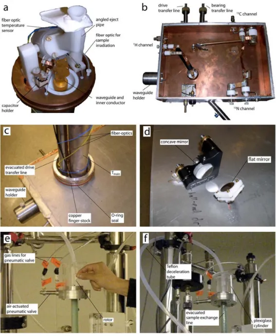
Fig. A1. Appendix. Photographs of instrument
a) Photograph of the probe. b) The inside of the probe box showing the RF circuit. c) Top of the probe-box showing the seals to the probe-dewar. d) Mirrors on the bottom plate of the probe-box for coupling microwaves from the horizontal waveguide to the vertical waveguide e) Sample insertion chamber at the top of the magnet f) Deceleration tube that gently stops the rotor during the ejection process.
NIH-PA Author Manuscript
NIH-PA Author Manuscript
NIH-PA Author Manuscript
NIH-PA Author Manuscript
NIH-PA Author Manuscript
Table 1
Isolations between three RF channels.
Power in (dB) →
Power out (dB) ↓ 13C 15N 1H
13C X -50 -20 15N -21 X -19 1H -14 -18 X