HAL Id: cea-01810034
https://hal-cea.archives-ouvertes.fr/cea-01810034
Submitted on 7 Jun 2018HAL is a multi-disciplinary open access archive for the deposit and dissemination of sci-entific research documents, whether they are pub-lished or not. The documents may come from teaching and research institutions in France or abroad, or from public or private research centers.
L’archive ouverte pluridisciplinaire HAL, est destinée au dépôt et à la diffusion de documents scientifiques de niveau recherche, publiés ou non, émanant des établissements d’enseignement et de recherche français ou étrangers, des laboratoires publics ou privés.
EAST-ADL
Hans Blom, De-Jiu Chen, Henrik Kaijser, Henrik Lönn, Yiannis
Papadopoulos, Mark-Oliver Reiser, Ramin Tavakoli Kolagari, Sara Tucci
To cite this version:
Hans Blom, De-Jiu Chen, Henrik Kaijser, Henrik Lönn, Yiannis Papadopoulos, et al.. EAST-ADL: An Architecture Description Language for Automotive Software-intensive Systems in the Light of Recent use and Research . International Journal of System Dynamics Applications, 2016, 5, pp.1 -20. �10.4018/IJSDA.2016070101�. �cea-01810034�
See discussions, stats, and author profiles for this publication at: https://www.researchgate.net/publication/303891524
EAST-ADL:: An Architecture Description Language for Automotive Software-intensive Systems in the Light of Recent use and Research
Article · July 2016 DOI: 10.4018/IJSDA.2016070101 CITATION 1 READS 122 8 authors, including:
Some of the authors of this publication are also working on these related projects: CEA LIST Blockchain ProgrammeView project
DEIS (2017 - 2020) - Dependability Engineering Innovation for cyberphysical SystemsView project Hans Blom
AB Volvo
8PUBLICATIONS 114CITATIONS
SEE PROFILE
De- Jiu Chen
KTH Royal Institute of Technology
80PUBLICATIONS 640CITATIONS SEE PROFILE Henrik Kaijser AB Volvo 7PUBLICATIONS 10CITATIONS SEE PROFILE Yiannis Papadopoulos University of Hull 140PUBLICATIONS 1,560CITATIONS SEE PROFILE
All content following this page was uploaded by Henrik Kaijser on 15 June 2016. The user has requested enhancement of the downloaded file.
EAST-ADL – An Architecture
Description Language for Automotive
Software-intensive Systems
in the Light of Recent use and
Research
Hans Blom1 , De-Jiu Chen2 , Henrik Kaijser1 , Henrik Lönn1 ,Yiannis Papadopoulos3, Mark-Oliver Reiser4, Ramin Tavakoli Kolagari5, Sara Tucci6 1
Volvo Group, Advanced Technology and Research, Gothenburg, Sweden,
<prename>.<surname>@volvo.com
2
KTH Royal Institute of Technology, School of Industrial Engineering and Management, Department of Machine Design, Mechatronics Unit, Brinellvägen 85, SE-100 44 Stockholm,
Sweden
3
Department of Computer Science, University of Hull, Cottingham Rd, HU67RX, HULL, UK,
4
NumberFour AG, Schönhauser Allee 8, 10119 Berlin, Germany,
5
Nuremberg Institute of Technology, Faculty of Computer Science, Hohfederstrasse 90489
Nuremberg, Germany, [email protected]
6
CEA, LIST, 91191 Gif sur Yvette CEDEX, France, [email protected]
ABSTRACT
EAST-ADL is an Architecture Description Language (ADL) initially defined in several European-funded research projects and aligned with AUTOSAR and ISO26262. It provides a comprehensive approach for defining automotive electronic systems through an information model that captures engineering information in a standardized form. Aspects covered include vehicle features, requirements, analysis functions, software and hardware components and communication. The representation of the system’s implementation is not defined in EAST-ADL itself but by AUTOSAR. However, traceability is supported from EAST-EAST-ADL’s lower abstraction levels to the implementation level elements in AUTOSAR. In this article we describe EAST-ADL in detail, show how it relates to AUTOSAR as well as other significant automotive standards and present recent research work on using and advancing EAST-ADL, the functional safety standard ISO 26262, heterogeneous multi / many core architectures, security and for multi-objective optimization.
Keywords: Automotive systems modelling, AUTOSAR, dependability, domain specific language, functional safety, ISO 26262, modelling tools, multi-objective optimization, software development processes, software product line engineering
INTRODUCTION
EAST-ADL is an Architecture Description Language (ADL) initially defined in the European ITEA EAST-EEA project and subsequently refined and aligned with the more recent AUTOSAR automotive standard (AUTOSAR Development Partnership, 2015) in the European FP6 and FP7 ATESST projects (ATESST2 Consortium, 2010). Currently, it is maintained by the EAST-ADL Association (EAST-ADL Association, 2015). It is an approach for describing automotive electronic systems through an information model that captures engineering information in a standardized form. The language provides a wide range of modelling entities, including vehicle features, functions, requirements, variability, software components, hardware components and communication.
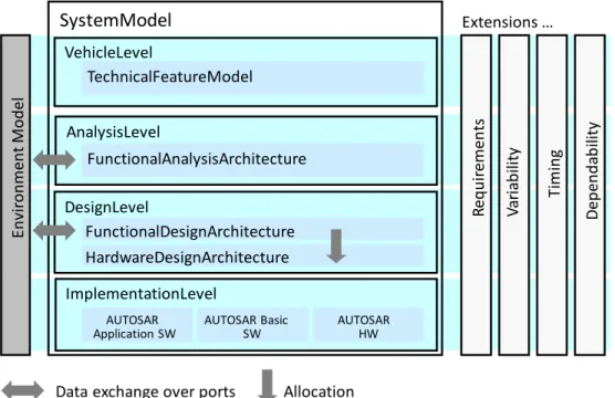
EAST-ADL clearly defines several abstraction levels (see Figure 1) and at each of these levels, the software- and electronics-based functionality of the vehicle is modelled with a different level of detail. The proposed abstraction levels and the contained modelling elements provide a separation of concerns and an implicit style for using the language elements. The embedded system is defined completely on each abstraction level, and identical parts of the model are linked across abstraction levels with various traceability relations. This makes it possible to trace an entity from feature down to components in hardware and software.
The features in the “TechnicalFeatureModel” at the Vehicle Level represent the content and properties of the vehicle from top-level perspective without exposing the realization. It is possible to manage the content of each vehicle and entire product lines in a systematic manner. A complete representation of the electronic functionality in an abstract form is modelled in the Functional Analysis Architecture (FAA). One or more entities (analysis functions) of the FAA can be combined and reused to realize features. The FAA captures the principal interfaces and behaviour of the vehicle’s subsystems. It allows validation and verification of the integrated system or its subsystems on a high level of abstraction. Critical issues for understanding or analysis can thus be considered, without the risk of them being obscured by implementation details.
SystemModel AnalysisLevel DesignLevel ImplementationLevel En vi ro n me n t M o d el FunctionalAnalysisArchitecture FunctionalDesignArchitecture AUTOSAR Application SW VehicleLevel AUTOSAR Basic SW AUTOSAR HW HardwareDesignArchitecture Va ri ab ili ty Req u ir em en ts TechnicalFeatureModel D ep en d ab ili ty Ti m in g Extensions …
Data exchange over ports Allocation
Figure 1. The EAST-ADL’s breakdown in abstraction levels (vertically) and in core, environment and extensions (horizontally).
The implementation-oriented aspects are introduced while defining the Functional Design Architecture (FDA). The features are realized here in a function architecture that takes into account efficiency, legacy and reuse, COTS availability, hardware allocation, etc. The function structure is such that one or more functions can be subsequently realized by an AUTOSAR software component (SW-C). The external interfaces of such components correspond to the interfaces of the realized functions. The representation of the implementation, the software architecture, is not defined by EAST-ADL but by AUTOSAR. However, traceability is supported from implementation-level elements (AUTOSAR) to vehicle-level elements. The Hardware Design Architecture (HDA) should be considered parallel to application development. On the Design Level and down, the HDA forms a natural constraint for development and the hardware and application software development needs to be iterated and performed together. There is also an indirect effect of hardware on the higher abstraction levels. Control strategies or the entire functionality may have to be revised to be implemented on a realistic hardware architecture. This reflection of implementation constraints needs to be managed in an iterative fashion. To verify and validate a feature across all abstraction levels, using simulation or formal techniques, an environment model is needed early on. This “plant model” captures the behaviour of the vehicle dynamics, driver, etc. The core part of the environment model can be the same for all abstraction levels.
After this short introduction to the EAST-ADL concepts, we go on to discuss the motivation and modelling concepts in more detail. The relation between EAST-ADL and its most important related approach AUTOSAR is explained throughout the following text. At the end, we will provide a more detailed discussion of other related approaches and how they compare to EAST-ADL.
Automotive embedded systems have evolved enormously over the past decades. The use of electronics and software in automotive products has grown exponentially. For example, today vehicles in series production contain the same amount of electronics as an aircraft did two decades ago. To satisfy customer demands and competitiveness between OEMs, innovation will further drive the significance of software-controlled automotive electronics over the next decade. It is obvious, that the vehicle’s electronic architecture will continue to grow in complexity, criticality and authority.
To manage some of the challenges of automotive software, the AUTOSAR consortium has developed a standardized automotive software architecture (AUTOSAR Development Partnership, 2015). One of its main features is a componentization of the software architecture, to favour reuse and assist collaboration and integration aspects. The software development effort is no longer bound to a specific hardware platform or a particular provider. A standardized software architecture and methodology is a first step towards meeting the challenges associated with the development of automotive systems, often distributed over several suppliers with different responsibilities. However, there still remains the critical issue of managing the overall engineering information to control system definition. This stage contains the most decisive steps in meeting safety challenges, controlling complexity and avoiding development errors and delays. Many stakeholders are involved here, and development is distributed over several departments and locations and involves several suppliers. While system modelling and model-based development is the trend in the automotive industry to solve this issue, there are diverse company-specific solutions. There is no standardized, comprehensive approach to support system modelling of the engineering information and therefore a federation of different modelling language initiatives is required to develop an automotive domain-specific language that is also in line with non-automotive approaches.
To support complexity and facilitate component development, an adequate organization of the system model is important. Representing the system in several “models” at different abstraction levels is a way to ensure separation of concerns and allow smooth interaction between disciplines. Supporting a functional decomposition of the system is also important to hide implementation aspects while the functional aspects are addressed. Another challenge is the capability to use product line engineering. The automotive industry is characterized by large model ranges and a high degree of customizability. In addition to end-customer configuration, also other important forms of variation occur, for example country variants arising from different legislation and variants for special purpose vehicles like ambulances or taxis. The organization and structuring of a comprehensive product line approach, from feature selection down to decomposition into components, requires innovative and efficient techniques. Finally, an important challenge is assessing the dependability of the application. In particular, means are required for early evaluation of system architecture, in terms not only of functional properties, but also of non-functional ones (such as timing, resource, safety level, etc.). In this context, the application of the standard for functional safety, ISO 26262 (International Organization for Standardization, 2011), must be prepared by introducing new techniques and a structured development approach. An architecture description language provides means to represent the safety life-cycle information according to the requirements of the standard.
Increasing processing power of embedded systems by increasing the clock frequency is about to reach its limit for single-core processors. This is due to the fact that the clock frequency in integrated circuits is linearly proportional and power dissipation calculates quadratically in the electrical power loss. As a rule of thumb, 1% reduction in the clock rate results in 3% lower energy density and 0.66% lower processing power. Since energy efficiency is viewed as a relevant feature for customers while the market requires more power at the same time, all
leading semiconductor manufacturers focus on a new generation of processors, so-called
multi- and many-core processors1. The already on-going development from single core to
multi core processors is continued by the use of heterogeneous cores because cores focussed on specific tasks cores yield even better energy efficiency. The advantage of multi core processors compared to single core processors is higher processing power while providing better dissipation efficiency. However, the transition to multi-core technology does not only come advantageous: In a study of VDC Research (VDC research, September 2010) developers, architects, and project managers were interviewed about their estimation of expenses while migrating to multi core architectures. The experts anticipated development costs to be four times as high as in the single core case, a prolongation of projects by 25%, and involving three times as many engineers in the projects. Although this certainly only applies to the transfer phase one may expect additional expenses generally due to the new technical challenges (for developers, architects, and project managers). In single core systems, a sequential execution model is used, which offers the advantage of a fully deterministic execution of the program code. Multi core systems offer true parallelism in the execution and processing, providing the advantages mentioned above. So, for example, functionality and data must be allocated to cores, taking dependencies and constraints with respect to individual cores into account. The developers of these systems are faced with a significant increase in complexity of the new systems. The challenge of supporting the transition of the traditional single core automotive system development to a heterogeneous multi and many core development is taken up by the recently started research project FORMUS³IC (Multi-Core Safe and Software-intensive Systems Improvement Community, September 2015) funded by the Bavarian Research Foundation. The focus of the overall project on heterogeneous multi / many core architectures for automotive (and avionics) is also reflected in the modelling language: EAST-ADL and AUTOSAR as the established standards in the automotive domain are taken as a basis for the documentation and the time simulation of heterogeneous multi / many core architectures. Within FORMUS³IC the modelling languages are used for the internal communication and specification of the systems of interest; at the same time it shall be analysed if the modelling languages are appropriately equipped with modelling entities making the modelling of heterogeneous multi / many core architectures possible. AUTOSAR, for example, states that it is able to represent multi core qualities. Based on challenging heterogeneous multi / many core scenarios, FORMUS³IC will analyse these abilities. EAST-ADL is equipped with modelling entities making it possible to extend the language according to specific user needs (“User Attributes”). The previously mentioned scenarios are just as well applicable to the EAST-ADL and shall unleash the necessity to extend EAST-ADL with specific modelling entities for the purpose of modelling heterogeneous multi / many core architectures. The findings shall even be compared to similar initiatives of the avionics domain such that these concepts can be applied across different domains (automotive and avionics). The EAST-ADL methodology may need to be adapted as well in order to reflect software engineering steps for simulation and analysis of the behaviour of a heterogeneous architecture on the hardware level, e.g., information about non-functional properties, such as run duration and energy consumption necessary for an early simulation on the engineering levels of abstraction (i.e., Analysis Level and Design Level) is obtained from the simulation of the real hardware by specific tools and mock-ups. These specific tools normally take much more system knowledge into account than necessary on the engineering levels. In order to closely relate the engineering levels with the hardware level information, the modelled non-functional attributes need to be cross-referenced to the final code that is taken as a basis for
1
According to the mentioned rule of thumb one can calculate that a dual core processor has an increased processing power of 180%, while supply voltage is decreased by 15% compared to single core processor of the same performance budget.
the simulation of the complete hardware system, i.e., kept as some kind of a notation in a precompile step within the assemble program.
Safety and dependability according to the ISO 26262 standard is well supported in the EAST-ADL. Innovative automotive features like car-to-X communication via WLAN, autonomous driving, and the increasing amount of data collection for vehicle diagnostics require advanced security measures starting even from the very early system development phases, captured in the more abstract levels of the EAST-ADL. Future development processes for automotive systems need to take security seriously and need to investigate safety and security at the same and together with each other. The research project FORMUS³IC plans to look into this aspect with special reference to the avionics domain, where advanced security measures are state of the art. But the necessary broad investigation of a comprehensive dealing of automotive safety and security for the car as a cyber-physical system is an open research question with possibly enormous consequences for the development processes and possibly even for the respective modelling language, i.e., AUTOSAR and EAST-ADL.
Finally, tool support for engineering development is organized today as a patchwork of heterogeneous tools and formalisms. A backbone environment using a standardized modelling language has to be harmonized to drive the tool market. Modelling EAST-ADL is most comfortable with MetaEdit+ from MetaCase but there exists no seamless integration from the EAST-ADL model of MetaEdit+ (or any other EAST-ADL modelling tool) to tools that naturally would follow up, e.g., tools for modelling the system in AUTOSAR (with tools from, e.g., Vector, Elektrobit, dSpace, ETAS, Arccore). But a standard xml format has been defined for tool interoperability between EAST-ADL modelling tools. The EAST-ADL model, especially the Design Level, could easily be taken as a starting point for later AUTOSAR modelling on the system level.
EAST-ADL META-MODELLING APPROACH
The EAST-ADL language is formally specified as a meta-model capturing domain specific, i.e., automotive concepts. The meta-model follows guidelines originating from AUTOSAR (AUTOSAR Development Partnership, 2015) for definition of templates. Modelling concepts are represented by the basic notions of MOF (Object Management Group, 2015, June) supplemented by the AUTOSAR template profile. The meta-model thus fits as a specification of a domain-specific tool environment, and also defines an XML exchange format (called EAXML, similar to the AUTOSAR exchange format ARXML). This domain model represents the actual definition of the EAST-ADL language and constitutes the heart of the EAST-ADL language specification.
In addition to the domain model, the EAST-ADL language is also implemented as a UML2 profile. UML profiles are standard extension mechanisms in the UML2 language, in which domain-specific concepts are provided as tags applicable to a selected subset of UML2 elements (such as classes, properties, ports, etc.) giving them different meaning and extra properties. The profile allows users to do system modelling according to the EAST-ADL semantics using off-the-shelf UML2 tools. Constraints are also part of the profile definition; this makes it possible to constrain the rich set of modelling constructs allowed by UML2 and to validate the conformance of the model. The EAST-ADL profile is delivered as an XMI file ready for use in UML2 tools. In the definition of the EAST-ADL profile, the general strategy has been to provide stereotype properties even for properties already populated within the UML2 superstructure. In other words, the property values that appear when defining a UML2 model are duplicated with semantic names in the stereotypes. This yields a model that is quite complete even without a profile. This approach is in line with the intention of UML2 that views and features of existing UML2 tools can be used readily, including for example, UML2
activity diagrams and related profiles such as SysML (Object Management Group, 2015) and MARTE (Object Management Group, 2011, June). The applied profile adds automotive semantics to this self-contained UML2 model.
EAST-ADL MODELLING CONCEPTS
The modelling concepts of EAST-ADL fall into six areas: functional abstraction, timing modelling, requirements modelling, functional safety modelling, variability modelling, behaviour constraint modelling, and visualization.
Functional Abstraction
EAST-ADL provides the means to capture the functional decomposition and behaviour of the embedded system and the environment.
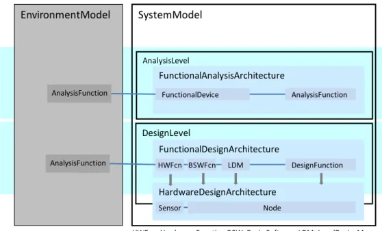
SystemModel AnalysisLevel DesignLevel EnvironmentModel FunctionalAnalysisArchitecture FunctionalDesignArchitecture HardwareDesignArchitecture FunctionalDevice AnalysisFunction HWFcn BSWFcn LDM DesignFunction Sensor Node AnalysisFunction AnalysisFunction
HWFcn=Hardware Function BSW=Basic Software LDM=LocalDeviceManager Figure 2. Functional decomposition in EAST-ADL on Analysis Level and Design Level.
At the Analysis Level, the “FunctionalAnalysisArchitecture” contains “Functions” that can be hierarchically composed and connected to one another. Functional devices represent sensors and actuators with their interface software and electronics, and these are connected to the environment. Figure 2 explains the entities involved and shows how they are connected. The “Functions” can have two types of ports, “FlowPorts” and “ClientServer” ports to represent data exchange and client-server interaction. The functions can be hierarchical, but the leaves have synchronous execution semantics, which means that they read inputs, calculate and provide outputs. They are triggered based on time or data arrival on ports. A function’s internal behaviour is typically defined by external tools and their techniques for behavioural descriptions. The behaviour of the environment is captured in the “EnvironmentModel”. The environment model also contains “Functions”, but they represent vehicle dynamics, other vehicles, road-side IT systems, etc.
The Design Level (see Figure 2) contains a more detailed functional definition of the system. “Functions” and “LocalDeviceManagers” represent application software in the Functional Design Architecture. “BasicSoftwareFunctions” are used to capture middleware behaviour
affecting application functionality. “HardwareFunctions” represents the logical behaviour of hardware components and complete the logical path to the environment model with the controlled “plant” and surrounding elements. The Hardware Design Architecture represents the resource platform with ECUs, busses, sensors, actuators and I/O to which the functions are allocated. The Hardware Design Architecture also reflects the physical topology of electrical elements and connectors.
Timing Modelling
EAST-ADL provides support for model-specific engineering information, including non-functional properties that are relevant for the timing of automotive functions. Conceptually, timing information can be divided into timing requirements and timing properties, where the actual timing properties of a solution must satisfy the specified timing requirements.
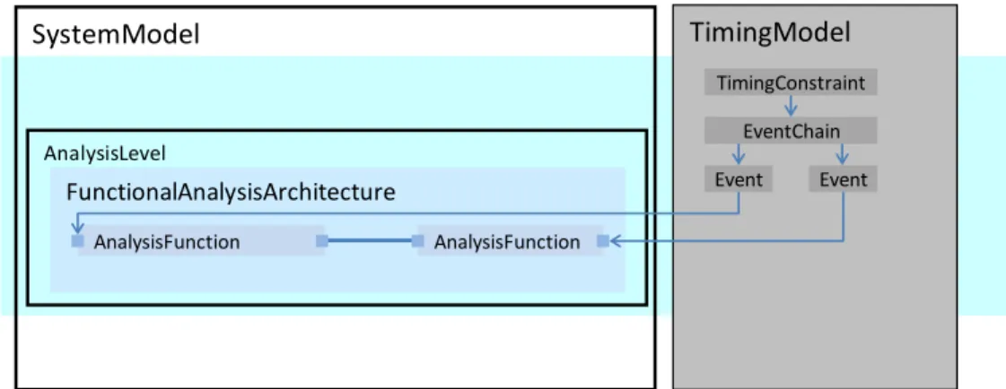
Modelling of timing requirements and properties on the functional abstraction levels of the architecture description language is done by means of the „Timing Augmented Description Language“ (TADL) developed by the TIMMO project (TIMMO Consortium, 2012). In the Implementation Level, i.e. AUTOSAR, this is addressed by the „AUTOSAR Timing Extensions“ which was introduced in AUTOSAR release 4.0 (AUTOSAR Development Partnership, 2015). Timing constraints are defined separately from the structural modelling and reference the structural elements of the EAST-ADL. The requirements modelling support in EAST-ADL allows for tracing from solutions as modelled in the structural model to requirements, and from verification cases to requirements. Form the perspective of the requirements support, TADL constraints can be perceived as refinements of the requirements. The fundamental concept for describing timing constraints is that of Events and Event Chains. On every level of abstraction, observable events can be identified, e.g. events that cause a reaction, i.e. a stimulus, and resulting observable event, i.e. a response. Timing requirements can be imposed on Event Chains, for example, specifying that the time between the occurrence of a stimulus event and the occurrence of the expected response event shall not exceed a specific amount of time, e.g. an end-to-end delay from a sensor to an actuator. In addition, requirements regarding the synchrony of events can be expressed, stating that a number of events shall occur „simultaneously“ in order to cause a reaction, or be considered as valid response of a system function. For example, in case of a passenger vehicle, its brake system shall apply the brakes simultaneously; or the exterior light system shall simultaneously turn on and off the rear and front turn signal indicators.
TimingModel SystemModel AnalysisLevel FunctionalAnalysisArchitecture AnalysisFunction AnalysisFunction Event Event EventChain TimingConstraint
Figure 3 shows a simple example of an event chain with an annotated reaction constraint. A Functional Analysis Architecture with two functions builds up the structural model. The constraint with bound attributes has been defined. This refers to an Event Chain built up by an in event (stimulus) and an out event (response) referring to structural ports.
Requirements Modelling
In order to comprehensively support the development of complex automotive systems, EAST-ADL provides means for requirements specification, i.e., for specifying the required properties of the system (at varying degrees of abstraction). Furthermore, requirements can be refined by behavioural models, they can be traced between system refinement and system decomposition levels, and they can be related to verification and validation information and activities. Another important aim of EAST-ADL is to provide means for project-specific adjustments to requirements specification structures, which are inspired by the Requirements Interchange Format (Object Management Group, ReqIF, 2013).
Methodically, EAST-ADL differentiates between functional requirements, which typically focus on some part of the “normal” functionality that the system has to provide (e.g. “ABS shall control brake force via wheel slip control”), and quality requirements, which typically focus on some external property of the system seen as a whole (e.g. performance, “ABS shall reduce stopping distance on snow by 40%”). EAST-ADL offers detailed means to model artefacts of verification and validation activities and to relate these artefacts to requirements. This allows us to explicitly and continuously plan, track, update and manage important V&V activities and their impact on the system parallel to the system’s development.
Functional Safety Modelling
The overall objective of the support for functional safety modelling is to enforce explicit considerations of safety concerns throughout an architecture design process, which includes all safety related information that are necessary for developing a safety critical E/E system, in compliance with the Standard ISO 26262, an international standard dedicated to functional safety for road vehicles (International Organization for Standardization, 2011).
As an overall system property, safety is concerned with anomalies (e.g. faults, errors and failures) and their consequences under certain environmental conditions. It is one particular aspect of system dependability that normally also encompasses reliability, availability, integrity, maintainability and security. Functional safety represents the part of system safety that depends on the correctness of a system in performing its intended functionality. In other words, it addresses the hazardous events of a system during its operation (e.g. component errors and their propagations).
EAST-ADL facilitates safety engineering in terms of safety analysis, specification of safety requirements, and safety design. While promoting safety in general through its intrinsic architecture modelling and traceability support, EAST-ADL provides explicit support for efficient integration of functional safety activities along with the nominal architecture design and evolution. As illustrated in Figure 4, EAST-ADL provides modelling means for the concepts defined in ISO 26262, including vehicle-level hazard analysis and risk assessment, the definition of safety goals and safety requirements, the ASIL (Automotive Safety Integrity Level) decomposition and the error propagation. The information is included in the Dependability package, as an extension of the nominal architecture model.
Figure 4. Mapping of ISO26262 information to EAST-ADL abstraction levels.
Following a top-down approach, the safety analysis starts at the Vehicle Level, beginning with the identification and description of the item. An item, as defined in ISO 26262, is a system or array of systems or functions that is of particular concern in regards to functional safety. Through hazard analysis and risk assessment activities, is possible to preliminarily evaluate at Vehicle Level the “safety relevance” of the item under safety analysis, to define the safety goal (top-level safety requirement) for each hazardous event (hazard evaluated in different scenarios) and to classify them in terms of ASIL. Moreover, Analysis Level and Design Level of EAST-ADL support respectively the functional safety concept and the technical safety concept definition.
Dependability ErrorModel FunctionalAnalysisArchitecture SystemModel AnalysisLevel AF1 AF3 EM1 EM2 AF2 FaultFailure SafetyConstraint ASIL=C
Figure 5. EAST-ADL error model as a separate architecture view extending the nominal architecture model.
EAST-ADL error modelling allows capturing detailed information about the failure behaviour of the system and thus enables a safety analysis to determine whether technical safety requirements are being met. This Error Model describes the generation and propagation of failures through the system. The relationships of local error behaviours are captured by means
of explicit error propagation ports and connections. Within an error model, the syntax and/or semantics of existing external formalisms can be adopted for a precise description of the error logic. The specification captures what output failures of the target architecture component are caused by what faults of this component. This, together with the error propagation links, makes it possible to perform safety simulations and analyses through external analysis tools. In an architecture specification, an error is allowed to propagate via design specific architectural relationships when such relationships also imply behavioural or operational dependencies (e.g. between software and hardware).
The error modelling is treated as a separate analytical view (see Figure 5). It is not embedded in a nominal architecture model but seamlessly integrated with the architecture model through the EAST-ADL meta-model. This separation of concerns in modelling is considered necessary in order to avoid some undesired effects of error modelling, e.g. relating to the comprehension and management of nominal design, reuse, and system synthesis (e.g. code generation).
Given an error model, the analysis of the causes and consequences of failure behaviours can be automated through tools. There is currently a (prototype) analysis plug-in in the Eclipse environment allowing the integration of the HiP-HOPS tool (Hierarchically Performed Hazard Origin and Propagation Studies1) for static safety analysis in terms of FFA, FTA, and FMEA (Papadopoulos et al., 2011). The analysis leverage includes fault trees from functional failures to software and hardware failures, minimal cut sets, FMEA tables for component errors and their effects on the behaviours and reliability of entire system.
In EAST-ADL, a safety requirement derived from the safety analysis has attributes specifying the hazard to be mitigated, the Automotive Safety Integrity Level (ASIL), operation state, fault time span, emergency operation times, safety state, etc. The safety requirement is then traced to other nominal requirements or used to derive other nominal requirements from it, e.g. relating to safety functions and performance.
This sophisticated management of information across layers of the architecture can help to deal with complexity and ensure the traceability of the safety requirements. However, while this approach is a step forward towards managing the design lifecycle, there remain significant practical obstacles when decomposing high-level safety requirements over layers of refined architectures. Such problems may include ensuring that independence constraints are met, by working efficiently through the many possible combinations for allocations, and ensuring that the decomposed low-level requirements still add up to the original high-level requirements. All of these add to the time, expense, and complexity of following safety standards like ISO 26262 when dealing with the types of detailed electronic architectures that are common in modern safety-critical systems, often to the extent that performing the process manually is practically impossible.
Representation and linking of information is a necessary but not sufficient condition for addressing the above issues. Experimental efforts have shown that the EAST-ADL information can be used to automated the process of allocation of safety requirements, in conjunction with the HOPS safety analysis tool. Using the EAST-ADL model, HiP-HOPS can synthesise fault trees for a system, indicating how the individual component failures can propagate throughout the rest of the system and lead to hazard conditions in the system output functionality. On the basis of this information, it is possible to automatically decompose high-level SILs to subsystems and components of a progressively refined architecture. HiP-HOPS is aware of which components are independent by means of the propagation model and the fault tree analysis, and it can automatically apply the type of SIL 'algebra' described by e.g. ISO 26262 and ARP4754-A. The result is an allocation of SILs to individual components, component ports, or even component failure modes, in such a way
that the overall high-level requirements are still fulfilled (Papadopoulos et al., 2010) Work has focused on the use of metaheuristic optimisation algorithms to more efficiently explore the large spaces of potential allocation solution that may yield different costs [5]. Work on this has included genetic algorithms (Parker et al., 2013) and Tabu search (Azevedo et al 2014). All of these have produced very promising results that are far more efficient and scalable than deterministic solutions, and a prototype implementation has been incorporated into HiP-HOPs and integrated with the EAST-ADL analysis framework as part of the recent EU FP7 project MAENAD (MAENAD Consortium, 2012).
Variability Modelling
EAST-ADL variability management starts on the Vehicle Level, where model range features and variability are represented. At this point, the purpose of variability management is to provide a highly abstract overview of the variability in the system such as the complete system together with dependencies between these variabilities. A “variability” in this sense is a certain aspect of the complete system that changes from one variant of the complete system to another. “Abstract” here means that, for an individual variability, the idea is not to specify how the system varies with respect to this variability but only that the system shows such variability. For example, the front wiper may or may not have an automatic start. At Vehicle Level, the impact of this variability on the design is not defined; only the fact that such
variability exists is defined by introducing an optional feature named
„RainControlledWiping“. This is subsequently validated and refined during analysis and design.
One or more feature models may be defined on the Vehicle Level: the so-called core Technical Feature Model is used to define the complete system’s variability on a global level from a technical perspective, whereas one or more optional Product Feature Models can be used to define views on this technical variability which can be tailored to a particular view-point or purpose, e.g. the end-customer perspective.
While the details of how variability is actually realized in the system are largely suppressed at the Vehicle Level, they are the focus of attention when managing variability in other areas of the development process. In fact, specific variability may lead to modifications in any development artefact, such as requirements specifications and functional models. Here, describing that a specific variability occurs is not sufficient; it is necessary to describe how each variation affects and modifies the corresponding artefact.
The purpose of feature modelling is to define the commonalities and variabilities of the product variants within the scope of a product line. Feature models are normally used on a high level of abstraction, as described above for Vehicle Level variability. However, in EAST-ADL, they are also used on Analysis Level and Design Level and acquire a much more concrete meaning there. Configuration decision modelling, on the other hand, is aimed at defining configuration: the configuration of a feature model fT – i.e. the selection and deselection of its features – is defined in terms of the configuration of another feature model
fS. A configuration decision model can thus be seen as a link from fS to fT that allows us to
derive a configuration of fT from any given configuration of fS. In EAST-ADL, this
mechanism is used to define how a certain configuration on a higher abstraction level affects the binding of variability in lower-level components.
Variability management on the artefact level is driven by the variability captured on the Vehicle Level. This means that the main driver for variability and also variability instantiation is the vehicle-level feature model. Variability on the artefact level essentially consists of the definition of variation points within these artefacts. In addition, feature models can be
attached to functions in order to expose the variability within these functions and hide the actual structuring, representation and binding of this variability within a function. This way, the benefits of information hiding can now be applied to the variability representation and variability binding within the containment hierarchy of functions in the EAST-ADL Functional Analysis Architecture and Functional Design Architecture (called compositional variability management).
The variability mechanisms of EAST-ADL are central to recent research efforts towards using the language for supporting advanced exploration of design spaces and automatic optimisation of models (Walker et al., 2013). Design is not an exercise where the final outcome is the only possible one. There are typically possibilities for including and excluding features in a product. There are also options for using different off-the-shelf components that have different costs, reliability and performance. Furthermore, there are architectural choices which are often fairly standardised, either conforming to known design patterns, or representing different known solutions to delivering specific functionalities. The various ways in which options can be employed in a product define a potential design space which contains many variants of the product, with each variant giving different outcomes in terms of function, dependability and cost. In realistic scenarios of design, this potential design space can expand very rapidly. For instance, in a system of n components, if there are two versions
for each component then there are 2n system variants, which equates to 1.12e15 variants when
n=50. All these configurations entail different costs and give different performance in terms of system dependability which raises the question which configuration is optimal, e.g. meets dependability requirements with minimal costs.
In EAST-ADL, it is possible to express variability in a model and later on resolve variability to get specific instances of a product. These instances can be evaluated for various attributes, so that those instances that perform better according to certain criteria can be selected for implementation. In the MAENAD project (MAENAD Consortium, 2012), we have shown that the process of variability resolution, evaluation and optimal selection can be automated with the aid of metaheuristics such as Genetic Algorithms. Variability mechanisms can be used to define multiple alternative implementations for components. For example, a sensor can be chosen from two different suppliers, with each choice having its own cost, weight, performance, and failure characteristics. Subsystems can also carry alternatives, e.g. a subsystem can have two different implementations that provide the functions using different sets of components and different architectures. There can be options for replication of components with known patterns of fault tolerance, e.g. a primary-standby configuration, or multiple parallel channels with majority voting. There can also be options for allocation of functions to different electronic control units.
Once the EAST-ADL system model has been annotated to include these options, the model can be subjected to an evolutionary optimisation process. In the context of this process, populations of candidate designs are created by resolving the variability of the model, i.e., fixing variation points by selecting particular design options. Each candidate design is then evaluated with respect to the objectives of the optimisation. Best designs are selected, new populations are created using genetic operators and the process is iterated with progressively noticeable improvement in the outcomes. Experiments with optimisation of models with respect to dependability, schedulability and cost are described in (Walker et al., 2013).
Behaviour Constraint Modelling
The reasoning and analysis of dependability & performance involve many aspects in a system’s lifecycle. To this end, EAST-ADL allows precise and integrated annotations of various behavioural concerns related to requirements, application modes and functions,
implementation and resource deployment, and anomalies. The approach is architecture‐ centric as all behaviour annotations are formally connected to a set of standardized system artefacts and lifecycle phases. This is fundamental for many overall design decisions, such as requirements engineering, component compositionality & composability, design refinements, safety engineering, maintenance, etc. From a wider perspective, this language support enables an integration of many existing modelling and analysis technologies, such as from computer science and electronic engineering, by making it possible to trace and maintain the related engineering concerns and analytical information coherently using EAST-ADL.
Based on a hybrid-system semantics, the EAST-ADL support for the annotations of behavioural concerns consists of three categories of behaviour constraints:
1. Attribute Quantification Constraint – relating to the declarations of value attributes
and the related a-causal quantifications (e.g., U=I*R).
2. Temporal Constraint – relating to the declarations of behaviour constraints where
the history of behaviours on a timeline is taken into consideration.
3. Computation Constraint – relating to the declarations of cause-effect dependencies
of data in terms of logical transformations (for data assignments) and logical paths. Each of these behaviour constraints can be associated to time conditions given in terms of logical time, of which the exact semantics is given by the existing EAST-ADL support for timing definition (e.g. the triggering, and port data sending & receiving events of a function). Owing to the formal semantics, one can explicitly define the model transformation from EAST-ADL behaviour model to other model formats of external analysis methods and tools, such as hazard analysis, response time analysis, model checking, test-case generation, etc.
VISUALIZATION
Visualization is fundamental to provide efficient operations and promote understanding when working with EAST-ADL models in tools. There are two common visualization techniques in the current tool landscape for EAST-ADL: tree view and diagram. A tree view shows the real and virtual containment hierarchy of the model, where the metaclass of each model element is typically identified by an icon and/or appended to the name. The tree view is space efficient and suitable for arbitrarily sized models. Virtual elements arise due to the typeprototype
pattern: Consider a type T that contains an element E, then each prototype instance PT of T
has a virtual containment of E, i.e. there is a virtual E element owned by PT. Figure 6 shows
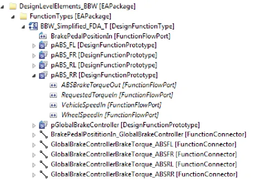
an example of a simplified Brake-By-Wire (BBW) model in the EATOP application (EATOP 2015). The model has an ABS controller for each wheel and a global brake controller that distributes the torque requested by the driver on the wheels before ABS is taken into account. A more complete model would also contain sensor elements to obtain the speed of each wheel, as well as actuators for applying the desired brake torque on each wheel. Real model elements have their name displayed in normal text, while virtual model elements are displayed in italics.
Figure 6. Tree view of a simplified BBW model on the design level.
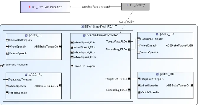
A diagram view shows the model elements and their relations on a canvas. The explicit visualization of relations is an advantage compared to the tree view. On the other hand, the diagram view is only appropriate for small models or limited extracts of large models. If there are too many elements in the same diagram it becomes obscure and a tree view works better. The EAST-ADL model file does not contain diagram information. Instead, information pertaining to a diagram, i.e. geometry, colour and other visual attributes, is stored in a separate graphical model file, together with the package paths to the represented model elements. This provides separation of concerns and a convenient way to have an arbitrary number of diagrams for the same ADL elements. Different aspects of the same EAST-ADL model will be relevant to visualize for different stakeholders. Figure 7 shows the same simplified BBW model in a diagram created with the GEFEditor plugin of the EATOP application (Baci et al., 2015). The diagram also contains a requirement R1_Torque-Distribution on the static distribution of the driver requested brake force. The requirement is satisfied by the pGlobalBrakeController component.
Figure 7. Diagram of the simplified BBW model in figure 6, with an additional requirement.
The GEFEditor relies on the package path references to keep the diagram and EAST-ADL models synchronised. Model element listeners are used on both models to detect any changes in one of the models that need to be reflected in the other.
METHODOLOGY
The purpose of the EAST-ADL methodology is to give guidance on the use of the language for the construction, validation and reuse of models for automotive embedded software. The purpose is thus not to impose a specific development process, but to show one sequence of steps that can produce sound and useful EAST-ADL models. This provides understanding for the EAST-ADL language and serves as building blocks for a more complex and complete process definition.
The EAST-ADL methodology is defined as a core part which is complemented by extensions. The core is a top-down description of the most central steps in each phase:
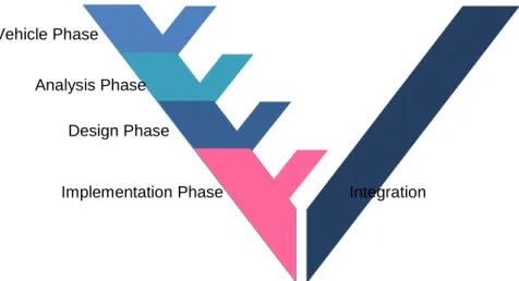
The Vehicle phase involves analysis of external requirements based on which a
Technical Feature Model is constructed. This Feature tree shall be organized in an adequate way and also capture necessary or intended feature configurations. In addition, for each feature a set of requirements is specified.
The Analysis phase results in a FunctionalAnalysisArchitecture, which specifies a
realization of the Features. The solution is a logical representation of the system to be developed. All the modelling in this phase will be on a logical behaviour level, i.e. it will make no distinction between HW and SW or about the implementation of communication.
The Design phase involves defining the FunctionalDesignArchitecture specifying a
solution to the requirements in terms of efficient and reusable architectures, i.e. sets of (structured) HW/ SW components and their interfaces, a hardware architecture, and a mapping from functional components to HW/SW components. The architecture must satisfy more detailed constraints.
The Implementation phase results in the HW/SW implementation and configuration of the final solution. This part is mainly a reference to the concepts of AUTOSAR, which provides standardized specifications at this level of automotive software development.
Figure 8. The typical basic structure of automotive system development according to the V-model.
The core methodology is extended into a comprehensive methodology for automotive development projects by adding additional and orthogonal activities to each of these phases:
Specification of Requirements and corresponding V&V cases to be executed and
evaluated during the corresponding integration phase. V&V cases are most typically test cases, but can also include reviews etc.
Verification of the model on a given abstraction level to the requirements of the model
at the abstraction level directly above.
V&V activities on the model artefacts of a given level itself, i.e. peer reviews, consistency checks, check of modelling guidelines etc.
While the methodology tries to be comprehensive handling the construction phases, the integration activities are only covered inasmuch they involve V&V activities and the relation to V&V-artefacts defined in the construction phases.
The EAST-ADL methodology is extended beyond the core activities by means of a set of methodology extensions. In the first approach for EAST-ADL methodology, different methodology versions were defined depending on scope. Examples of scope were:
Environment Modelling: modelling of the (typically analogue or discrete-analogue)
environment of the system to be developed.
Safety Assurance: development of Safety-critical systems.
Timing: detailed handling of timing requirements and properties.
Variability Modelling: detailed handling of variability modelling.
Behaviour modelling: detailed handling of behavioural modelling.
The initial EAST-ADL methodology definition is using concepts of the Software & Systems Process Engineering Meta-model SPEM (Object Management Group, 2008), which means that the methodology is based on a set of elementary work tasks, which are performed by a set of actors and produce a set of output artefacts from a set of input artefacts. These tasks are structured into disciplines and then presented to the end user by a set of views. This leads of a highly linked network of methodological activities in which an end user can easily navigate to get information and guidance on the use of the language for particular development tasks.
Vehicle Phase
Analysis Phase Design Phase
The methodology definition is currently being restructured to follow a Generic Methodology Pattern, where the EAST-ADL phases are divided into a set of steps. The set of steps are the same for each phase, and also for each aspect (safety, timing, variability, etc.). The principle is that the user assesses the steps related to the core and each relevant aspect and then implicitly “weaves” an appropriate set of steps for his needs. The notation for this more recent methodology is Business Process Modelling Notation.
BEHAVIOUR ANALYSIS
As mentioned in the Behaviour and Constraint Modelling section, the formal semantics of EAST-ADL models makes it possible to transform them to other model formats in order to perform analysis in suitable tools. This is possible since EAST-ADL provides dedicated behaviour elements that facilitate the description of the relationship between behavioural and structural models. The EAST-ADL functions have synchronous execution semantics, and language concepts are available to define their triggering and timing. By clearly distinguishing between component execution and component logical computation, EAST-ADL allows the integration of behaviour models from off-the-shelf tools like SCADE, ASCET, Simulink, etc., according to lifecycle stages and stakeholder needs. For continuous-time behaviour, i.e. for the vehicle dynamics under control, related modelling techniques from Modelica, which combines non-causal modelling with object-oriented thinking, have been adopted. The Functional Mockup interface (FMI standard, 2015), used for co-simulation and model exchange via black-box Functional Mockup Units (FMUs) has been investigated, and a prototype transformation tool to import FMUs to EAST-ADL has been developed. There is also a tool prototype for transforming EAST-ADL models to the SPIN (Simple PROMELA Interpreter) model checker.
Recent work (Marinescu et al., 2014) provides an illustrating example of behaviour analysis by simulation and model checking. Tool prototypes were developed for transforming an EAST-ADL model on the design level to a Simulink model or a timed automata (TA) model. In the used approach, the generated global behaviour model is analysed by simulation in Simulink or model-checking in UPPAAL. In both cases, the global behaviour model is generated by integrating the behaviour models associated with the functional leaf elements according to the structure of the EAST-ADL model. The two cases were verified by applying them on a Brake-By-Wire (BBW) model.
In the Simulink case, behaviour is represented in the EAST-ADL model as either FMUs or Simulink models. The specified timing and triggering behaviours are transformed by applying specific Simulink patterns in the global behaviour model. Each requirement is represented formally in the EAST-ADL model as a Generic Constraint that requires an associated Boolean monitor function to be true. The monitor function represents the requirement logic and is included in the global behaviour model to verify the requirements during simulation in Simulink.
In the UPPAAL case, behaviour is represented in the EAST-ADL model as Simulink models. The transformation to the network of TA produces two TA for each EAST-ADL leaf function. One Interface TA is automatically generated that captures the formal semantics of the EAST-ADL model in terms of timed transition systems. One Behaviour TA is manually created to capture the desired behaviour of the corresponding Simulink model associated with the function. Requirements are formalized as TCTL properties and model checking in UPPAAL is applied to verify that they hold on the model.
Both model transformations preserve the structure of the source EAST-ADL model, which is important since it simplifies the understanding and debugging of the global behaviour model.
Analysis in Simulink was successfully used to verify the requirements on the BBW model. For the exhaustive model checking approach, state explosion implied that the EAST-ADL model had to be downscaled to be useful. Statistical model checking was then applied to accomplish requirement verification on the full BBW model.
RELATED APPROACHES
One key aspect of the development of EAST-ADL is to benefit from existing methods and techniques and also to influence emerging approaches. Whenever possible, existing and state-of-the-art solutions were reused and integrated in the language. This favours the wide use of the language, allows the use of available tools and prepares for a sound standardization process. Efforts like AUTOSAR (AUTOSAR Development Partnership, 2015), TIMMO (TIMMO Consortium, 2012), and ISO 26262 (International Organization for Standardization, 2011) are sources both for the alignment of domain specific challenges and for the integration of technologies and methodologies in the development of EAST-ADL.
As a future de-facto standard for automotive embedded systems, AUTOSAR addresses the needs for a process-safe integration of functions. It provides a standardized platform for the specification and execution of application software, an integration method for software components and hardware resources, and also the interchange formats that these require. While adopting AUTOSAR for the Implementation Level, the EAST-ADL language complements the AUTOSAR initiative by providing higher-level abstractions, analysis and lifecycle management support. In effect, it allows an AUTOSAR-compliant software architecture being extended with models relating to the design of functionality, timing and safety, the structuring and allocation of application, as well as the management of variability, requirements, traceability and verification and validation.
EAST-ADL integrates the results of TIMMO, which is an ITEA project focusing on the timing constraints and timing properties in automotive real-time systems. TIMMO has developed a formal description language, TADL, and a methodology for dealing with the timing concerns on the basis of EAST-ADL 1. It has been developed in a close collaboration with AUTOSAR. The follow-up project TIMMO-2-USE further developed the TADL language, in close collaboration with the MAENAD project (MAENAD Consortium, 2012), developing EAST-ADL.
The emerging international standard ISO 26262 (International Organization for Standardization, 2011) is carefully considered in EAST-ADL. The key content includes an automotive safety lifecycle, an automotive specific approach for determining risk classes and deriving safety requirements based on ASILs (Automotive Safety Integrity Levels), and a set of requirements for validation and confirmation measures to ensure a sufficient and acceptable level of safety being achieved.
A further standardization effort being taken into consideration is the SAE “Architecture and Analysis Description Language (AADL)” (Feiler et al., 2006), which has its roots in the avionics domain. Compared to EAST-ADL, AADL has a more narrow scope: no explicit support is provided for variability management or requirements refinements and traceability. Specifics for automotive systems such as the networks are weakly supported. The AADL is not designed for mass-produced systems and therefore has less emphasis on optimized overall solutions e.g. by considering compact runtime systems. For the automotive domain, the clash with AUTOSAR concepts is also a problem. However, wherever applicable, AADL concepts were reused, e.g. for dependability modelling.
EAST-ADL allows the adoptions of existing formalisms for the underlying semantics and provides support for model transformation and tool interoperability with the external safety
analysis techniques. In particular, HiP-HOPS and the AADL’s Error Model Annex have been carefully considered in the development of EAST-ADL. They both enable the modelling of system failure behaviour and allow analysis of that behaviour using tools.
A tool plug-in for HiP-HOPS has been developed to support both FTA and FMEA. Other approaches to model-based safety analysis and verification that have been investigated for the development of EAST-ADL include ISSAC and its predecessor ESACS in the aerospace industries (where the goal was to develop a formal methodology and tools for the safety analysis of complex aeronautical systems), the ASSERT project (with similar goals but more focused on software intensive systems specified in AADL), the SETTA project (focusing on the use of time-triggered architectures in automotive systems), and the SAFEDOR project (which aimed to develop new practices for the safety assessment of maritime systems).
SPEEDS (Speculative and Exploratory Design in Systems Engineering) is a European project aiming at providing support for modelling and analysis of complex embedded systems through the usage of formal analysis tools. EAST-ADL complements the SPEEDS approach with automotive architecture and lifecycle information. The techniques of SPEEDS have been considered in EAST-ADL for behaviour modelling (i.e., with the hybrid automata variant) and for a more formal specification of requirements and constraints (i.e., with temporal logics scripts for contracts of functionality, safety, and timing).
MARTE (Object Management Group, 2011, June) is a UML profile for Modelling and Analysis of Real-Time and Embedded systems. MARTE models real-time constraints and other embedded systems characteristics, such as memory capacity and power consumption. MARTE supports modelling and analysis of component-based architectures, as well as a variety of different computational paradigms (asynchronous, synchronous, and timed). The EAST-ADL UML-profile is released as an annex to MARTE, done in the ATESST2 and ADAMS projects.
The OMG Systems Modelling Language (Object Management Group, 2015) is a general-purpose graphical modelling language for specifying, analysing, designing, and verifying complex systems that may include hardware, software, information, personnel, procedures, and facilities. Compared with ADL, SysML is more generic and high-level, so EAST-ADL can be seen as a specialization and subset for automotive embedded systems. In fact, the first versions of EAST-ADL and SysML were defined in parallel with some interaction between the teams. The EAST-ADL function architecture with ports and data types are influenced by SysML, as well as the requirements modelling.
CONCLUSION
The main objective of EAST-ADL is to integrate and, where necessary, complement existing system development and modelling techniques in order to provide a comprehensive modelling language and methodology for the development of automotive software-intensive systems. Since its core parts are well consolidated by now, present and future focus will be put on extending EAST-ADL for other, more specialized applications within automotive development and providing improved tool support.
REFERENCES
ATESST2 Consortium (2010). ATESST2 Project web site. http://www.attest.org/
Azevedo L., Parker D., Walker M., Papadopoulos Y., Araujo R. (2014) Assisted Assignment of
Automotive Safety Requirements IEEE Software 31(1):62-68, 2014, 1EEE.
Baci S., Kaijser H., Lönn H., Tichy M., Yuan W. (2015): Tool assisted model based multi objective
analyses of automotive embedded systems. In Proceedings of the 6th International Workshop on
Analysis Tools and Methodologies for Embedded and Real-time Systems, Lund, Sweden, 2015.EAST-ADL Association (2015). EAST-ADL Association web site. http://www.east-adl.info/
EATOP (2015), EATOP web site: https://www.eclipse.org/eatop/
Feiler, Peter; Gluch, David; Hudak, John (2006). The Architecture Analysis & Design Language
(AADL): An Introduction. Technical Note CMU/SEI-2006-TN-011. Software Engineering Institute,
Carnegie Mellon University, 2006.FMI standard (2015). FMI standard homepage. https://www.fmi-standard.org/
International Organization for Standardization (2011). Road Vehicles – Functional Safety – Part 1 to
9. International Standard ISO/FDIS 26262. November 2011.
Marinescu R., Kaijser H., Mikuèionis M., Seceleanu C., Lönn H., David A. (2014) Analyzing Industrial
Architectural Models by Simulation and Model-Checking. In proceedings of the Third International Workshop
on Formal Techniques for Safety-Critical Systems, Luxemburg, 2014.
MAENAD Consortium (2012). MAENAD Project home page. http://www.maenad.eu/ Object Management Group (2015). SysML Project web site. http://www.omgsysml.org/
Object Management Group (2015, June). Meta Object Facility (MOF) – Core Specification – Version
2.5. Document number: formal/2015-06-05.
Object Management Group (2013, October). Requirements Interchange Format (ReqIF) – Version 1.1. Document number: formal/2013-10-01.
Object Management Group (2011, June). UML Profile for MARTE: Modelling and Analysis of
Real-Time Embedded Systems – Version 1.1. Document number: formal/2011-06-02.
Object Management Group (2008). Software & Systems Process Engineering Metamodel specification
(SPEM) – Version 2.0. Document number: formal/2008-04-01.
Papadopoulos Y., M. Walker, M-O. Reiser, D. Servat, A. Abele, R. Johansson, H. Lonn, M. Torngren, M. Weber (2010) Automatic Allocation of Safety Integrity Levels, 8th European Dependable
Computing Conference - CARS workshop, Valencia, Spain, Spain, pp. 7-11, ACM press, ISBN:978-1-60558-915-2
Papadopoulos Y., Walker M., Parker D., Rüde E., Hamann R., Uhlig A., Grätz U., Lien R. (2011).
Engineering Failure Analysis & Design Optimisation with HiP-HOPS. Journal of Engineering Failure
Analysis, DOI: 10.1016/j.engfailanal.2010.09.025, Elsevier Science.
Parker D., Walker M., Azevedo L., Papadopoulos Y., Araujo R. (2013) Automatic Decomposition and Allocation of Safety Integrity Levels using a Penalty-based Genetic Algorithm, Recent Trends in Applied Artificial Intelligence, LNCS 7906: 449-459, Springer, ISBN: 978-3-642-38576-6, ISSN 0302-9743
TIMMO Consortium (2012). TIMMO 2 USE Project web site. http://www.timmo-2-use.org/VDC research (2010, September). Next Generation Embedded Hardware Architectures: Driving Onset of Project Delays, Costs Overruns, and Software Development Challenged. Executive White Paper, licensed to distribute by Klocwork. http://www.klocwork.com/getattachment/a5a708c9-101b-4b62-ae23-4d65a09ca3e1/Costs-of-Multicore-Multiprocessor-Development-VDC?sitename=Klocwork
Walker M., Reiser M-O., Tucci S., Papadopoulos Y., Lonn H., Parker D., Chen D.-J. 2013. Automatic
Optimisation of System Architectures using EAST-ADL, Journal of Systems & Software,
86(10):2467–2487.
View publication stats View publication stats