HAL Id: cea-01911991
https://hal-cea.archives-ouvertes.fr/cea-01911991
Submitted on 5 Nov 2018
HAL is a multi-disciplinary open access
archive for the deposit and dissemination of
sci-entific research documents, whether they are
pub-lished or not. The documents may come from
teaching and research institutions in France or
abroad, or from public or private research centers.
L’archive ouverte pluridisciplinaire HAL, est
destinée au dépôt et à la diffusion de documents
scientifiques de niveau recherche, publiés ou non,
émanant des établissements d’enseignement et de
recherche français ou étrangers, des laboratoires
publics ou privés.
Synergic Effect on Oxygen Reduction Reaction of
Strapped Iron Porphyrins Polymerised around Carbon
Nanotubes
Manel Hanana, Hélène Arcostanzo, Pradip Das, Morgane Bouget, Stéphane
Le Gac, Hanako Okuno, Renaud Cornut, Bruno Jousselme, Vincent Dorcet,
Bernard Boitrel, et al.
To cite this version:
Manel Hanana, Hélène Arcostanzo, Pradip Das, Morgane Bouget, Stéphane Le Gac, et al..
Syner-gic Effect on Oxygen Reduction Reaction of Strapped Iron Porphyrins Polymerised around Carbon
Nanotubes. New Journal of Chemistry, Royal Society of Chemistry, 2018, 42 (24), pp.19749-19754.
�10.1039/C8NJ04516J�. �cea-01911991�
Please do not adjust margins
a.
LICSEN, NIMBE, CEA, CNRS, Université Paris-Saclay, CEA Saclay 91191 Gif-sur-Yvette Cedex, France. E-mail: stephane.campidelli@cea.fr
b.
Univ Rennes, CNRS, ISCR (Institut des Sciences Chimiques de Rennes), UMR 6226, Rennes F-35000, France. E-mail: bernard.boitrel@univ-rennes1.fr
c. University Grenoble Alpes, CEA INAC-MEM, F-38000 Grenoble, France.
† Footnotes relating to the title and/or authors should appear here.
Electronic Supplementary Information (ESI) available: Experimental details,
additional images, spectra and electrochemical data. See
DOI: 10.1039/x0xx00000x
Synergic Effect on Oxygen Reduction Reaction of Strapped Iron
Porphyrins Polymerized around Carbon Nanotubes
Manel Hanana,a Hélène Arcostanzo,a Pradip K. Das,b Morgane Bouget,b Stéphane Le Gac,b Hanako Okuno,c Renaud Cornut,a Bruno Jousselme,a Vincent Dorcet,b Bernard Boitrel*b and Stéphane Campidelli*a
In the context of the development of new bio-inspired catalysts, MN4 complexes exhibit a great potential for small
molecules activation in. In particular, metallated porphyrins and phthalocyanines combined with carbon nanotubes have been tested for the oxygen reduction reaction electrocatalytic systems and these nanotube/MN4 hybrids demonstrated
promising properties. Here, a series of hybrid materials made of multi-walled carbon nanotubes (MWNTs) coated with strapped porphyrins have been fabricated. Iron porphyrin derivatives have been polymerized around the nanotubes via Hay-coupling and the resulting materials have been fully characterized. Two porphyrins have been probed; both are strapped with the same skeleton and differ only by the prensence or not of overhung carboxylic acids. In the porphyrin, the carboxylic acid group can possibly act as a proton relay between the medium and the catalyst. Whereas the presence of the carboxylic acid groups (acting as intramolecular proton relays) does not exhibit a significant influence on the catalytic properties, the combination of both components - MWNTs and porphyrin - leads to a better catalytic activity than those of the nanotubes or the porphyrins taken separately. The synergic affect is due to MWNTs which ensure the availability of electrons to the porphyrin catalysts and allow the ORR to occur via the 4-electron pathway, avoiding the production of hydrogen peroxide.
Introduction
For the last decade, the development of non-noble metal or metal-free catalysts for hydrogen economy has been a field of growing interest. Among others, Hydrogen Evolution Reaction (HER),1-5 Hydrogen Oxidation Reaction (HOR)6-8 Oxygen Evolution Reaction9-11 and Oxygen Reduction Reaction (ORR)
12-16
are crucial reactions that must be well controlled to improve the production of hydrogen or to develop fuel cells based on non-noble metal catalysts. The reduction of oxygen is the reaction processing at the cathode of a fuel cell. Its slow kinetics, its multistep process and the competition between the 2-electron and 4-electron pathway make ORR the limiting reaction in Proton Exchange Membrane Fuel Cells (PEMFC).17,18 In nature, the reduction of oxygen is performed
by Cytochrome c oxidase (CcO). Thus, mimicks of CcO containing an iron porphyrin with an overhanging copper cation were designed.19-24 Whereas the bimetallic center is required to perform the reduction of oxygen particularly under rate-limiting electron flux,20 it has been shown that “iron-only” porphyrins could behave as efficient catalysts for the 4-electron reduction of dioxygen as long as 4-electron supply is not a limiting factor.21 Initially demonstrated for tris(2-aminoethyl)amine (tren)-capped porphyrins lacking a second metal cation in the “tren” coordination site; this a priori surprising result was later extended to picket and non-functionalized strapped porphyrins25,26 and culminated with the hangman catalyst family in which a carboxylic acid group acting as proton relay is associated to the metallic center.27-29 This concept was further applied to the study of meso-tetra-arylporphyrins bearing four carboxylic acid groups either in
ortho or para position of the meso aromatic cycles. It has been
shown that in the case of the ortho substitution, the selectivity was high for the 4e− process avoiding the production of hydrogen peroxide.30 Finally, it is now well admitted that porphyrin, corrole and phthalocyanine derivatives constitute prolific materials for electrocatalysis.23
Within the context of the replacement of platinum in fuel cells, we and others envisioned the use of porphyrin or phthalocyanine-functionalized carbon nanotubes in
electrocatalytic systems.29,31-42 In such systems, the macrocycle catalytic sites are supported on carbon nanotubes acting as conducting materials. Generally, the macrocycles are just adsorbed on the nanotube surface but recently we reported a new method of functionalization based on the templated polymerization of meso-tetraethynylporphyrin around the nanotubes;32 this method was also used by other groups37,38 and extended to the synthesis of iron-phthalocyanine via tetramerization of 1,2,4,5-benzenetetranitrile in the presence of FeCl2 around MWNT.39
Herein, we tested the ORR activity of MWNTs functionalized with iron (III) strapped porphyrins. FeP(9) and
MWNT-FeP(10) are synthesized by polymerization of the proper
strapped porphyrins containing propargyloxy groups around the nanotubes by Hay-coupling.43 The porphyrins contain a bridge bearing two overhung carboxylic acid or ester functions between the phenyl groups in 5 and 15 meso positions (Scheme 1). The bridge prevents the aggregation of the porphyrins compared to the previous studies and we assume that only one face is available to interact with the nanotubes by π-stacking. The goal of this study is first to measure the ORR properties of strapped porphyrins bearing a proton relay and second to evaluate the influence of the communication between the nanotube and the catalytic centers as well as the effects of the non-aggregation of the porphyrins.
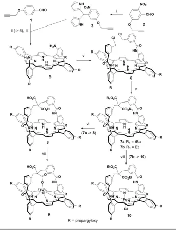
Scheme 1. (i) pyrrole (40 equiv.), TFA (0.1 equiv.), 51%; (ii) dry CH2Cl2, BF3-Et2O
(0.1 equiv.), 16h at RT, then DDQ, 34%; (iii) HCl:EtOH (25:1), SnCl2, 50°C, 48 h,
80%; (iv) 3-(chloromethyl)benzoyl chloride, dry CH2Cl2, Et3N, 0°C, 3 h, 97%. (v)
CH2(CO2Et)2 (10 equiv.), THF, EtONa, RT, 12 h, 80% or CH2(CO2tBu)2 (5 equiv.),
THF, tBuOK, RT, 8 h, 60%. (vi) concentrated HCl, THF, RT, 48 h, 60%. (vii) FeBr2,
2,6-lutidine, THF, RT, 36 h, silica gel column chromatography after air oxidation and HCl (1M) washing, (90%). (viii) THF, FeBr2, reflux overnight, 2,6-lutidine, 90%.
Results and discussion
Synthesis
The general synthetic pathway for porphyrin derivatives is presented in Scheme 1. The reaction sequence started with the synthesis of the propagyloxy-functionalized aromatic aldehyde 1 and 2. The reaction of 2 with an excess of pyrrole led to the 2-nitroaryldipyrromethane 3 which, condensed on aldehyde 1, was converted into porphyrin 4 whose nitro functions were reduced by the usual methods to obtain porphyrin 5. Reaction of the purified atropisomer of 5 with 3-chloromethyl benzoyl chloride furnished bis-picket porphyrin
6 which was treated in alkaline conditions with either diethyl
malonate or di-tert-butyl malonate to give rise to the strapped ligands 7a-b. The ester groups of porphyrin 7a (R1= tBu) were
cleaved by treatment with HCl (1 M) at room temperature for 48h leaving the propargyloxy groups unaffected and leading to porphyrin 8. Finally porphyrins 8 and 7b (R1= Et) were
metallated with iron (II) bromide in THF to give 9 and 10, respectively (see ESI for experimental details and characterization).
The X-ray structure of porphyrin 9 was solved (Fig. 1) and it established that one of the two carboxylic acid groups is coordinated to the ferric cation as its fifth ligand with a bond length for O1-Fe of 1.945 Å. The iron(III) cation is bound 0.512 Å out of the mean porphyrin plane (24MP) towards its fifth ligand. However, with this strap linked on two opposite meso positions (5, 15), it has been shown on a bis-strapped analogous complex that the coordination of the overhung carboxylic acid on the iron(II) cation was not possible.44 The porphyrin is saddle-shaped together with a significant ruffling as indicated by an average angle between the two pairs of opposed pyrroles of 20.24°. The W-shaped strap, disordered over two positions is almost perpendicular to the porphyrin plane (angle between the two mean planes of 84.28°).
Fig. 1 Oak Ridge thermal ellipsoid plot (ORTEP, 30% thermal ellipsoids)
representation (left) and apical rod view (right) of the X-ray structure of iron (III) porphyrin 9. Selected distances (Å) and angles (°): N1-Fe 2.060, N2-Fe 2.044, N3-Fe 2.051, N4-N3-Fe 2.041, O1-N3-Fe 1.945, (O2,O3) 2.498, (24MP, N3-Fe) 0.512, (24MP, strap plane) 84.28.
The synthesis of the hybrid MWNT/strapped porphyrin materials MWNT-FeP(9) and MWNT-FeP(10) is presented in Fig. 2. Purified MWNTs32 were dispersed in
N-methylpyrrolidone (NMP), then 9 or 10 were added and the mixture was gently sonicated and then let sit for 30 min. Then
a freshly prepared mixture of copper(I) chloride and N,N,N’,N’-tetramethylethylenediamine (TMEDA) was added and the reaction was stirred at room temperature for 24h under an atmosphere of oxygen. After reaction, the nanotube materials were purified by filtration through 0.2µm PTFE membrane and washed with NMP (to remove unreacted porphyrins), water, NH4Cl solution (to remove the copper catalyst) and then again
with water and NMP (see ESI).
Fig. 2 Schematic representation of the synthesis of FeP(9) and MWNT-FeP(10); i) CuCl, TMEDA, NMP, O2, RT.
Characterization
The nanotube hybrids were characterized by absorption, Raman and X-ray photoemission (XPS) spectroscopy while their morphologies were investigated by electronic microscopies (SEM and TEM). Finally, their ORR activity was studied using Rotating Ring-Disk Electrode (RRDE) at different pH.
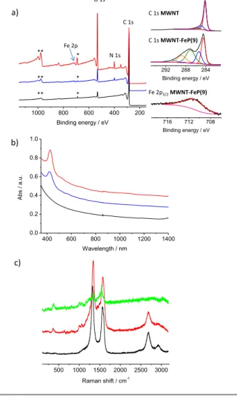
First XPS gives us qualitative information on the elemental composition of our hybrid materials. The XPS spectra of
MWNT, MWNT-FeP(9) and MWNT-FeP(10) are presented in
Fig. 3a; the peaks labelled (*) on the spectra are due to fluorine (F1s) arising from the PTFE supporting membrane and
the peaks labelled (**) are due to oxygen Auger lines (OKLL).
For MWNT, the spectrum shows only the presence of carbon and a bit of oxygen (coming from the oxidative purification treatment) whereas the spectra of FeP(9) and
MWNT-FeP(10) show the presence of nitrogen and iron coming from
the porphyrins. The high resolution spectra of the carbon (right part of Fig. 3a) for MWNT show mainly the contribution of sp2 carbon atoms of the nanotubes; the C1s spectrum of
MWNT-FeP(9) exhibit a very different pattern with
contributions at higher binding energy due to the presence of the organic materials (i.e., the porphyrins) around the nanotubes. XPS also permits to estimate the atomic concentration of iron: it is around 0.1 and 0.08 atomic % for
MWNT-FeP(9) and MWNT-FeP(10), respectively. Note that
these values are not representative because of the margin of error on the analysis; nevertheless they show that these
materials contain iron. The absorption spectrum (Fig. 3b) of
MWNT shows a strong absorption in the UV region and a
monotonic decrease of the absorption signal in the visible and NIR region. Conversely, the spectra of MWNT-Fe(9) and
MWNT-Fe(10) exhibit signals at ca. 425 nm with shoulder in
the 500-600 nm region arising from the Soret and the Q-bands of the porphyrins.
Fig. 3 a) XPS spectra of MWNT (black), MWNT-FeP(10) (blue) and MWNT-FeP(9)
(red); on the right deconvoluted XPS core level spectra of carbon C1s of MWNT
and MWNT-FeP(9) and iron Fe2p3/2 of MWNT-FeP(9). The signals labelled (*) and
(**) are due to fluorine from the PTFE membrane and the oxygen Auger lines, respectively; b) UV-Vis-NIR absorption spectra of MWNT (black), MWNT-FeP(10) (blue) and MWNT-FeP(9) (red); c) Raman spectra recorded with excitation at 532 nm of MWNT (black), MWNT-FeP(9) (red) and porphyrin 9 (green).
The Raman spectra of MWNT, MWNT-FeP(9) and Fe-porphyrin
9 taken as reference are shown in Fig. 3c. The spectrum of MWNT shows the typical first order graphical mode (G band)
at 1570 cm-1 and defect band (D band) at 1330 cm-1 as well as the second order 2D and D+G in the 2500-3000 cm-1 region. The iron porphyrin (green spectrum) exhibits several bands at 350 cm-1 and between 1000 and 1600 cm-1; these bands can be clearly identified in the spectrum of MWNT-FeP(9), in addition to the D, G, 2D and D+G bands, confirming the presence of the porphyrin on the nanotubes. Interestingly, we were not able to observe the characteristic bands of the triple bond at around
=
9 10 MWNT-FeP(9) MWNT-FeP(10) i 1000 800 600 400 200 Binding energy / eV 500 1000 1500 2000 2500 3000 Raman shift / cm-1 400 600 800 1000 1200 1400 0.0 0.2 0.4 0.6 0.8 1.0 A b s / a .u . Wavelength / nm C 1s MWNT C 1s MWNT-FeP(9) 716 712 708 Binding energy / eV Fe 2p3/2MWNT-FeP(9) C 1s N 1s O 1s * Fe 2p a) b) c) 292 288 284 Binding energy / eV * * ** ** **2100 cm-1 neither in the porphyrin nor in the functionalized nanotubes, even when Raman spectroscopy was performed with excitation at 476 nm (Fig. S1). By Infrared spectroscopy, very weak bands at 2115 cm-1 corresponding to the stretching band of the C≡C bonds were observed for FeP(9) and FeP(10) (Fig. S2); unfortunately, this band could not be observed in the nanotube hybrids certainly because they strongly absorb IR making the observation of weak peaks difficult.
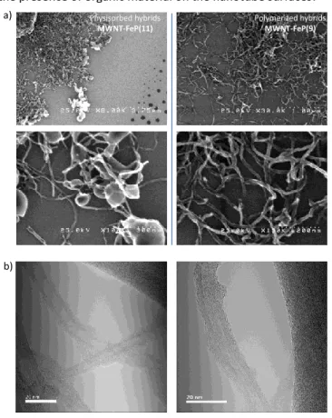
The nanotube/porphyrin hybrids were studied by scanning and transmission electron microscopy (SEM and TEM). SEM images are presented in Fig. 4a. In the physisorbed hybrid
MWNT-FeP(11) (left part), the images show that the porphyrins tend
to segregate and form bubbles of organic materials at the extremity of the nanotubes and dried drops on the silicon surface. This observation supports the fact that the interactions between the porphyrins and the nanotubes are quite weak and the two components can segregate in the catalytic inks. On the contrary, for the polymerized hybrid
MWNT-FeP(9), the nanotube surfaces appear homogeneous
with no aggregates detected (Fig. 4a, right part). So we believe that the porphyrin are exclusively located and homogeneously distributed on the nanotube surfaces. Unfortunately, the limited resolution of SEM does not permit to observe porphyrin coating. This was achieved owing to TEM analysis: the images of MWNT-FeP(9) (Fig. 4a and S3) show the presence of a thin layer of organic materials on the nanotubes. For comparison, TEM images of MWNT (Fig. S3) do not show the presence of organic material on the nanotube surfaces.
Fig. 4 a) SEM images MWNT-FeP(11) (left) and MWNT-FeP(9) (right); in the
physisorbed hydrid MWNT-FeP(11), the porphyrins tend to segregate; b) TEM images and representation of MWNT-FeP(9).
Oxygen reduction reaction activity
We now turn to the characterization of the ORR activity of the nanotube/porphyrin hybrids. As a reference material for ORR, we also prepared MWNT-FeP(11) in which iron (III) porphyrin
11 is simply adsorbed on the nanotube sidewalls (see structure
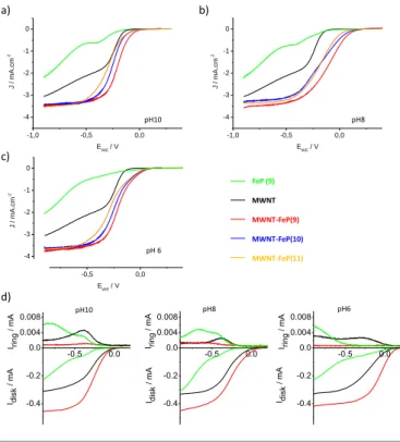
in ESI). Fig. 5 presents the electrocatalytic properties for the reduction of oxygen of the different components: MWNT, Fe-porphyrin 9, FeP(9), FeP(10) and
MWNT-FeP(11) at pH 10, 8 and 6 deposited on the Glassy Carbon (GC)
electrode recorded at 800 rpm; the complete cycles (from 0 to 2000 rpm) for all hybrids are given in Fig. S4-S6. All the curves correspond to the average (reduction and reoxidation) of the cyclic voltammetry curves. First of all, the RDE curves (Fig. 5a-c) show that the catalytic inks made by mixing the nanotubes with the porphyrins exhibit higher current density and lower overpotential (of about 0.1 to 0.25V depending on the pH) than porphyrins alone. The current density is related to the number of electrons involved in the reduction of oxygen. Thus, the increase of current density suggests that the nanotube/porphyrin catalytic inks permit to reduce oxygen via a process involving a higher number of electrons than catalytic the inks made only with iron porphyrins. The presence of the nanotubes is therefore extremely important to improve the ORR properties. We believe that it is due to the conductivity of the nanotubes which facilitates the access of the electrons to the catalytic centers. This result is not surprising since Rigsby
et al.45 demonstrated that the mesoscale environment around the catalyst (iron porphyrins) plays a crucial role on the resulting properties. It is also worth mentioning that MWNT (black curve) reduced oxygen with a lower overpotential and a higher current density than FeP 9. However, compared to the three MWNT/FeP hybrids, MWNT alone exhibit current densities of ca. 1 mA/cm2 lower (at −0.6V vs Ag/AgCl) than those of the hybrids. Indeed, it was found that at low potential carbon nanotubes reduce oxygen via a 2-electron process to give hydrogen peroxide.46
Fig. 5a-c also shows the comparison between the ORR activity of MWNT-FeP(11) (the reference in which Fe-porphyrin 11 is simply mixed with the nanotubes), MWNT-FeP(10) (the polymerized nanotube-porphyrin hybrid in which the proton relay is absent) and MWNT-FeP(9) (the polymerized nanotube-porphyrin hybrid containing proton relays). At all the considered pH, the polymerized hydrids MWNT-FeP(9) show slightly better properties than the hybrids in which the porphyrins are simply mixed with the nanotubes
(MWNT-FeP(11)). A possible explanation of this observation comes
from SEM images. Indeed, one can see that in MWNT-FeP(11) (Fig. 5a – left part), the porphyrin tends to segregate and form drop-shaped aggregates on the nanotubes. Conversely, in the polymerized hybrids, the porphyrin seems better dispersed along the nanotubes. This result suggests that the catalytic activity of the porphyrins is better when there are in close contact with the nanotube surfaces. In the case of the polymerized hybrids, the comparison between MWNT-FeP(9) and MWNT-FeP(10) does not permit to conclude that the presence of proton relays has a significant influence on the
Physisorbed hybrids MWNT-FeP(11) Polymerized hybrids MWNT-FeP(9) a) b)
ORR activity of the strapped porphyrins. Indeed even at pH 6, the curves are very similar and only a slight difference of 20-30 mV of the reduction potential is observed. The close proximity of the proton donor group to the iron center does not seem to be a prerequisite to influence significantly the electrocatalytic properties. The presence of Nafion in the mixture likely ensures the availability of proton close to the reaction center.
Fig. 5 RDE curves (rotation rate of 800 rpm) recorded for ORR in O2-saturated
phosphate buffer solutions at pH 10 (a), pH 8 (b) and pH 6 (c) (scan rate = 5 mV s -1
, room temperature) on GC with predeposited FeP (9) (green), MWNT (black),
MWNT-FeP(11) (orange), MWNT-FeP(10) (blue) and MWNT-FeP(9) (red). d)
RRDE measurements of oxygen reduction (negative current) and hydrogen peroxide oxidation (positive current) for MWNT (black), FeP (9) (green), and
MWNT-FeP(9) (red) at pH 10, pH 8 and pH 6 (from left to right) in O2-saturated
phosphate buffer solutions. The ring electrode was polarized at 0.8 V vs Ag/AgCl. Rotation rate: 400 rpm; scan rate: 5 mV s-1.
Fig. 5d shows the RRDE curves registered at a rotation rate of 400 rpm for MWNT, FeP (9) and MWNT-FeP(9) at various pH. The number of electrons involved in the reduction of oxygen for MWNT-FeP(9) and for the porphyrin FeP (9) and the
MWNT used as references was determined using the current
detected at the ring electrode using Eq. 1.47
𝑛 =
4𝐼𝑑𝑖𝑠𝑘𝐼𝑑𝑖𝑠𝑘+𝐼𝑟𝑖𝑛𝑔𝑁𝐶
(Eq. 1)
NC, the collection coefficient (0.2) was determined using the
one-electron Fe(CN)63–/Fe(CN)64– redox couple and Idisk and Iring
were determined on the RRDE curves. The numbers of electrons involved in the reduction as well as the onset potentials for the reduction are collected in Table 1. From the ring current curves of Fig. 5d, one can observe directly that the reduction of O2 is accompanied by the production of hydrogen
peroxide both for MWNT and FeP (9). Conversely, for
MWNT-FeP(9), almost no production of H2O2 is detected.
Table 1. Onset potential for the reduction of oxygen and number of
electrons involved in the reduction at -0.6V vs Ag/AgCl. Onset potent. pH 10 (V) n e− Onset potent. pH 8 (V) n e− Onset potent. pH 6 (V) n e− FeP (9) -0.20 3.29 -0.25 3.32 0.04 3.69 MWNT -0.12 3.78 -0.13 3.90 0.03 3.85 MWNT-FeP(9) -0.07 3.96 -0.04 3.95 0.10 3.97
The onset potential for ORR of the hybrid materials is found to be -0.07, -0.04 and 0.10 V vs Ag/AgCl from pH 10 to pH 6 that means 0.13, 0.16 and 0.30V vs NHE since the potential of Ag/AgCl reference vs NHE is 0.198V. The thermodynamic potentials for the reduction for the reduction of oxygen are ca. 0.63V at pH 10, 0.75V at pH 8 and 0.87V at pH 6. This result shows that our hydrid materials present a quite large overpotential of ca. 0.5-0.6V compared to the thermodynamic potential for the reduction of oxygen.
Conclusions
We described the synthesis of new strapped iron(III)-porphyrin and the subsequent formation of hybrid materials with carbon nanotubes for oxygen reduction reaction purposes. The electrocatalytic activity of porphyrins bearing carboxylic groups expected to act as proton relay during the reduction of O2 was studied and compared with their direct precursor
containing ethyl ester groups. First, the hybrid nanotube/porphyrin materials exhibit much better ORR activity than the two components (nanotubes and Fe(III)-porphyrins) alone as the nanotube/porphyrin hybrids reduce oxygen in water via a 4-e−. Second, no significant improvement of the ORR activity due to the presence of proton relay in the hybrids (especially at pH 6) was observed. The presence of Nafion in the catalytic inks ensures a sufficient supply of protons during the reaction. This second observation underlines the essential need of control reactions with reference catalysts to probe the actual influence of additional groups on the activity of such catalysts.
Finally, it is worth mentioning that the results obtained here are difficult to compare to literature since the conditions used to characterize the properties are never the same from one report to another. Furthermore, it was suggested that the environment of the catalyst at the mesoscale play a crucial role on the performances.45 The hybrids presented here exhibit overpotential for the reduction of oxygen of ca. 0.5-0.6V compared to the thermodynamic potential.
Conflicts of interest
There are no conflicts to declare.
Acknowledgements
-0.5 0.0 0.004 0.008 0.012 0.016 0.020 I ring / mA -0.4 -0.2 0.0 I disk / mA pH8 -0.4 -0.2 0.0 I disk / mA -0.5 0.0 0.004 0.008 0.012 0.016 0.020 I ring / mA pH6 -1,0 -0,5 0,0 -4 -3 -2 -1 0 J / m A .c m -2 E WE / V pH 6 -1,0 -0,5 0,0 -4 -3 -2 -1 0 J / m A .c m -2 E WE / V FeP (9) MWNT MWNT-FeP(9) MWNT-FeP(10) MWNT-FeP(11) pH10 -1,0 -0,5 0,0 -4 -3 -2 -1 0 J / m A .c m -2 E WE / V pH8 a) b) c) -0.5 0.0 0.004 0.008 0.012 0.016 0.020 I ring / mA -0.4 -0.2 0.0 I disk / mA pH10 d)Please do not adjust margins
This work was also supported by the JST-ANR program TMOL “Molecular Technology” project MECANO (ANR-14-JTIC-0002-01) and by a public grant overseen by the French National Research Agency (ANR) as part of the “Investissements d’Avenir” program (Labex NanoSaclay, reference: ANR-10-LABX-0035). The authors thank M. Bouhier from NIMBE/LAPA, CEA-Saclay for help in Raman measurements and Prof. K. Oohora from Osaka University for the nanotube/porphyrin artworks.
Notes and references
1 E. S. Andreiadis, P.-A. Jacques, P. D. Tran, A. Leyris, M. Chavarot-Kerlidou, B. Jousselme, M. Matheron, J. Pécaut, S. Palacin, M. Fontecave and V. Artero, Nat. Chem., 2013, 5, 48.
2 C. G. Morales-Guio, L.-A. Stern and X. Hu, Chem. Soc. Rev., 2014, 43, 6555.
3 Y. Xu, M. Kraft and R. Xu, Chem. Soc. Rev., 2016, 45, 3039.
4 J. Wang, F. Xu, H. Jin, Y. Chen and Y. Wang, Adv. Mater., 2017, 29, 1605838.
5 A. Eftekhari, Int. J. Hydrog. Energy, 2017, 42, 11053.
6 A. Le Goff, V. Artero, B. Jousselme, P. D. Tran, N. Guillet, R. Métayé, A. Fihri, S. Palacin and M. Fontecave, Science, 2009, 326, 1384.
7 N. Coutard, N. Kaeffer and V. Artero, Chem. Commun., 2016, 52, 13728.
8 E. S. Davydova, S. Mukerjee, F. Jaouen and D. R. Dekel, ACS Catal., 2018, 8, 6665.
9 M. W. Kanan and D. G. Nocera, Science, 2008, 321, 1072.
10 F. M. Toma, A. Sartorel, M. Iurlo, M. Carraro, P. Parisse, C. Maccato, S. Rapino, B. Rodiguez Gonzalez, H. Amenitsch, T. Da Ros, L. Casalis, A. Goldoni, M. Marcaccio, G. Scorrano, G. Scoles, F. Paolucci, M. Prato and M. Bonchio, Nat. Chem., 2010, 2, 826.
11 X. Li, X. Hao, A. Abuduka and G. Guan, J. Mater. Chem. A, 2016, 4, 11973.
12 A. Morozan, B. Jousselme and S. Palacin, Energy Environ. Sci., 2011, 4, 1238.
13 F. Jaouen, E. Proietti, M. Lefèvre, R. Chenitz, J.-P. Dodelet, G. Wu, H. T. Chung, C. M. Johnston and P. Zelenay, Energy Environ. Sci., 2011, 4, 114.
14 D.-W. Wang and D. Su, Energy Environ. Sci., 2014, 7, 576.
15 M. Shao, Q. Chang, J.-P. Dodelet and R. Chenitz, Chem. Rev., 2016, 116, 594.
16 W. He, Y. Wang, C. Jiang and L. Lu, Chem. Soc. Rev., 2016, 45, 2396. 17 V. R. Stamenkovic, B. Fowler, B. S. Mun, G. Wang, P. N. Ross, C. A.
Lucas and N. M. Markovic, Science, 2007, 315, 493. 18 M. K. Debe, Nature, 2012, 486, 43.
19 J. P. Collman, L. Fu, P. C. Herrmann and X. Zhang, Science, 1997, 275, 949.
20 J. P. Collman, N. K. Devaraj, R. A. Decréau, Y. Yang, Y.-L. Yan, W. Ebina, T. A. Eberspacher and C. E. D. Chidsey, Science, 2007, 315, 1565. 21 D. Ricard, B. Andrioletti, M. L'Her and B. Boitrel, Chem. Commun.,
1999, 1523.
22 F. Melin, A. Trivella, M. Lo, C. Ruzié, I. Hijazi, N. Oueslati, J. A. Wytko, B. Boitrel, C. Boudon, P. Hellwig and J. Weiss, J. Inorg. Biochem., 2012,
108, 196.
23 W. Zhang, W. Lai and R. Cao, Chem. Rev., 2017, 117, 3717. 24 J. P. Collman and S. Ghosh, Inorg. Chem., 2010, 49, 5798.
25 D. Ricard, A. Didier, M. L'Her and B. Boitrel, ChemBioChem, 2001, 2, 144.
26 D. Ricard, M. L'Her, P. Richard and B. Boitrel, Chem. Eur. J., 2001, 7, 3291.
27 J. Rosenthal and D. G. Nocera, Acc. Chem. Res., 2007, 40, 543. 28 J. Rosenthal and D. G. Nocera, in Progress in Inorganic Chemistry, ed.K.
D. Karlin, John Wiley & Sons, Inc., 2007, ch. Chapter 7, pp. 483-544.
29 R. McGuire Jr, D. K. Dogutan, T. S. Teets, J. Suntivich, Y. Shao-Horn and D. G. Nocera, Chem. Sci., 2010, 1, 411.
30 C. T. Carver, B. D. Matson and J. M. Mayer, J. Am. Chem. Soc., 2012,
134, 5444.
31 A. Morozan, S. Campidelli, A. Filoramo, B. Jousselme and S. Palacin, Carbon, 2011, 49, 4839.
32 I. Hijazi, T. Bourgeteau, R. Cornut, A. Morozan, A. Filoramo, J. Leroy, V. Derycke, B. Jousselme and S. Campidelli, J. Am. Chem. Soc., 2014, 136, 6348.
33 P.-J. Wei, G.-Q. Yu, Y. Naruta and J.-G. Liu, Angew. Chem. , Int. Ed., 2014, 53, 6659.
34 I. Kruusenberg, L. Matisen, Q. Shah, A. M. Kannan and K. Tammeveski, Int. J. Hydrog. Energy, 2012, 37, 4406.
35 K. Elouarzaki, A. Le Goff, M. Holzinger, J. Thery and S. Cosnier, J. Am. Chem. Soc., 2012, 134, 14078.
36 Z. Wang, H. Lei, R. Cao and M. Zhang, Electrochem. Acta, 2015, 171, 81. 37 H. Jia, Z. Sun, D. Jiang and P. Du, Chem. Mater., 2015, 27, 4586. 38 H. Jia, Z. Sun, D. Jiang, S. Yang and P. Du, Inorg. Chem. Front., 2016, 3,
821.
39 X. Wang, B. Wang, J. Zhong, F. Zhao, N. Han, W. Huang, M. Zeng, J. Fan and Y. Li, Nano Res., 2016, 9, 1497.
40 R. Venegas, F. J. Recio, J. Riquelme, K. Neira, J. F. Marco, I. Ponce, J. H. Zagal and F. Tasca, J. Mater. Chem. A, 2017, 5, 12054.
41 R. Venegas, F. J. Recio, C. Zuñiga, M. Viera, M.-P. Oyarzún, N. Silva, K. Neira, J. F. Marco, J. Zagal and F. Tasca, Phys. Chem. Chem. Phys., 2017,
19, 20441.
42 X. Yan, X. Xu, Q. Liu, J. Guo, L. Kang and J. Yao, J. Power Sources, 2018,
389, 260.
43 A. S. Hay, J. Org. Chem., 1962, 27, 3320.
44 I. Hijazi, T. Roisnel, M. Fourmigué, J. Weiss and B. Boitrel, Inorg. Chem., 2010, 49, 3098.
45 M. L. Rigsby, D. J. Wasylenko, M. L. Pegis and J. M. Mayer, J. Am. Chem. Soc., 2015, 137, 4296.
46 I. Kruusenberg, N. Alexeyeva and K. Tammeveski, Carbon, 2009, 47, 651.
47 R. Zhou, Y. Zheng, M. Jaroniec and S.-Z. Qiao, ACS Catal., 2016, 6, 4720.