The Different Levels of Intent Specifications: Analysis and Guidelines on Tracing
by
William J. Meldndez Diaz
Submitted to the Department of Electrical Engineering and Computer Science
in Partial Fulfillment of the Requirements for the Degree of
Master of Engineering in Electrical Engineering and Computer Science at the Massachusetts Institute of Technology
May 23, 2001 N
i
y7- 0Copyright 2001 William J. Meldndez Diaz. All rights reserved.
The author hereby grants to M.I.T. permission to reproduce and distribute publicly paper and electronic copies of this thesis
and to grant others the right to do so.
Author
-,Aiepartment of4l66tric4afEgIneering and Computer Science
May 23, 2001
Certified by.
Professor Nancy Leveson Thesis Supervisor
Accepted by
Arthur C. Smith Chairman, Department Committee on Graduate Theses
OF TECHNOLOGY
JUL11
2001
The Different Levels of Intent Specifications: Analysis and Guidelines on Tracing
by
William J. Mel6ndez Diaz
Submitted to the Department of Electrical Engineering and Computer Science in Partial Fulfillment of the Requirements for the Degree of
Master of Engineering in Electrical Engineering and Computer Science at the Massachusetts Institute of Technology
May 23, 2001
Abstract
The increase in the use of computers to control complex systems in which a failure can result in the loss of life and property has led to new safety issues, particularly when control processes are the joint responsibility of humans and machines. Intent specifications provide a clear, step-by-step
process to developing systems allowing safety and human factors issues to be integrated into the design from the early stages of development. Additionally, the levels of an intent specification are tied to each other through tracing, which links design and implementation decisions to their underlying reasons and vice versa. An intent specification for the minimum safe altitude warning
(MSAW)
function of a new air traffic control system was successfully created, and it is compared to the function's existing specification documents. Furthermore, described is a step-by-step guide to tracing between the levels of intent specifications as well as guidance on distinguishing between what type of design and implementation information goes into each particular level.Thesis Supervisor: Nancy G. Leveson
Table of Contents
INTRODUCTION
7RELATED WORK
11
BACKGROUND
13TEST CASES
19STANDARD TERMINAL AUTOMATION REPLACEMENT SYSTEM (STARS) 19
MATTERHORN BOBSLED RIDE 20
ANALYSIS
23CURRENT STARS/MSAW DOCUMENTATION 23
DISTINGUISHING THE LEVELS OF INTENT SPECIFICATIONS 26
TRACING 27
CONCLUSION
39FUTURE WORK
41APPENDIX A
-
MSAW SOFTWARE DESCRIPTION
43APPENDIX B
-
MSAW INTENT SPECIFICATION
51LEVEL I - SYSTEM PURPOSE 51
LEVEL 11 - SYSTEM DESIGN PRINCIPLES 64
LEVEL III - BLACKBOX BEHAVIOR 78
Introduction
Over the course of the past few decades, a technological boom has occurred in the field of computers.
They
have become increasingly more powerful, and their usefulness has provided humans with a tool that can be used in a wide range of applications. Computers have provided humans the ability to design, build and manage a wider range of systems with increased complexity. This increased complexity has led increasingly to the use of computers to control complex systems. Great things have come from this use of computers, such as the ability to produce better, more useful aircraft and space systems. However, a down side to automating the control processes of systems where a failure can result in the loss of life and property is that safety might be affected. Failure does not necessarily come from software errors. Given the complexity of a system, failures usually come from incomplete requirements or erroneous requirements. Furthermore, the vastmajority of systems are not fully automated. Rather, they utilize humans to manage some tasks and to mitigate and/or resolve problems.
This
fact creates further problems because the operator andthe automation might not be in sync. In other words, the operator thinks the system is doing one thing, while the automation is doing something else. Thus, understanding of the system processes and of the interfacing between the automation and operator are also of crucial importance.
To solve these issues, safety needs to be considered from the very beginning stages in the design of a system. When doing this, requirements can be drawn up to eliminate or minimize possible hazards. Afterwards, design decisions are made to satisfy these requirements and ensure a high-level of safety. If a procedure such as this is not followed, changing the design requirements at a later stage to solve a safety issue that could have been taken into consideration at the beginning proves to be very costly, and sometimes comers are cut (e.g. safety) to not undertake those costs. Failure to do this also adds costs due to time spent changing the system, and the quality of the
design might be degraded. When taking safety into consideration early, requirements for the system and the human/computer interface can prevent, to a certain extent, any hazardous conditions in the system, and therefore limit any accidents that might occur. Additionally, all people that will need to understand the system should do so in the same manner. For example, the operators need to know how the system works exactly the same way as the designers intended it. When the models of the system are the same for everybody involved, problems can be prevented more easily because all parties understand the system in the same manner. This is where intent specifications and the Specifications Tools and Requirements Methodology (SpecTRM) requirements language Prof. Nancy Leveson has developed play a role.
Intent specifications are meant to provide system and software engineers a way to perform "requirement analysis, software design, review for correctness, debugging, maintenance and evolution, and reengineering" [1]. Intent specifications help designers be in sync with builders, as well as builders with maintainers or operators. In other words, they "help the designer, builder, tester, debugger, or maintainer understand the system well enough to create a physical form, or to find problems in or change the physical form" [1].
Secondly, SpecTRM is a formal specification language under development that can be used to model a system, and to analyze it for completeness. It is also intended to be readable to all parties involved in the system, which allows for everybody to have a clear model of the system at hand. Prof. Leveson's Safeware Corporation is developing software that would allow users to specify the
requirements using the SpecTRM-RL form, to execute the specification to check it for completeness among other things. Both of these, intent specifications and SpecTRM, are designed to be human-centered, that is, the fact that humans will be using and operating the system is of primary concern at all stages of development. In combination, these are a powerful mix that has the potential to improve the world of system design and implementation.
The research for this particular project involves an analysis of SpecTRM, which was performed using the STARS ATC Minimum Safe Altitude Warning (MSAW) subfunction as an example. MSAW detects whether an aircraft is flying below a safe altitude for the area. This subfunction was modeled using the SpecTRM Requirements Language.
The MSAW function of
STARS provides a good test case because a failure in such a function can lead to the loss of life and property. It also includes a human/machine interface between the function and the air traffic controller. Additionally, as part of the analysis, the SpecTRM model for the Matterhorn BobsledRide developed for the System and Software Safety class (16.358), and the process leading to the model, was used.
The project described herein involves two main issues in addition to providing an analysis of
MSAW and its current documentation. The main part of the project involved analyzing the current
tracing techniques used in intent specifications for linking the different elements to each other. The second part of the project involved a problem that has been encountered in the use of intent specifications. The problem is that people encounter some trouble distinguishing between the five levels that encompass these specifications, primarily determining what goes between the second and fourth levels (See Background section for descriptions of the different levels of intent
specifications).
This
project, in addition to analyzing and modeling the two systems mentioned above, explores this problem and attempts to further explain how a person can utilize intent specifications without having as much trouble. The project provides a discussion on performing analyses and dividing the information of a current system into the different levels of intentspecifications, or defining and creating level by level a new system without going into unnecessary detail. With a clear knowledge of the differences between the levels, the task of tracing is expected to become easier because there is no interleaving of information, no redundancy between the levels. That way people will clearly get the "Whys?" and "Hows?" of the system being specified. Currently,
the five levels of the intent specifications are clearly defined in theory as part of previous work by Prof. Leveson and her colleagues, and there are several examples of them being applied to real systems, but a more general and practical view of the specifications is a good next step that will hopefully lead to even more solid and robust intent specifications. In this manner, anybody would be able to use the specifications to their advantage.
Related Work
Professor Nancy Leveson has worked on several proofs of concept for her modeling language SpecTRM-RL. The most significant one was the intent specifications created for the Traffic Collision and Avoidance System (TCAS) II, which was done with Jon Damon Reese [3].
TCAS II provides collision avoidance help for aircraft by interrogating the transponders of aircraft
in its vicinity. If the aircraft has the potential to collide with the other aircraft, or it is predicted to do
so in the near future, TCAS II would alert the pilot of the fact. TCAS II outputs two types of
advisories, a preventive advisory in the case there are many aircraft in the vicinity telling the pilot not to climb, descent or adjust vertical speed, and a corrective advisory telling the pilot to climb, descent, etc., to ensure a safe separation between aircraft in the case of an imminent hazard.
A complete example of intent specifications was created for TCAS II encompassing the
different levels mentioned above. From this work several papers were written to further develop the modeling language as well as the intent specification methodology as defined by our research. See [3] for the intent specifications.
Additionally, work has been performed on systems such as the Center-TRACON Automation System (CEAS) and Eurocontrol (Europe's ATC).
Background
In its most basic form, intent specifications are "an approach to building human-centered specifications" [1]. Given the complexity of today's engineered systems, human operators and maintenance technicians need to be a primary focus when developing any system because the complexity of these systems, particularly those where automation takes on a primary role, can lead to new kinds of human error that are not dealt with by the automation. These errors are usually due to differences between the state of the system and the perceived state of the system by the operator. This confusion can lead to wrong decisions on the part of the operator. These mistakes, which can lead to deadly accidents, are frequently attributed to human error when in reality they are caused by
flaws in the overall system design. Therefore, system engineering nowadays needs to be human-centered, not just technology-centered.
Intent specifications take into consideration the psychological processes humans go through when performing a task or solving a problem using the specifications of the system. Intent
specifications include the "Whys" and "Hows" of the system so that users understand the processes behind that which he or she must control or oversee. It "captures the meaning and assumptions behind the problem-solving process modeled in the system" [2]. Given a clear understanding of the system, its true intentions and the specifics of how it works, users will have a clear model of the system, will be able to handle their tasks more easily and be able to mitigate and resolve any problems they might encounter with more precision.
An intent specification encompasses four key elements, which provide its foundation. First is the process of the system. Any system contains a process, which is the underlying manner in which a system is developed from its early stages to its full implementation. The "process provides a logical structure for problem solving" [1]. All parts of the development process, as stated before, are to be
mapped to each other, thus tracing hazard analysis results to system and software requirements to design decisions to how they were implemented in the actual system.
Another key facet of intent specifications is that they take into consideration issues revolving around the interactions between humans and the machine. The interface between the system and any human operator is to be carefully designed and implemented to satisfy any requirements brought about in the hazard analysis of the system. Therefore, given the difficulties of integrating computer and human control, features can be implemented in the system with the intent specifications methodology that can prevent human error.
The next three elements of intent specifications are what separate them, in a way, from the commonly used specification methodologies used in industry and government. These elements are content, structure and form. They are important because they can deal with the psychological processes people go through when looking through specifications, and can improve readability so that everybody can have a clear understanding of the system, and thus prevent any problems that might result from misinterpretations.
Content deals with what is contained within the system, and what needs to be presented at each stage of development. Inputs, outputs, system boundaries, and the system environment are specified. Additionally, content should be complete, presenting the system clearly in its entire form.
Third, structure is the way the content is organized. The structure should present the information thoroughly, clearly and in a coherent manner for the user can carry on with his problem-solving task. All information on a system should not be hard to find, so organization is crucial. Intent specifications, as defined by our research, structure information into five hierarchical levels as explained below.
Last but not least, form "is the presentation of the content to the user in the specified structure". Every system to be developed will require a specific notation and language for its
description. This notation and language used needs to be addressed with respect to human
perceptual and cognitive capabilities so that they are usable by the user for his/her problem-solving task.
Through these four key elements, intent specifications provide a way to build systems that can easily be changed since all implementation decisions are traced to design decisions and
requirements, which in turn are traced to hazards through hazard analysis. So, if a requirement needs to change, people will know what parts of the system the changes will affect, and re-validation of requirements is easier. The ability to easily change system requirements is beneficial to systems with properties such as safety and security because they are of primary importance
in
many systems, and they must be built in from the beginning of the development process, not afterwards. Through intent specifications, these qualities can be tracked throughout the design process from its beginning, providing a way to include these properties without as much cost. Clear traceability between all these stages of development simply makes the evolution of a system efficient.Intent specifications, as defined by our research, consist of dividing the development of a system into five different levels. Design and implementation decisions at each level are mapped to the goals, requirements and constraints they were conceived to satisfy. This is done throughout all the levels. Vice versa, high-level requirements are traced down to the implementation, or physical
form. As proof of concept, Prof. Leveson worked out the intent specifications of the Traffic Collision and Avoidance System II (TCAS II) [3]. The different levels and their description follow (emphasis is given to the first three levels):
+ Level I, System Purpose: The first level of the intent specifications encompasses the purpose of the system. In this level, the system and its history are described as well as its
example, as part of the environment one can include the interface, the operator and the setting in which the system will operate. With a clear picture of the environment, the boundaries of the system are drawn, which will ease its development. In addition, and extremely important, the first level includes a hazard analysis of the system. With a thorough understanding of the hazards and their causes, a system engineer will then derive high-level goals, requirements, and constraints for the system, software, operator and interface among others. These requirements and constraints are used to mitigate the hazards that are inherent in the system, providing a way to make them minimal or non-existent. Any assumptions related to the system, its conditions and the environment are also documented in this level so as to provide a clear understanding of the reasons why some design decisions were made in the lower levels.
* Level II, System Design Principles: The basis of level two is the design of the
system itself, and the description of all the system design principles. System engineers take all the requirements and constraints of the first level and make design decisions that satisfy these
requirements, or minimize any hazard that may come from not fully satisfying it. Included in this level is the logic and algorithms that drive the functions of the system, but only taking into consideration inputs and outputs, which are described in this level. The logic and algorithms
describe what input combinations are required for all outputs that the system will contain, never the inside workings of the system.
The
interface design is also part of this level, which must also satisfy the interfacerequirements derived from the hazard analysis in the first level. Yet another part of this level is the testing and validation of the design. Validation of requirements is essential to the next stage of
potential hazards. Still, this portion of the level is usually system specific, which may include, but is not limited to, simulations and experiments.
* Level III, Blackbox Behavior: The third level analyzes the black box behavior of
the system as specified by the logic and algorithms of the second level. All of the components of the system are described in terms of inputs and outputs, and the interfaces between these components. This level also includes the human components of the system. The behavior of the system is
described "only in terms of externally visible variables, objects, and mathematical functions" [1]. These components can be built using hardware or software, and such decisions are usually made in the lower levels, if they have not been made yet. Having such a blackbox behavior available for the system, without having implemented it yet, allows for the testing of the requirements, thus making sure they are correct, unambiguous and complete for the system being developed. If a system has been implemented already, it is costly to modify it due to changes in requirements. Doing such testing at this stage allows system engineers to add, modify and delete requirements as needed without the added monetary, resource and time costs of having to change any implementation.
This level can also
include
things like operator tasks and procedures, descriptions of the interfaces and the message formats, as well as the specific testing requirements for the system.+ Level IV, Physical and Logical Design Representations: This level contains the
design representation of the system. It contains information about the physical and logical implementation of the components, usually in a language very familiar to software and hardware engineers. This level contains information such as specific software design, and the design of other components. Not all of the information in this level can be traced to the upper levels given that it allows the implementers to design the actual system with performance enhancing features that are
not required for the safe operation of the system. Other examples are the decision to use a specific communications protocol over another or the decision to use C instead of Java. "Knowing that these decisions are not linked to higher level purpose is important during software maintenance and evolution activities" [1].
This
level can also include operator manuals, human-computer interface design specification (e.g. the actual screens the operator sees and its options for operation), and verification requirements for those design decisions made at this level.* Level V, Physical Realization: The last level is the actual physical representation of
the system, which includes, but is not
limited
to, "the software itself, hardware assembly instructions, [and] training requirements (plan)" [1].As explained before, all of these levels are connected through tracing. All of the
requirements of the first level will trickle down to the lower levels until they are fully satisfied. For example, a requirement may be eliminated altogether via a general design decision in the second level. On the other hand, it might be dealt with through the design, modeled in a black box form, and then coded to satisfy the requirement. With this method, a reviewer or any other person will be able to work through the specification document with relative ease because of this tracing, and be able to draw the intentions of every decision along the way, with the possible exception of
Test Cases
This section explains in detail the test cases used in this project. Being the main test case, STARS goes into more depth than the Matterhom Bobsled Ride, which is used as an additional example. These two test cases give us different perspectives on intent specifications. MSAW was conceived in a backwards approach, from already existing documents, while the Matterhorn was conceived from scratch.
Standard Terminal Automation Replacement System (STARS)
STARS is a project undertaken by Raytheon Corporation to provide an upgrade to air traffic control automation systems. STARS provides automation to support air traffic control functions at
FAA Terminal Radar Approach Control (TRACON) and DOD Terminal Control regions [4].
STARS will fully replace the current air traffic control system after extensive testing for reliability and safety [4]. STARS is currently deployed in two sites and no major problems have been reported as of this moment [8]. Human air traffic controllers will use STARS to perform ATC functions as defined by the FAA Handbook 7110.65 named "Air Traffic Control", which includes, but is not limited to, radar separation, processing handoffs between controllers, and checking for conflicts and minimum safe altitude violations [4].
Although some of the functions of STARS were developed fully by Raytheon, portions of it
came from commercially available software as well as from Non-Developmental Item (NDI) ATC automation systems that have been fielded in other nations [4]. Many players have been involved in the design and implementation of the STARS systems. The FAA provides the key high-level
requirements for the system, and Raytheon then carried out and implemented the system to satisfy those requirements. There was no specific process to deal with human factors in the development of
STARS, even while the FAA provided a lot of input. Additionally, although controllers and other people involved in the daily operations of an air traffic control system participated in this
development, their feedback was not sought or heard at different points in the development process. This fact led to several late changes in the system because it was not up to the standards controllers wanted the system to be, particularly the interface requirements. Furthermore, there was not much time dedicated to human usability testing. However, in the end, the controllers requirements for the systems were satisfied, which cleared the way for its deployment as part of the testing phase. [8]
The
Minimum Safe Altitude Warning (MSAV) subfunction of STARS will be used as a test case. This module checks whether an aircraft has flown below an altitude in which it can collide with an object in the environment, such as a mountain or building. MSAW also checks for minimum safe altitude issues when the aircraft is in a landing approach. An extensive description of the MSAW software design is in Appendix A.As part of the overall STARS/SERL project, the Conflict Alert and Sector Handoffs
subfunctions are also being modeled. Please refer to ... for these models.
Matterhom Bobsled Ride
The
Matterhorn Bobsled Ride is a replica of the Swiss Matterhorn Mountain. It was constructed in California by Disney and provides a fun attraction for Disney park goers. The ride takes passengers up the mountain in specially made cars, and then they ride down the mounting driven only by gravity.As part of the System and Software Safety class of the Spring 2001 academic term, students were asked to design this ride after only being given a basic description of the ride. Students went through the intent specifications process, level by level, down to the third level, blackbox behavior.
system given the complexity and amount of time required to develop such a ride from scratch. Additionally, students had to design the control interface.
A number of safety issues were addressed as part of the development of this replica and that
is why the lessons learned while performing this task provide a good deal of information for this project. For example, the control system was designed to maintain the cars at a safe distance from each other. A collision can result in injury, or even death, for guests. Therefore, ensuring that cars are kept at a safe distance by designing in this property from the beginning of the development process is efficient and cost effective.
Analysis
Current STARS/MSAW Documentation
Before talking about the results of applying intent specifications to the MSAW function of the STARS systems, the actual specifications of the system must be analyzed in more detail. Raytheon provided two major documents on the system, which provided the vast majority of the information needed to evaluate the system and understand it. These documents are [4] and [5].
The way these specifications have been made had many strengths. The top requirements for the system were clearly defined and easy to read. These appeared in [4] and was each listed with a relevant heading such as Altitude Source for those requirements that dealt with what wiln be
providing the data on which to detect low altitude violations. These provided a pretty clear, concise starting point in the development of the system. For the intent specifications created for MSAW, these high-level system requirements were used as such in the first level (See Appendix B 4 Level I
4 System Requirements).
Other parts of the specifications, however, were not as clear, particularly the reasons behind the many design and implementation decisions.
The
majority of the reasons and assumptions behind the system design principles seem to have vanished in the years since the FAA specified MSAW through the NAS-MD-644 [7]. Raytheon followed the NAS-MD-644 in its design andimplementation of MSAW. When asked questions about certain of the functions and ways MSAW was implemented, such as the Windows Processing section (See Appendix A - Fine MSAW Filter
+
Window Processing), Raytheon engineers said to look at the NAS-MD-644. Nevertheless, all the NAS-MD-644 contained was information as to what MSAW must do and the principles behind the functional algorithms, not the reasons behind them. A lot of the intentions, assumptions andresult in the loss of life and property, everything must be stated in a clear way to make the
specifications complete. Different people will draw different conclusions when presented with the same information, so it is crucial that reviewers as well as maintainers of the system be able to know the why's and how's of the system. Although work still needs to be done in its full development, an intent specification provides this critical aspect. Therefore, inclusion of all relevant information is a point to be reconsidered in a full specification of MSAW.
Another important point is regarding inputs to the system. The SRS document [5] provides information on the blackbox behavior of the system, but some of the inputs are ambiguous in the sense that it is hard to figure out their necessary descriptive information.
The
SRS includes alist
of variables (which include the different inputs) in a form that is used inside the code (i.e. FPData,MSAWCA Parms, switchovermessage), and there is no exact description of the variables. So, if
there is any document describing these variables in detail, since there is nothing to link the SRS to such document, a reader will be left with questions that can be easily answered through Level III of an intent specification. Indeed some details can be extracted from reading the SRS, but it is no substitute for a clear, separate description of each input variable, or any other variable for that matter. See [10] for more information on the way intent specifications specify inputs and variables.
The outputs have similar issues as those of the inputs.
One key aspect of the research performed by Prof. Nancy Leveson is the fact that most system errors are in the requirements and not in the actual software. That is the reason why
completeness in requirements is a crucial step before the actual software design and implementation of a system. The first three levels of an intent specification provide a way to validate requirements before the software design and implementation commences, thus providing a less costly path in the case an error in the requirements is found. Once implementation begins, it is often harder to do this. Additionally, only specifying the system in terms of inputs and outputs initially provides
implementers with the freedom to build the guts of it as they see fit, optimizing it for better performance. As long as outputs are triggered by the same combination of input conditions, the insides do not really matter.
The SRS document is a mixture of requirements and software design. The requirements are listed as they were in the SSS, but a lot of software design decisions are made as well. As seen in the intent specification created for MSAW, some of these software design decisions were not included given they are not necessary to specify output to input relations.
The
main point in mentioning this is that given the importance of validating requirements and checking them for completeness before making software design decision, it might be a good idea to review the current methodology that produced the SRS.Traceability is another issue that was a little problematic across the different documents Raytheon used to specify MSAW.
The
SSS document contained the high-level requirements for thesystem. The SRS contained the system design, and how it was to be implemented.
The
design principles of the system and their blackbox behavior were not overtly traced back to the high-level requirements of the SSS. So, there was no direct connection between the documents, which are related to each other. However, the biggest issue was that of tracing the design and implementation to the NAS-MD-644. There is no mention of the NAS-MD-644 anywhere on the SRS or the SSS.Therefore, a reviewer of these specifications will be left with unnecessary questions about the reasons behind the decisions made in the SRS until he or she asks the designers and implementers as we did in our meeting with Raytheon [8].
Another issue in tracing was the following. The MSAW part of the SRS talks about some conditions it checks. For example, MSAW checks whether an aircraft is within an airport area, which is a geometric figure that extends up to a certain altitude. However, there is nothing mentioned as to the principles and equations for doing this. These are found on another section of the document but
there is no link between the MSAW part and this external function that does this checking. It was by chance that this section was found and the information was incorporated into the intent
specification for MSAW.
Despite some trouble, overall, the system documents were clear enough to create a SpecTRM model of the system as seen in Appendix B, Level III.
Finally, the possibility that some of the analysis provided herein is incorrect exists. However, the very fact that this review of the requirements and design of MSAW can yield such
misrepresentations proves that there is always work that needs to be done in the organization, traceability and clarity of the system documents provided, even with the short time between the start and end of the review. Therefore, future reviews will be easier and more productive.
Distinguishing the Levels of Intent Specifications
As mentioned in the Introduction, distinguishing what parts of a system goes in which level can sometimes prove to be somewhat problematic, primarily distinguishing between the second and fourth levels. A reason for this is that engineers are often taught that when they are to design a
system, it must be done with attention to detail and specifics.
As a result, when they are to design a system as part of Level II, people might dive into specifics that belong in Level IV.
The
concept that the design in Level II is as a blackbox somehow becomes lostin
the process because of that notion of "design" people have been taught. This section provides a discussion of this issue.In the process of developing a system using the methodology of intent specifications, after going through the first level, what the system engineer must realize is that the design to be done in the second level is as a blackbox, mapping outputs to the inputs that cause them.
In the system design, there should never be anything that says how the system turns an input into an output, but only the principles behind how it is done. For example, for MSAW an alert is raised if the track falls below the glideslope when it is in a landing approach. The output is the alert, while the
inputs are the variables used to calculate whether it falls below the glideslope or not. The
engineering principle behind the output is an equation that determines that condition (See Appendix B - Level II Equation (1)). In the fourth level, where the actual software design is created, one can write pseudocode of when and how this equation will be applied.
The same kind of behavioral examples can be seen throughout [3] (See items 2.29 through 2.34). For example, look at the following principle:
[ 2.29] The dhwt detetion eiteria nsists ofa rane test and an altitude test Both rust be satisfied to deiam the
intruder a thmat A so, dh stimnte of the intrder's zrtical rate nrrst e&er b of
high
cmgdexe orhbxnded sud> that an escape rrnmer is jud d safe dspite a rane of unxrtainty OQhruise, the intmder is not dedared a that(I Threat-Cndition...)
This principle states the conditions in which an intruder aircraft can be considered a threat and the inputs necessary for it, but not how the system does it.
This section is to be taken as a short guide to differentiating the levels of intent specification, primarily between levels two and four. Future work should expand on this for more clarity and added value.
Tracing
Tracing is an extremely important part of intent specifications for many reasons. It provides the linkages between the different levels of the specifications, making it relatively easier to search through them, as well as modifying them because of a change in system goals or requirements, or if
a new hazard that needs to be dealt with is found. This section contains a step-by-step approach to tracing the different parts of an intent specification, along with two ideas on how it can evolve from its current form (as done in [3). These ideas are not incorporated into the intent specification of
MSAW or the Matterhorn Bobsled Ride.
Tracing is done throughout the development of a system, from Level I on. The path it takes is similar to the path in creating the intent specifications themselves. The steps for clearly tracing the different parts of a document to their why's and how's follow. The specifics on how to create each part of the specification can be found in [1], [9] and [10]. examples drawn from MSAW and the Matterhom Bobsled Ride which differ in the sense that the intent specifications of each were conceived differently. For MSAW it was pieced together, while for the Matterhorn it was from scratch. This gives us two perspectives on tracing. The steps are:
1) The goals and assumptions of the system are identified and labeled. Additionally, the
system environment is defined along with any assumptions and constraints it may have. For example, the two high-level goals for MSAW were:
[G.1] MSA W shall pnide acuirate and tinly detetion of amvnt or
prdictal
ninium safe altitude zdations topwrent cxlisions uth the surnunding eminnvwrt and alert the cntmler f the stuaton
[ G.2] MSA Wshall detwt ninimm safe altitude zidations zhen an ainraft is in a landing appm i.
The goals for the Matterhorn were:
[ G. 1] E nsmure that guests mmin in a safe, contdled, eminwrnt zhile on, unitingfor, or nearby the Mattehorn
[ G.2] Proide an echilarating sinlation of the e>peiierce cf trazelling doun a tall nruntain in a
bobsled
[ G.3] Prozide a capacity to sernix a nunier qfpeople TBD in a dayAs you can see, high-level goals are labeled with a G and numbered. Assumptions related to a goal would just be stated below it and not labeled.
2) After this, a preliminary hazard analysis and a preliminary task analysis are done in order to consider safety and human factors from the very beginning of system development. For the hazard analysis, a fault tree is created. For MSAW a fault tree was not created, nor was one available in the documentation, so all requirements were tied to the hazards. The hazards for MSAW were:
[ H.1] A iraftfalls to an altitude, or its amy trajc uill take it to a point in uhid> it
dates
ninirumseparation mqunvnts wth sonEthing in the emiimmnt (ie nrrntain, building, nvmnrnt, etc..).
[ H.2] Landing apprnah path too steepforproper landing.
[ H.3] A inTraft amrntly at a safe altitude, but uill not be able, or zill not
hba
ernaih tin, to nrwn er auayfrm a cllision uith sonrthing in the enidrnmn.A key hazard for the Matterhorn, and part of that hazard's partial fault tree follow:
[H.7] Restraints fail
3.2 Restrai fail
3.2.1 OR Wear and tear of traint sstoem
3.2.1.1 OR Poor nuinteranx of straint system
3.2.1.2 Pooiy
dsigr
estraints (i.e poor nuteials)3.2.2 rgs toofast, certing too nb
pmssue
on nstraints3.2.2.1 OR Brakes fail - D2
3.2.2.2 Exxssi Weeight in zhide
Here we see that a restraint failure can be caused by either wear and tear of the restraint system or if the car goes too fast, exerting too much pressure on restraints. Each of these is further refined as shown above.
3) Requirements (system, maintenance, management, operator and interface) are conceived
to minimize or eliminate all the hazards encountered in the hazard analysis through the fault tree. Although not all requirement types are shown here, they are labeled in the following manner: SR for system, 0 for operator, etc.
To continue the previous example, here is one important requirement that can be derived, at least, from the MSAW hazards list, given there is no fault tree available:
[ S& 13] Ifa track is amently orpmdiaa to he blowa nininium safe altitude, the system shall be able to raise an
alert (-+ H.1, -> H.2, -+ H.3).
In the case of the Matterhorn, the following requirements were written to eliminate or minimize the causes of the hazard where restraints fail presented above:
[S R.9] Then shall oistprimry nstraints on ead skd that ill dthstanda lad of200% of the cpeta1
rmxirmmpassenger zegt (-- FT 3.1, -> FT 3.2)
As you can see in both examples, they contain arrows pointing to the hazards or partial fault tree cause they are meant to eliminate or minimize. A -+ arrow signifies that it is pointing to an element within the same level. This type of arrow usually implies a "why", the reason why the current item is there. It is recommended to be used only in the first level of intent specifications given the information contained therein (i.e. PHA, requirements, etc.) In addition, a tarrow signifies that it is pointing to an element the level above, while a I arrow obviously points to an element in
the level below. The former also implies a "why'. The latter implies a "how", the way the current item is implemented.
The
first idea relates to the presentation of these pointers, particularly when linking items within the same level. If for some reason we need to point to an item within the same level, to keep the order of things, the links can be written in the following form:(Links Up; Links Down)
In this case, a reviewer would automatically know that in the flow of items, the links to the left of the semi-colon point to items before or above, while those links to the right point to items
after or below. If there are no links in one direction, a simple dash is put in place. This enhancement can serve a good purpose especially on the first level where requirements satisfy items in the partial fault tree. It can also be used in other levels. This methodology does not take away from what is currently being used, but rather adds a new feature with the potential to enhance clarity and reviewability across the document.
4) At the same time as requirements are generated, design constraints are also generated. There are general system constraints (labeled with a C and a number) as well as safety-related constraints (labeled with an SRC and a number). An example of constraints generated for the Matterhorn that come from the hazard and fault tree example above, which will be later shown to be satisfied in the design, follow:
[ SRC.6] The system nust tranition to safety nre ia rstraint failed (-+ FT 3.0.3, ->FT 3.2, - FT 3.3,
-F T 3.4, -+ FT 3.5)
[SRC.7] The system nust Axek that all mtraints are in pla befor allozing a w>ide to be nvzi (-+ FT 3.0.3,
5)
The
next step in the system development process is the design of the system itself as a blackbox, that is, mapping the outputs needed from the system for their triggering inputcombinations. Design principles, as seen in Level II in Appendix B, are labeled with a 2 followed by a numbering scheme in progressive order as principles are written in the document. Additionally, refinement of principle 2.4, for example, into two others would be labeled as 2.4.1 and 2.4.2. This is
a simple way of stating that any pointer to a 2.?? somewhere else on the intent specifications, that item (principle) can be found in Level II, specifically in the section on the system logic.
The
second idea deals with the actual labeling of items. A key aspect of tracing is that this numbering scheme can be limited to the system logic. Other sections of Level II may be labeled differently depending on the title of the subsection. For example, the principles of a subsection on Operator Tasks and Procedures (0TP) can be labeled with a 2.OTP. followed by a corresponding number. This ensures that a reviewer that wants to look for something because he was pointed to itby this type of label, he or she, with a table of contents, will look in Level II in the OTP subsection
instead of trying to search through the pages until the right number is found (i.e. the 71 in 2.71.4). For really complex systems, this method might be better and more productive.
Following is the continuation of our examples of tracing. Here are the MSAW design principles that satisfy the requirement mentioned above:
[ 2.12 ] A acnnt position aLert is raised ithin the A ppmh nxde uhen thefdlozeing conditions am net (T SR 13).
[ 2.14] A pmdikted
position
alt is raised uithin the A pprub nxle uhen the fdlouing conditions am nzt(I
SR. 13).
[2.19] For a arwnt
position
alert tobe
raised in this nxle, any of the track's arent pcsitionpoints
nust be zithinthe space of the terrain nup elenrnt eacb track pcsition point is amrntly in (I SR 13).
[ 2.20.2] The pndTaed pcsition alen is raised if any of the t=o pmdicte lines offlight is zithin the space, 1oze; a
[2.21.2] If any p4ected lines
fflight
a vuithin a terrain nup eenrnt space each ny pass thbrh, ewn zith the angie jfasxn?4 aprqcted paitionalet
is raised(T SR 13).All of these design principles can be found in Appendix B. The first two, 2.12 and 2.14, are
refined with the specific conditions that are needed to raise the alert (See Appendix B), but for the sake of being concise, they are not included above. As you can see, all of these point upwards to system requirement SR.13.
For the Matterhorn requirements, the corresponding design principles follow, but not including SR.9 because the project was focused on the automation. SR.9 would be dealt with simply
by choosing strong enough materials to withstand 200% of the maximum weight chosen for the
ride. The principles are:
[2.1] Once the cont system is satisfil that ide is safe based on the system dx s, it den gi the operator the
sewn options ntom axe It is also inportant to ncte that the system il1 not
prxess
the operator's ?sponse in less than 22 savnds. This is the ninimum tine that has xendetemimd
to assume that nini rum separation of whids is rminaind (T SR.38, T SR.39,T
SR.42, I SRC7,T
SRC8, T SRC9, T SRC11)[2.2]
The
contnd system zil transition to Safety Mode if the mstraints faiL(T
SRC 6)These Matterhorn design principles are arbitrarily labeled, as the final intent specifications document is not finished.
In addition to pointing up to the requirements, design principles may point down to the blackbox behavior model created in Level III. For the sake of clarity, this should always be the case.
6) The next step is to trace all the design principles to their respective parts in the SpecTRM model created in Level III of the intent specifications. From this point on, tracing becomes easier
given that we have a design of the system and all that is needed is to point at where they are satisfied directly. For every specification in the SpecTRM-RL model, there is a line called References:, which is used to trace that variable up to its intent and down to its implementation. The same arrow
convention is used to do this tracing.
To follow in the example of MSAW, on the next three pages appear the output specifications that satisfy the requirements we are tracing down:
Output Message
Current-Alert
Destination: Terminal Controller Positions (TCP), Situation Data Displays (SDD), Data Recording Facilities (DRF) and
Control and Monitoring Displays (CMD)
Acceptable Values: True/False Initiation Delay: Completion Deadline: Exception Handling: Feedback Information: Variables: Values Relationship:
Min. time (latency):
Max. time:
Exception Handling: Reversed By:
Description: This output message alerts the controller that an aircraft is in current low altitude warning. The message
contains all relevant alert information such as track position and altitude.
Comments: References:
Contents
Triggering Condition
Control-Mode(i) = Approach T F Control-Mode(i) = General-Terrain F T Track-Eligibility(i) T T Track-in-Approach-Monitor-Inhibit-Area(i) F Track-below-Glideslope(i) T * Track-in-General-Terain-Inhibit-Region(i) * F Track-in-Terrain-Map-Element() * TOutput Message
Predicted-Alert
Destination: Terminal Controller Positions (TCP), Situation Data Displays (SDD), Data Recording Facilities (DRF) and
Control and Monitoring Displays (CMD)
Acceptable Values: True/False Initiation Delay: Completion Deadline: Exception Handling: Feedback Information: Variables: Values Relationship:
Min. time (latency):
Max. time:
Exception Handling: Reversed By:
Description: This output message alerts the controller that an aircraft is in a predicted low altitude warning. The
message contains all relevant alert information such as track position and altitude.
Comments: References:
Contents
Triggering Condition
Control-Mode(i) = Approach T F Control-Mode(i) = General-Terrain F T Track-Eligibility(i) T T Track-in-Approach-Monitor-Inhibit-Area(i) -F * Track-below-Glideslope(i) F*Track-Predicted-Po sition-below- Glide slope (i) T*
Track-in-General-Terrain-Inhibit-Region(i) * F
Output Message
Projected-AlertDestination: Terminal Controller Positions (TCP), Situation Data Displays (SDD), Data Recording Facilities (DRF) and
Control and Monitoring Displays (CMD)
Acceptable Values: True/False Initiation Delay: Completion Deadline: Exception Handling: Feedback Information: Variables: Values Relationship:
Min. time (latency):
Max. time:
Exception Handling: Reversed By:
Description: This output message alerts the controller that an aircraft is in a projected low altitude warning. The
message contains all relevant alert information such as track position and altitude.
Comments: References:
Contents
Triggering Condition
Control-Mode(i) = General-Terrain T Track-Eligibility(i) T Track-in-General-Terrain-Inhibit-Region(i) F Projected-Lines-of-Flight-in-Terrain-Map-Element(i) TFor the Matterhorn example, the output specification is similar to the ones for MSAW, but stating that if the input from the sensors indicates that the restraints have failed, the control mode will be changed to Safety. Additionally, if the restraints have failed, the controller will not be given the option to advance the cars, and add/remove vehicles.
The fourth and fifth levels are specified in the same manner, with pointers up to the
previous levels and down to the actual system itself, be it to the code or the hardware, and using two special labels, Reference: and Appears In:, as in the third level. Pointes appear in the former while the functions that use a given SpecTRM-RL element appear in the latter. Given that this project did not involve writing the fourth and fifth levels of the intent specifications of neither MSAW nor the Matterhorn Bobsled Ride, examples cannot be given. Please refer to [3] since that is a complete intent specification, and provides examples of tracing to and from the fourth and fifth levels.
After all tracing on a system is done, a tree can be constructed to point the way from a requirements to all the elements in the levels below that are used to satisfy those requirements, and vice versa. A reviewer will then have a visual component of tracing.
Conclusion
Intent specifications provide a human-centered, safety-driven design process for systems which failure can result in the loss of life or property. The project described herein uses a real, safety-critical system, STARS, and evaluates it as a proof of concept for intent specifications. The Matterhorn Bobsled Ride class project is also used to a lesser extent. As for STARS, after a long process of reading documents provided by the Raytheon Corporation, the intent specification for the MSAW function was created with relative success, allowing us to perform an analysis on it.
Additionally, some features of intent specifications were described and analyzed, the different levels and tracing, providing some new enhancement ideas for possible future review and use. Hopefully the value the work contained herein has provided will be helpful in the endeavor of ensuring that safety and human factors become commonplace in the design and implementation of real-life systems.
Future Work
Given that the methodology of intent specifications, along with SpecTRM, is relatively new and state-of-the-art, further work is needed to enhance it and its features. There are two things that would need to be worked on given the work contained herein. First, an expansion of the section of how to practically differentiate between the levels of intent specifications is necessary for those who start to use our methodology. Second, test the ideas on tracing presented with different kinds of people, such as reviewers, maintainers, operators among others. These tests would try to prove whether these ideas do enhance the reviewability of intent specifications, making it easier for all parties involved.
Appendix A
-
MSAW Software Description
In this appendix appears an extensive description of the STARS MSAW Software based on
[5]. This description follows their specifications and can be contrasted to the MSAW Intent
Specifications also included in Appendix B.
MSAW
The MSAW software is composed of three main components: the Coarse MSAW Filter (a.ka. COARSEMSAWFILTER), the Fine MSAW Filter (a.ka. FINEMSAWFILTER), and the Generate MSAW Alert Module. Details of these systems follow shortly.
Fine MSAW Filter is further subdivided into other sub modules. These are Airport
Monitoring, General Terrain Monitoring, and Windows Processing. Airport Monitoring has a sub function within it called Runway Processing. General Terrain contains the following sub functions: Current MSAW Violation Processing, First Segment Processing, Second Segment Processing, and Mosaic Tile Processing. Windows Processing is a function on its own. In addition to these, the Generate MSAW Alert Module is stand-alone function as well.
Below are descriptions of all these components and their respective sub components, including the logic of how they work.
Generate Minimum Safe Altitude (MSA) Violation Candidate Track
List
MSAW first processes all tracks at a periodicity of about 5 seconds with a sub function called
COARSEMSAW FILTER. This filter takes valid Mode-C data for all tracks, and if valid C mode
data is not available, then altitude data manually entered by the pilot is used. If no data is available, the track is not eligible for MSAW processing and no alert is raised.
MSAW processing requires that tracks be within an eligibility volume that extends up to an
adaptable altitude. If tracks are not within this volume, they will not be processed. Additionally, tracks must not be frozen.
Tracks that are processed and at an altitude higher than the system's largest MSA, which is
1000 feet above the highest point in each position tile, are not placed in the track candidate list. All
others are placed in this list and further processed by FINEMSAW FILTER.
Under each heading, the requirements are explained in writing and then listed for traceability. Those requirements listed are those in Raytheon's SRS document unless otherwise noted.
Minimum Altitude Violation Tests
FINE _MSAWFILTER takes the candidate list created by COARSE _MSAW FILTER and keeps tracking the altitude of the tracks on this list. This sub function has two monitoring elements that process the tracks on the candidate list, Airport Monitoring and General Terrain Monitoring. Each track goes through Airport Monitoring, and then General Terrain Monitoring. The former produces Approach violations while the latter produces General Terrain violations.
A irpart Monitoring
Each track first passes through Airport Monitoring. A track is checked to see if it is within an adapted airport volume, checking each of at most 12 airports, one primary and at most 11 satellite airports. If a track is not at a specific airport, the next airport will be checked. If the track is at no airport, it will be passed on to General Terrain Monitoring.
If a track is within an airport area, a check is performed to see if it is departing within a departure inhibit volume (up to 5 for each airport). If so, it is exempt from all MSAW alerts. If the track is in the approach monitor inhibit box (a runway section in which the aircraft is almost about to touchdown), no alerts will be generated. If none of these conditions are met, that is, not about to
land nor taking off, Runway Processing further processes the track.
Runway Processing
Runway Processing monitors a tracks descent to see if it falls below an adaptable approach path altitude (a system generated glideslope below the normal glideslope) based on its current and predicted altitude.
Tests are performed to see whether a track is within a Runway Capture Box, an area that includes the runway, and its used to aid the aircraft into proper descent to the airport. Also, the track's altitude must be below the RCB's altitude ceiling parameter. A track can be in different RCBs at any single point, so Runway Processing checks to see which is the primary, or best fit, RCB for the track being processed. If the track is not in an RCB, it is passed on to the next airport for
MSAW processing, and if this is the last airport on the list, it is passed on to General Terrain
processing.
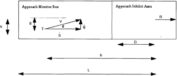
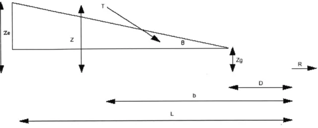
An RCB contains two segments, Approach Inhibit Box (AIB) and Approach Monitor Box
AMB, it is eligible for MSAW approach alerts only, and it is exempt from General Terrain alerts. After eligibility is determined, a glideslope (imaginary approach heading plane) is used to check low altitude violations for the current track. If the track's altitude is below the glideslope at the current aircraft's position minus an approach monitor current alert pad, an alert is raised and the track is sent to the Window Processing Section (WPS).
If the track is not currently violating MSA, the software will check for a predicted violation at an adapted look ahead time, usually 15 seconds. If the predicted future point in which the track falls below a MSA while the track is inside the RCB, but in the AIB and not the AMB, an alert will not be raised. If the predicted point is within the AMB, an alert is raised if it is below the glideslope. In that case, the track is sent to WPS for further processing. If no MSA is violated or will be
violated, the track is returned from Runway Processing.
General Terrain Montonng
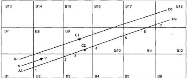
General Terrain Monitoring consists of areas divided into tiles of nautical miles by '/2 nautical miles. Each track is always at a specific tile. Each tile possesses a MSA that is used to detect current and predicted MSAW alerts. The tiles MSA are updated if necessary.
Tracks are placed, based on heading, along a two-segment path, and a MSAW alert is raised if it falls below a MSA anywhere along that path.
Current MSAW Violation Processing
If the track is in violation of MSA in its current tile, or the altitude is less than the MSA of any of the surrounding 8 tiles, all increased by the general terrain current alert pad, a MSAW alert will be raised.
First Segment Processing
A segment is created in this part that extends from the track's current position to the
position it will be at an adapted look ahead time. If the track is at a MSA at the end of the segment, no alert will be raised, and it will be scissored off at that altitude.
The
track's current altitude will then be sent to Mosaic Tile Processing. If the track falls below MSA increased by the general terrain current alert pad along this segment, it will be sent to WPS.Second Segment Processing
Second Segment Processing occurs when the first segment projection was not scissored off or if an alert was not raised along the first segment.
Here, a second segment is created after the first segment using an adapted look ahead time and an adapted ascent angle (about 5 degrees). If between the first segment and the end of the second segment, the track's projection violates any tile's MSA, even if the track ascends at this adapted angle starting at the beginning of this second segment, an alert will be raised and WPS will be invoked.
Mosaic Tile Processing
Mosaic Tile Processing takes two points creating a sort of segment. First, at a crossing from one tile to another, if a track's projected altitude is lower than the tile's altitude or any of its 8 surrounding tiles, an alert is raised. If no violation occurs, it checks the new set of 9 tiles that the track enters, raising an alert if it violates a MSA. Then, if no alerts have been raised, the software re-checks for MSA violations first with the tile it is projected to enter, then with the current tile and its surrounding 8 tiles, then again with the projected tile it is to enter and its surrounding 8 tiles.
Windos Pxssing Section
WPS assigns a design parameter value to any MSAW condition with values according to the following table:
Type of Alert Center Tile Surrounding Tile
No violation 0 0
Predicted 3 1
Current 5 3
The weighted sum of a MSAW alert condition is given by:
S =
9V±+8V
2+7V
+6V4 + V + V6 + V7 + V8 + VV1 is the most recent stored alert value and V9 is the oldest. If S is larger than the threshold value (44), Generate MSAW Alerts will be called with the track's information so that an alert message be created and delivered. WSP will continue delivering the S of the track that raised the alert until that value falls below the threshold value. Once it falls below the threshold value, the track is not in alert and Generate MSAW Alerts will be called off. If S reaches 0, it is taken of the candidate
list
generated by COARSE MSAW FILTER.
Generating MSAWAlerts
This module takes alerts generated by the previous sub functions and formats messages that are sent to the SDDs and to the DRF. An Error Status Information Report is sent to the SMC for display containing information on the message. Additionally, this function will be on regardless of