CLINICAL ARTICLE
Posterior atlanto-axial fixation with polyaxial C1 lateral
mass screws and C2 pars screws
M. Payer&M. Luzi&E. Tessitore
Received: 18 March 2008 / Accepted: 5 August 2008 / Published online: 20 February 2009
# Springer-Verlag 2009 Abstract
Purpose C1-C2 instability or painful osteoarthritis are recognised indications for posterior atlanto-axial fixation. In the traditional trans-articular C1-C2 screw fixation, up to 20% of patients cannot have safe placement of bilateral screws in the event of a medially located vertebral artery and a straight screw trajectory in the sagittal plane. The more recently developed C1-C2 fixation technique with individual C1 lateral mass screws and converging C2 pars screws can be employed in case of a medially located vertebral artery and has comparable biomechanical strength. This is a prospective observational study to investigate the advantages, the safety, and the drawbacks of posterior atlanto-axial fixation with polyaxial C1 lateral mass screws and C2 pars screws.
Methods Twelve consecutive patients with C1-2 instability (n = 11) and painful osteoarthritis (n = 1) underwent a posterior atlanto-axial fixation with polyaxial C1 lateral mass screws and C2 pars screws. The average follow-up was 16 months and all patients reached the 12-month follow-up.
Findings No hardware failure occurred in any of the patients. Correct screw placement and construct stability was found in all 12 patients (100%) at 6 and 12 months after surgery. Mean neck pain on a visual analogue scale (VAS) was 2.1 at 6 months and 2.0 at 12 months. Only
transient complications were observed: one patient pre-sented with progressive intestinal herniation through the iliac crest scar; one suffered from severe pain at the posterior iliac crest for 3 months and three patients complained of annoying pain/dysaesthesia in the C2 dermatome for 3–6 months after surgery.
Conclusion This study confirms that posterior atlanto-axial fixation with polyatlanto-axial C1 lateral mass screws and C2 pars screws is a safe and effective surgical option in the treatment of atlanto-axial instability or painful osteo-arthritis.
Keywords Atlanto-axial . Fusion . Instability . Osteoarthritis
Introduction
The atlanto-axial motion segment accounts for approxi-mately half of the entire normal rotation of the cervical spine, as a result of which external or non-rigid surgical immobilisation is associated with a higher failure rate than in sub-axial segments [4]. The development of rigid screw fixation techniques led to considerably higher C1-C2 fusion rates without the need for rigid external immobilisation in the treatment of acute or chronic C1-2 instability or painful osteoarthritis [7,9,12]. In the direct trans-articular C1-C2 screw fixation technique [12], the straight screw trajectory in the sagittal plane places the vertebral artery at risk and up to 20% of patients cannot have safe placement of bilateral trans-articular screws because of a medially located vertebral artery [1, 11]. More recently, a posterior atlanto-axial fixation technique with separate C1 lateral mass screws and C2 pars screws connected by plates [7] or rods [9] has been introduced. As the C2 pars screws are inserted in a convergent manner, there is a purportedly decreased Acta Neurochir (2009) 151:223–229
DOI 10.1007/s00701-009-0198-4
M. Payer (*)
Neurosurgical Spine Unit, Hirslanden Klinik, Witellikerstrasse 40,
8008 Zürich, Switzerland e-mail: mpayer@hotmail.com M. Payer
:
M. Luzi:
E. TessitoreDepartment of Neurosurgery, University of Geneva, Geneva, Switzerland
risk of inadvertent damage to the vertebral artery and the technique can even be employed in the case of a medially placed vertebral artery [7, 9]. We report our experience using a posterior atlanto-axial fixation with polyaxial C1 lateral mass screws and C2 pars screws in 12 consecutive patients.
Material and methods
Twelve consecutive patients, eight men and four women, with a mean age of 58 years (range 23–78), were admitted to the authors’ institutions (Table 1) with either C1-2 instability (n=11) or painful C1-2 osteoarthritis (n=1). C1-C2 instability was due to pseudo-arthrosis after failed rigid external immobilisation of type II odontoid fractures in three patients (Fig. 1), non-union after failed odontoid screw fixation of type II odontoid fractures in three patients (Fig.2), a complex C1-2 fracture in two patients (oblique odontoid and C2 body fracture with C1-C2 rotatory subluxation) (Fig.3), an unstable Jefferson fracture with a lateral mass overhang of 12 mm in one patient, a C1-2 malformation with hypoplastic C1-2 joints with progressive C1 antero-listhesis in one patient and without an identified cause in one patient (Fig.4).
All patients suffered from severe mechanical upper cervical neck pain. Pre-operative neurological examination was normal in all patients except for one with the C1-2 malformation, who suffered from progressive upper cervi-cal myelopathy with tetra-spasticity and mild tetra-paresis. All patients had pre-operative antero-posterior and lateral cervical spine radiographs as well as thin-sliced cervical spine computed tomography (CT) with sagittal and coronal reconstruction to document the bony fracture, pseudo-arthrosis gap, odontoid screw loosening, bony anomaly or
osteoarthritis. Lateral cervical spine radiographs in flexion and extension demonstrated 8-mm anterior translation of C1 in the one patient without an identified cause of instability and magnetic resonance imaging (MRI) showed no other pathology apart from C1 antero-listhesis. The MRI of the patient with instability from a C1-2 malformation revealed compression of the upper cervical spinal cord with intramedullary hyperintensity on T2-weighted images but no evidence of a Chiari malformation.
Surgical technique
A Mayfield headholder is attached with the patient supine and then turned to the prone position. The head is placed in the military tuck position under lateral fluoroscopic control to achieve some reduction in the case of C1 antero-listhesis. Through a sagittal midline incision from below the inion to the spinous process of C3, the posterior elements of C1 and C2 down to the C2/3 articular line and up to the caudal rim of the foramen magnum are exposed with subperiosteal dissection.
The medial and lateral border of the C1 lateral masses are exposed underneath the posterior arch, which usually requires caudal retraction of the C2 ganglion, especially in case of antero-listhesis of C1. Profuse bleeding from the epidural venous plexus often occurs at this stage and can be effectively controlled by compression with haemostatic sponges and cottonoids.
Under lateral fluoroscopy, bicortical tap drilling through the lateral mass of C1 is accomplished with an electric 2.7-mm drill bit, and self-threading top-loading polyaxial titanium screws with a diameter of 3.5 mm and a length between 30 and 34 mm are inserted (Vertex System, Medtronics, Memphis, Tenn., USA). The drill and screws are directed 10–15° medially and cranially, aiming at the Table 1 Patient overview and clinical results
Patient Age (years) Indication Construct stability
at 6months
Neck pain (VAS) at 6months
Neck pain (VAS) at 12months
1 65 Pseudo-arthrosis type II odontoid fracture Yes 2 2
2 48 Pseudo-arthrosis type II odontoid fracture Yes 5 4
3 75 Non-union type II odontoid fracture Yes 1 1
4 76 C1-2 malformation with instability and myelopathy Yes 4 3
5 78 Non-union type II odontoid fracture Yes 3 5
6 27 Pseudo-arthrosis type II odontoid fracture Yes 2 1
7 23 Complex C1-2 fracture Yes 0 0
8 62 Complex C1-2 fracture Yes 3 2
9 28 Unstable Jefferson fracture Yes 3 4
10 77 Non-union type II odontoid fracture Yes 2 0
11 72 C1-2 osteoarthritis Yes 1 2
anterior tubercle under lateral fluoroscopy. Individual anatomical variations as carefully evaluated on pre-operative CT of every patient were respected. The anterior 18–20 mm of the screw becomes positioned bicortically within the lateral mass and the posterior 12–14 mm remains posterior to the lateral mass to enable later rod anchoring behind the posterior arch of C1 and the C2 ganglion.
The medial border of the C2 isthmus is exposed on both sides. Through separate stab incisions about 6–8 cm lateral from the midline and about 10 cm from the C2 spinous process (which help to limit the length of the wound
incision), the electric drill bit is advanced 14–22 mm into the C2 pars. As suggested by Ebraheim et al. [2], the direction of the drill bit was guided by the medial and superior aspect of the C2 pars, with about 20–25° convergence and 25–30° cranial angle, aiming at the level of the anterior C1 tubercle under lateral fluoroscopy. Self-threading top-loading polyaxial titanium screws with a diameter of 3.5 mm and a length between 14 and 20 mm are inserted. The trajectory and expected length of the C2 screws can be estimated on pre-operative axial CT slices and sagittal CT reconstructions.
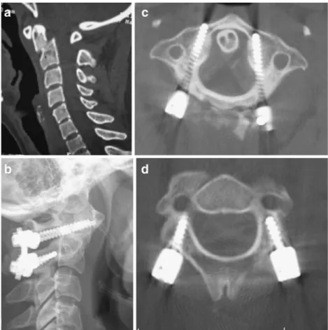
Fig. 1a–d A 27-year-old woman with painful pseudo-arthrosis of a type II odontoid fracture after 3 months of rigid external immobilisation. a Pre-operative sagittal CT reconstruction. b Post-operative lateral cervical spine radiograph. c Post-operative axial CT showing C1 screw placement. d Post-operative axial CT showing C2 screw placement
Fig. 2a, b A 77-year-old man with painful non-union of a type II odontoid fracture 6 months after odontoid screw fixation. a Pre-operative sagittal CT reconstruction. b Post-operative lateral cervical spine radiograph
After placement of all screws, reduction of a mobile antero-listhesis of C1 can now be achieved by pulling the C2 spinous process in a cranial direction with a towel clamp, thus approximating the odontoid process to the anterior arch of C1; rods with a diameter of 3.2 mm are now loaded into the C1 and C2 screw heads on both sides and locked.
The caudal rim of the posterior arch of C1, the cranial edge of the C2 laminae and spinous process are decorti-cated with a high speed drill. A monocortical bone graft from the posterior iliac crest is notched to fit on the decorticated posterior elements of C1 and C2 and attached with a thick non-resorbable nylon suture according to the technique of the Gallie fusion. The wound is closed in a standard fashion over a suction drain.
The patients were mobilised on the first post-operative day in a soft collar, which was worn for 8 weeks. A post-operative CT scan was performed within 3 days to assess the position of the C1 and C2 screws as well as the reduction of the dislocation. Patients were followed prospectively at 6 weeks, 3 months, 12 months and 24 months after surgery, with assessment of neck pain on
a visual analogue scale (VAS), neurological status, and with plain antero-posterior and lateral cervical spine radiographs. CT scans with sagittal and coronal reconstructions were performed 6 months post-surgery to evaluate the fusion. The mean follow-up was 16 months (range: 12–24 months) and all patients reached the 12-month follow-up stage.
Results Surgical results
The mean duration of the procedure was 155 min (range: 90–240). The average estimated blood loss was 480 ml (range: 150–800). The mean length of the C1 lateral mass screws was 32 mm (range: 30–34) and 17 mm (range: 14– 20) for the C2 pars screws (Table2).
Radiological results
On the post-operative CT scan, correct positioning of the C1 lateral mass screws was observed in all 24 placements; Fig. 3a, b A 62-year-old
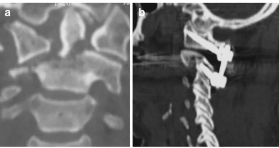
woman with oblique odontoid and C2 body fracture with C1-C2 rotatory subluxation. a Pre-operative coronal CT reconstruction. b Post-operative sagittal CT reconstruction showing C1 and C2 screw placement
Fig. 4a–c A 60-year-old woman with C1-C2 instability of unknown origin. a Pre-operative lateral flexion-extension radiographs showing 8 mm of anterior translation of C1 in flexion. b Post-operative lateral
cervical spine radiograph. c Sagittal CT reconstruction at 6 months post-surgery showing posterior bony fusion between C1 and C2
23 screws had bicortical and one screw had monocortical placement, and no screw perforated the anterior cortex more than 3 mm. Correct positioning of the C2 screws within the C2 pars was found in all 24 placements. Two C2 screws were found to penetrate a maximum of 1 mm into the vertebral artery canal without clinical consequence (Table3).
Post-operative CT at 6 months revealed no screw or rod loosening or breakage in any patient. Plain radiographs at the 12- or 24-month follow-up did not show any change in screw position nor loss of reduction in any patient when compared with the post-operative radiographs. Overall, no hardware failures occurred in any patient. As fusion assessment in the presence of titanium implants is difficult because of metallic artefacts [16], construct stability was defined by the absence of radiolucencies at the screw-bone interface and absence of hardware breakage or displace-ment. According to these criteria, construct stability was achieved in all 24 patients (100%) at the 6-month follow-up and maintained at subsequent follow-ups.
Clinical results
The average length of stay from admission to hospital discharge was 9 days (6–15 days) and the mean post-operative length of hospital stay was 6.3 days (range: 5–9). All 11 neurologically intact patients remained the same after surgery; the patient with cervical myelopathy experienced partial neurological recovery at the 12-month follow-up. Mean neck pain on the VAS was 2.1 (range: 0–
5) at 6 months and 2.0 (range: 0–5) at 12 months and 3/12 patients required irregular intake of non-steroidal anti-inflammatory medication (Table1).
Complications
No vascular or neurological complication was noted. One patient presented with progressive intestinal herniation through the scar over the posterior iliac crest wound; a peritoneal defect was found at revision and repaired with a net 8 months after the C1-2 fixation. Another patient suffered from severe pain at the posterior iliac crest for a period of 3 months. Three patients complained of post-operative occipital pain or annoying dysaesthesia from manipulation of the C2 ganglion, but at the 6-month control these symptoms had completely resolved in all three patients (Table 4).
Discussion
Atlanto-axial instability from trauma, tumour, inflamma-tion, or congenital defect as well as painful osteoarthritis are recognised indications for atlanto-axial fusion [3,9,14,
20]. The posterior approach is by far the most common approach for C1-C2 fixation and dorsal wiring techniques have increasingly been replaced by newer screw fixation techniques [3,9,10,12,14,15,18–20].
Dorsal wiring techniques, such as the Gallie fusion (one wire runs around the posterior arch of C1 and the C2 spinous process with a midline onlay C1-C2 bone graft), the Brooks-Jenkin fusion (one wire runs on each side around the posterior arch of C1 and the lamina of C2 with postero-lateral interlaminar bone graft) and Sonntag’s modified Gallie fusion (one wire runs around the posterior arch of C1 and the C2 spinous process with midline interlaminar bone graft) require intact posterior elements of C1 and C2 and offer limited rotational stability. Therefore, good fusion rates of up to 97% have only been achieved with concomitant post-operative halo fixation for 3 months [14]. While technically more demanding, rigid screw fixation techniques provide significantly higher fusion rates, obviate the need for a post-operative halo immobili-Table 3 Radiological results
C1 screw position on post-operative CT
23 bi-cortical positions 1 mono-cortical position
No medial/lateral or cranial/caudal misplacement
C2 screw position on post-operative CT
22/24 screws completely within bone 2/24 screws with clinically irrelevant penetration into the vertebral artery canal of maximum 1 mm
Construct stability 6 months post-surgery
12/12 patients (=100%) Table 2 Surgical data of atlanto-axial fixations
Average Range
Procedure duration (min) 155 90–240
Blood loss (ml) 480 150–800
C1 screw length (mm) 32 30–34
C2 screw length (mm) 17 14–20
Table 4 Complications encountered
Complication Number of
patients Temporary pain or annoying dysaesthesiae in the C2
dermatome
3 Intestinal herniation through posterior iliac crest scar 1 Pain at the posterior iliac crest 1
sation and can be performed even in the absence of intact posterior elements [14,15].
In 1986, Magerl and Seeman [12] published the technique of direct trans-articular C1-C2 screw fixation, usually combined with one of the dorsal wiring techniques for bony fusion. This technique offers solid biomechanical fixation for flexion/extension and rotation [8, 17], and successful fusion has been reported in 86.9–100% [10,18]. However, as the trajectory of the trans-articular screw is straight in the sagittal plane, up to 20% of patients cannot have safe placement of bilateral screws [1,11]. In a large survey of nearly 2,500 trans-articular screws, inadvertent injury to the vertebral artery has been documented with 2.2% of the screws, resulting in neurological damage in 3.7% of injured vertebral arteries [21].
In 1994, Goel and Laheri published a new plate and screw fixation for atlanto-axial subluxation with separate C1 lateral mass screws and C2 pars screws connected with plates [7]. In 2001, Harms and Melcher [9] described a posterior C1-C2 fixation with polyaxial C1 lateral mass and C2 pars screws, connected with posterior rods. C2 pars screw placement remains technically demanding, but is more widely applicable than trans-articular screws, as the screw trajectory is directed 20–25° medially and thus passes medial of even an enlarged vertebral artery foramen [3, 7, 9, 14, 19, 20]. Additionally, better direct visual control during drilling and insertion of a pars screw has been argued to enhance safety over trans-articular screw placement [7, 9]. So far, no clinically relevant vertebral artery injury from a C2 pars screw has been reported [3,5– 7, 9, 19,20]. However, in the series of Stulik et al. [20], three out of 56 C2 pars screws, i.e. 5.4%, penetrated into the vertebral artery canal without any clinical consequence, attributed to initial lack of experience with a new technique by these authors.“Significant arterial bleeding was encoun-tered” during guide hole drilling in the axis in four out of 160 patients in the series of Goel et al. [5],without post-operative angiographic evaluation and without related symptoms. In the current series, we observed that two out of 24 C2 pars screws had penetrated into the vertebral artery canal with a maximum of 1 mm, without any clinical relevance.
One potential disadvantage of C2 pars screw place-ment over trans-articular C1-2 screw placeplace-ment is the caudal retraction or sectioning of the C2 ganglion for C1 screw placement. In three out of 12 patients, we noted annoying temporary paraesthesiae in the C2 dermatome confined to a maximum of 5 months after surgery. We spared the greater occipital nerve by caudal retraction in all but one patient and the only patient in whom we sectioned the C2 nerve root did not complain of any related symptoms. Goel et al. [5], in their report on 160 patients with separate C1 and C2 screw fixation,
regularly sectioned the C2 gangion sharply to gain wide exposure of the C1 lateral mass and reported no significant clinical symptoms. They attributed this interesting finding to the fact that patients were so satisfied with overall pain reduction and improvement of function that they simply ignored the C2 anaesthesia.
Another potential disadvantage of positioning separate C1 and C2 screws rather than trans-articular screws is the potential misplacement of the C1 screws. The internal carotid artery and the hypoglossal nerve lie within a few millimetres over the anterior aspect of the lateral mass of the atlas and are at risk from excessive anterior penetration during bicortical C1 lateral mass drilling or screw place-ment. However, correct C1 screw position is documented in the series by Harms and Melcher [9], Stulik et al. [20] and Goel et al. [5]. No evaluation of C1 screw positioning is indicated in the reports of Fiore et al. [3] and Stokes et al. [19]. Correct C1 screw placement within the lateral masses was shown in all 24 C1 screws in the current series, with 23 bi-cortical and one mono-cortical position.
Fusion has been documented in all patients treated by posterior atlanto-axial fixation with individual polyaxial C1 lateral mass screws and C2 pars screws [3, 9, 19,
20]. Also in our series, construct stability was documented in all 12 patients at 6 months post-surgery. Biomechani-cally, no significant difference in flexion/extension or rotational stability has been found between the trans-articular technique and the C1 lateral mass-C2 pars screw technique [13,17], which explains the high clinical fusion rates in both methods.
Although the clinical and radiological improvements in the current series are significant, the limited number of patients and the relatively short follow-up are clearly study limitations. On the other hand, a uniform atlanto-axial fixation technique has been consistently applied and prospectively documented and longer follow-ups after achieved fusion is unlikely to change the results obtained in the current series. Larger patient numbers will potentially substantiate further the safety of the described procedure, particularly regarding vertebral artery injuries.
Conclusion
Posterior atlanto-axial fixation with individual polyaxial C1 lateral mass screws and C2 pars screws is a safe and effective surgical option in the treatment of all types of acute or chronic atlanto-axial instability or painful osteoar-thritis. This technique has a very limited risk of vertebral artery injury due to the convergent trajectory of the C2 pars screws, yields a high stability rate, and obviates the need for external rigid immobilisation.
References
1. Abou Madawi A, Solanki G, Casey AT, Crockard HA (1997) Variation of the groove in the axis vertebra for the vertebral artery. Implications for instrumentation. J Bone Joint Surg Br 79:820– 823
2. Ebraheim N, Rollins JR Jr, Xu R, Jackson WT (1996) Anatomic consideration of C2 pedicle screw placement. Spine 21:691–695 3. Fiore A, Haid R, Rodts G, Subach B, Mummaneni P, Riedel C, Birch
B (2002) Atlantal lateral mass screws for posterior spinal reconstruc-tion: technical note and case series. Neurosurg Focus 12(1):E5 4. Fried LC (1973) Atlanto-axial fracture-dislocations. Failure of
posterior C1 to C2 fusion. J Bone Joint Surg Br 55:490–496 5. Goel A, Desai K, Muzumdar D (2002) Atlanto-axial fixation
using plate and screw method: a report of 160 treated patients. Neurosurgery 51(6):1351–1356
6. Goel A, Kulkarni G (2004) Mobile and reducible atlanto-axial dislocation in presence of occipitalised atlas: report on treatment of eight cases by direct lateral mass plate and screw fixation. Spine 29(22):E520–E523
7. Goel A, Laheri V (1994) Plate and screw fixation for atlanto-axial subluxation. Acta Neurochir (Wien) 129(1–2):47–53
8. Grob D, Crisco JJ 3rd, Panjabi MM, Wang P, Dvorak J (1992) Biomechanical evaluation of four different posterior atlanto-axial fixation techniques. Spine 17:480–490
9. Harms J, Melcher RP (2001) Posterior C1-C2 fusion with polyaxial screw and rod Fixation. Spine 26:2467–2471
10. Jeanneret B, Magerl F (1992) Primary posterior fusion C1/2 in odontoid fractures: indications, technique, and results of trans-articular screw fixation. J Spinal Disord 5:464–475
11. Madawi AA, Casey AT, Solanki GA, Tuite G, Veres R, Crockard HA (1997) Radiological and anatomic evaluation of the atlanto-axial trans-articular screw fixation technique. J Neurosurg 86:961–968 12. Magerl F, Seemann PS (1986) Stable posterior fusion of the atlas
and axis by trans-articular screw fixation. In: Kehr P, Weidner A (eds) Cervical spine, vol 1. Springer, New York, pp 322–327 13. Melcher R, Puttlitz C, Kleinstueck F, Lotz J, Harms J, Bradford D
(2002) Biomechanical testing of atlanto-axial fixation techniques. Spine 27:2435–2440
14. Menendez J, Wright N (2007) Techniques of posterior C1-C2 stabilisation. Neurosurgery 60(1 Supp1 1):S103–S111
15. Mummaneni P, Haid R (2005) Atlanto-axial fixation: overview of all techniques. Neurol India 53(4):408–415
16. Narotam PK, Pauley SM, McGinn GJ (2003) Titanium mesh cages for cervical spine stabilisation after corpectomy: a clinical and radiological study. J Neurosurg (2 Suppl) 99:172–180
17. Richter M, Schmidt R, Claes L, Puhl W, Wilke H (2002) Posterior atlanto-axial fixation: Biomechnaical in vitro comparison of six different techniques. Spine 27:1724–1732
18. Stillerman CB, Wilson JA (1993) Atlanto-axial stabilisation with posterior trans-articular screw fixation. Technical description and report of 22 cases. Neurosurgery 32:948–955
19. Stokes JK, Villavicencio AT, Liu PC, Bray RS, Johnson JP (2002) Posterior atlanto-axial stabilisation: New alternative to C1-2 trans-articular screws. Neurosurg Focus 12:1–5
20. Stulik J, Vyskocil T, Sebesta P, Kryl J (2006) Atlanto-axial fixation using the polyaxial screw-rod system. Eur Spine J 16 (4):479–484
21. Wright NM, Lauryssen C (1998) Vertebral artery injury in C1-2 trans-articular screw fixation: Results of a survey of the AANS/ CNS section on disorders of the spine and peripheral nerves. American Association of Neurological Surgeons/Congress of Neurological Surgeons. J Neurosurg 88:634–640
Comment
The authors have reported success in treating 12 patients having craniovertebral instability by lateral mass C1-2 fixation. Over the last 20 years, since we started using this technique of fixation, we have learnt some additional technical tricks which we wish to share. The more difficult technical issue during surgery is the venous bleeding in the lateral gutter over the lateral masses. Relatively quick dissection and compression by gel-foam or Surgicel and cottonoids controls the bleeding. Section of the C2 ganglion provides a panoramic view of the facets and the joint. The entire operation can then be done under direct vision. Wide exposure of the region is necessary to avoid any kind of injury to the vertebral artery and to insert the screws in the optimum direction. Opening of the C1-2 joint, denuding of the articular cartilage and insertion of bone chips within the joint cavity provides remarkable stability to the region by itself. The facet articular surface provides a wide space for bone fusion. If the technique of joint exposure and manipulation is appropriately learnt, the indications for use of lateral mass fixation can be expanded. Direct distraction of the facets of atlas and axis can be used to reduce fixed atlantoaxial dislocation and to treat cases with basilar invagination.
Atul Goel
K.E.M. Hospital and Seth G.S. Medical College Mumbai, India