THE MICROCOMPOSITE CONCEPT IN THE FIELD
OF CERAMIC MATRIX COMPOSITES:
ADVANTAGES AND LIMITS
R. Naslain, J. Lamon, A. Guette, X. Bourrat, F. Langlais, R. Pailler, F. Rebillat, S. Jacques (Laboratoire des Composites Thermostructuraux, UMR-47, CNRS-SEP-University of Bordeaux, 3 Allée de La Boëtie, 33600 Pessac, France)
C. Robin-Brosse, S. Goujard, J.M. Jouin
(Société Européenne de Propulsion, BP 137,33165 Saint Médard-en-Jalles cedex, France)
ABSTRACT: The microcomposite is the elementary cell of a ceramic matrix composite. It consists of one single straight filament coated with a layer of interphase and embedded in the matrix. SiC/SiC microcomposites are prepared by chemical vapor deposition from Nicalon fibers and gaseous precursors. They have two advantages: they can be processed in a very short time and the modelling of their physicochemical and mechanical behavior is relatively straightforward. SiC/SiC microcomposites display a non-linear mechanical behavior under tensile loading conditions similar to that of practical composites. The interfacial parameters have been derived from the tensile stress-strain curves or from push-in/ out data. The matrix crack deflection modes have been directly identified by transmission electron microscopy. Thermal residual stresses have been calculated either analytically or by the finite element method and tentatively measured by X-ray diffraction. The oxidation of SiC/C/SiC microcomposites has been modelled analytically. The oxidation resistance is improved when the PyC-interphase is replaced by (PyC-SiC)n multilayers or by layered materials containing boron (such as B(C) or BN). The limits of the microcomposite concept are discussed.
KEY WORDS: Microcomposite; Nicalon; SiC/SiC; Interphase; Pyrocarbon; BN; Mechanical behavior; Oxidation
1. INTRODUCTION
SiC/SiC composites have been designed for applications at high temperatures in oxidizing atmospheres, e.g. in the aeronautic field. They usually consist of a complex multidimensional fiber architecture which is infiltrated via liquid or gas phase routes, with a precursor of the SiC-matrix. In the so-called CVI-process, this precursor is a gaseous CH3SiCl3 (MTS)/H2 mixture [1]. SiC/SiC composites display a non-brittle mechanical behavior when the bonding between the SiC-based fibers and the SiC-matrix has been properly optimized [2]. The control of the fiber-matrix bonding is usually achieved through the use of a thin interphase, such as a layer of pyrocarbon (PyC) or hex-BN [3]. When exposed to oxidizing atmospheres, SiC/SiC composites experience complex phenomena which may limit their lifetime [4-6].
The study of the processing conditions, of the mechanical behavior and of the effect of the environment for these rather complex materials requires numerous experiments and samples, and can be time consuming. Part of these issues can be treated by cons ide ring model composites, such as the so-called microcomposites. A microcomposite is the unit cell of any ceramic matrix composite (CMC). It consists of one single straight fiber, e.g. a Si-C-O Nicalon fiber (NLM 202 fibers from Nippon Carbon, Japan), coated with a sub-µm layer of the interphase material such as PyC, and finally embedded in the ceramic matrix (here, SiC). SiC/SiC microcomposites are processed by chemical vapor deposition according to a procedure similar to that used for real composites but in a shorter time.
The aim of the present contribution is to show that the basic phenomena controlling the mechanical behavior of CMCs, such as matrix microcracking, crack deflection at the fiber-matrix interfaces, thermal residual stresses and oxidation can be studied on microcomposites, with considerable time saving. Another objective is to show that conversely, the microcomposite approach has also some drawbacks and limits, since it does not take into account the effect of the surrounding fibers.
II. PROCESSING
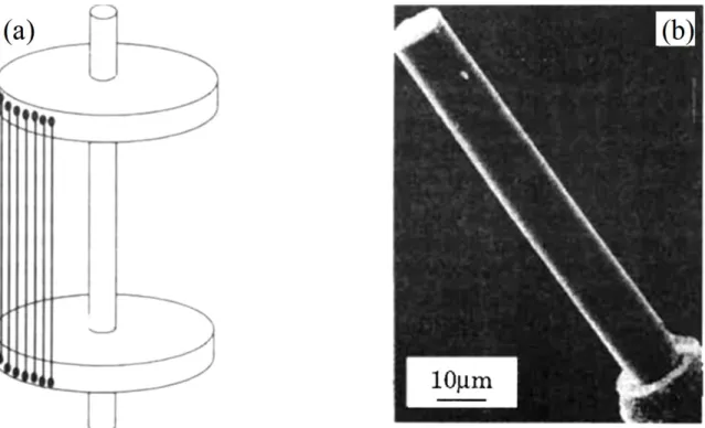
SiC/SiC microcomposites are processed by chemical vapor deposition (CVD) according to a procedure closely related to that used in the CVI-processing of real nD-SiC/SiC composites (with n ≥ 2), the reactants and the furnace being the same [1]. First, in the preparation of a microcomposite, the substrate on which deposition occurs is a straight single filament (≈ 14 µm in diameter, for Nicalon fibers) extracted from a fiber tow. As such a substrate is extremely fragile, it is mounted on a ceramic holder with high temperature cement, to be easily handled (Fig. la). Secondly, during the processing of microcomposites, the single filament substrates are directly in the reactant gas flow (CVD-mode) whereas in that of real composites, deposition occurs in the porosity of a fiber preform (CVI-mode). As a result, the reactant mass transfer to the substrate, the composition of the gas phase near the substrate and hence the deposition rate, are very different. When prepared under optimized conditions, SiC/SiC microcomposites consist of uniaxial concentric shells with a relatively smooth external surface, volume fractions similar to those of real composites and an overall outer diameter of ≈ 20 µm for Vf ≈ 50% (Fig. lb). They can be assimilated to pure 1D-composites with a circular cross-section, in a first approximation.
III. MECHANICAL CHARACTERIZATION
With an overall diameter of ≈ 20 µm, a Nicalon/SiC microcomposite (Vf ≈ 50%) can be tensile tested according to the procedure developed for single filament fibers [7]. For room temperature tensile tests, the microcomposite is first mounted on a window paper (or PVC) frame (gauge length L = 10 or 25 mm) (Fig. 2a). After gripping, the sides of the window frame are cut and the microcomposite is tensile loaded at a constant strain rate (0.1% per min), with a table-model testing machine equipped with a high precision load cell (2N maximum), the grip displacement being measured with a LVDT high resolution transducer (10 mV for 1 µm). An example of tensile curve recorded with unloading-reloading cycles is shown in Fig. 2b for a 1D-Nicalon/BN/SiC microcomposite.
The tensile stress-strain curve of a Nicalon/SiC microcomposite [8-11] exhibits the same general features as those observed for the corresponding 2D-Nicalon/SiC practical composites [12], namely: (i) a linear elastic domain, (ii) a non-linear domain induced by damage phenomena, including matrix micro-cracking and fiber-matrix debonding, and (iii) ultimate failure that occurs with more or less significant fiber pull-out length (Fig. 2b). Furthermore and as shown by various experimental data [11] for a series of Nicalon/BN/SiC microcomposites with BN-interphases deposited in different conditions (Fig. 3) and also by a model of the stress-strain behavior [13], the shape of the tensile curve in the non-linear domain, the number of matrix microcracks, N, the debond length, Id and the fiber pull-out at failure, also depend on the fiber-matrix bonding. However, there are also some noticeable differences with respect to real 2D-composites. In a microcomposite, there is no averaging effect (since it contains only one fiber) as opposed to 2D-real composites where a very large number of fibers contribute to
the overall mechanical behavior. As a result, there is a certain scatter in the experimental data, and fiber interactions are discarded.
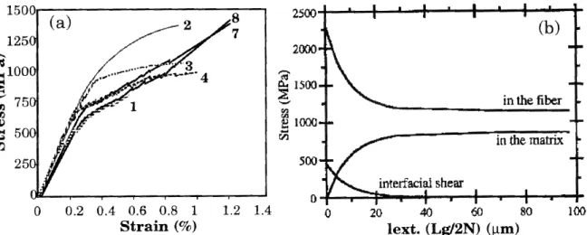
An important advantage of the microcomposite lies in the fact that its mechanical behavior can be modelled relatively easily (it is a pure 1D-composite consisting of uniaxial concentric shells of fiber, interphase and dense SiC-matrix). Thus, the multiple cracking of the matrix and the fiber failure have been modelled in 1D-Nicalon/PyC/SiC microcomposites according to a statistic/probabilistic approach taking into account the fiber matrix bonding (the interfacial parameters being the debond length, Id and interfacial shear stress ) [13]. Weak interfaces (i.e. large Id and small ) limit the matrix microcracking process and decrease the stress at saturation whereas for stronger interfaces (small Id and large ) the matrix microcracking is limited by fiber failure (with a large number of cracks and a higher stress at saturation). The Weibull statistieal parameters pertinent to the SiC CVI matrix (mM = 4.9 and σoM = 2.9 MPa m1.03) are derived from the distribution of the matrix microcracking stresses assessed through a microcomposite tensile test [9]. In a similar manner the fiber-matrix interfacial parameters (which are key parameters for optimizing the processing conditions), namely the interfacial shear stress, , the debond energy, Gic, and the debond length, Id, can be derived from the analysis of the stress-strain curve and unloading-reloading cycles [14]. For the 1D-Nicalon/BN /SiC microcomposite specimens prepared from as-received fibers and whose tensile curves are shown in Fig. 3a, the number of matrix microcracks and the interfacial parameters fall in the following ranges: 9 < N < 55; 3 < < 10 MPa; 0 < Gic < 14 J/m2 and 150 < Id < 600 µm [14]. Finally, the stress fields in the fiber, the interphase and the SiC-matrix, along the fiber axis can be derived from SEM measurements of the in-situ fiber failure stress (mirror radius) and fiber pull-out length. As shown in Fig. 3b for 1D-Nicalon/BN/SiC microcomposites, displays a very high value near the matrix microcrack plane then it decreases exponentially to become very low beyond a 30 µm distance (the mean value derived from integration being ≈ 10 MPa). These results suggest a very short debond [15].
Push-in and even push-out tests can also be performed on microcomposites. However, such tests are difficult to conduct and require a specific specimen preparation [11]. First, the microcomposite is embedded in a stiff enough medium which can be a glass or a ceramic cement. Then, a slab is cut with a diamond saw in a direction perpendicular to the microcomposite axis and polished, the final thickness of the slab being of the order of 200 µm. In a last step, the fiber is pushed-in or pushed-out (depending on the fiber/matrix bonding and slab thickness) with a diamond cone and the interfacial parameters are extracted from the stress-displacement curve according to the models which have been developed for real composites (Fig. 4). Although there is a certain scatter in the data and some difference in the interfacial parameters values (depending on the model used), a relatively good agreement is generally observed between the interfacial parameters extracted from tensile test data and push-in/ out data for the microcomposites, on the one hand, and between those derived from the microcomposites and the real composites, on the other hand [11, 16].
Thermal residual stresses (TRS), which arise during processing from thermal expansion mismatch, can be calculated analytically or according to a finite element approach [9, 17]. Although there is some uncertainty about the thermomechanical properties of pyrocarbon interphase, the calculations suggest that the interphase in SiC/PyC/SiC microcomposite is subject to tensile radial TRS, a feature which is consistent with its function of mechanical fuse (Fig. 5). Preliminary experiments aiming at measuring the TRS in microcomposite by X-ray diffraction have been reported [18].
The characterization of the matrix crack deflection process in microcomposites, by transmission electron microscopy (TEM) is possible. Since the cracks are deflected parallel to the fiber surface, the observation must be conducted on longitudinal thin foils. The preparation of such thin foils is difficult and it requires a specific procedure which has been depicted elsewhere [19]. An example of deflected matrix crack in a Nicalon/C(B)/SiC microcomposite is shown in Fig. 6. In this specimen, the interphase exhibited a composition gradient, the B atomic concentration in the pyrocarbon increasing from 0 (sublayer 1) to 33% (sublayer 5). The matrix crack has been deflected between sublayers 2 and 3 as the result of a change in the texture of the C(B) sublayers [19].
IV. EFFECT OF THE ENVIRONMENT
Below 1100-1200°C (the limit of stability of the Nicalon fiber), the lifetime of SiC/SiC composites in air is controlled by oxidation phenomena [4]. The oxidation of a 1D-SiC/PyC/SiC microcomposite can be modelled analytically (owing to its simple geometry). Two phenomena are in competition: (i) the heterogeneous chemical reactions (the oxidation of the PyC interphase occurs with an evolution of CO/CO2 gaseous species and the formation of an annular pore around the fiber whereas the oxidation of the fiber and the matrix takes place with formation of silica layers on the pore wall) and (ii) the mass transfer of oxygen and CO/CO2 along the pore, by diffusion [20]. At high temperatures (1100-1200°C), silica (whose formation rate is fast) seals the pore entrance and impedes the in-depth gasification of the PyC-interphase and oxygen diffusion (Fig. 7). Under such conditions, the material is self-healing. Conversely, at low temperatures (500-700°C), the oxidation rate of carbon is already fast whereas the formation rate of silica is negligible. As a result, the oxidation of the PyC-interphase proceeds in-depth. Hence, the degradation of the material is more significant at low temperatures. Furthermore, it is enhanced when the SiC-matrix is microcracked (the micro cracks forming new pathways for oxygen diffusion), i.e. when the composite is loaded beyond the limit of linearity.
The effect of an oxidizing atmosphere on the lifetime under load of SiC/SiC composite, can be easily studied through experiments conducted on microcomposites, as shown in Fig. 8a. A constant load is applied to each microcomposite and an electronic device measures the time at failure. The lifetime within the temperature range 500-700°C is improved when the PyC homogeneous interphase is replaced by a (PyC-SiC)n multilayer in which the thickness of the PyC sublayers is lowered [5]. Under such conditions, the in-depth diffusion of oxygen becomes more difficult and the protection by silica more effective. It can also be increased by introducing boron in the interphase (by simple doping or as a layered compound such as BN). The oxidation of boron yields an oxide, B2O3, which remains in condensed state up to at least 1100°C and is known for its healing properties (it fills the microcracks as the y are formed). An example of lifetime curves is shown in Fig. 8b for three kinds of microcomposites with different interphases, which have been exposed in air at a stress higher than the limit of linearity. The lifetimes (corresponding to 50% of the microcomposites broken) are: 24 h for the 1D-Nicalon/PyC/SiC microcomposite (with a PyC thickness of 0.4 µm), 72 h and 120 h for those with interphases of same overall thickness but containing boron (with different concentration gradients for A and A') [6, 10].
CONCLUSION
From the data which have been presented and discussed in sections 2 to 5, the following conclusions can be drawn:
(i)- the microcomposite is the elementary unit cell of a CMC, say a SiC/SiC composite. It contains the three constituents of the composite, i.e. the fiber and the matrix bonded via the interphase as in a real composite. Hence it can be used as a model composite to study the basic phenomena which control the behavior of a CMC from a physico-chemical and mechanical standpoint.
(ii)- the microcomposite has two important advantages versus real composites. First, it can be prepared in a very short time according to the same processing route as that used for real composite (e.g. CVD/CVI). Second, its very simple geometry renders rather straightforward the modelling of the behavior of the material. Hence, the search for correlation between processing, microstructure and properties is much easier.
(iii)- conversely, the use of micro composite has also some limitation. First, the same processing conditions when used to prepare microcomposites and real composites may yield materials with different microstructures, since in the gas phase route the former are processed under CVD-conditions and the latter under CVI-CVD-conditions. As a result, some adjustment of the processing parameters is necessary when moving from the microcomposites to the real composites and vice versa. Second, the microcomposite does not take into account the effect of the surrounding fibers on the elementary cell. For this reason, complementary experiments on minicomposites (infiltrated fiber tows) are useful.
(iv)- taking into account the advantages and limits mentioned above, the microcomposite approach is very appropriate to study the basic phenomena involved in CMCs such as: the fiber-interphase-matrix reactions, the load transfer function, the mechanical fuse function, the relief of TRS by the interphase, the chemical reactions with the atmosphere and its effect on the mechanical behavior. Conversely, in specific domains such as the mechanical properties, the microcomposite is not always representative of real composites and complementary experiments at a larger scale are often necessary.
ACKNOWLEDGEMENTS
This work has been supported by the Ministry of National Education and Research, CNRS and SEP. The authors acknowledge the contribution of different PhD students including J.L. Bobet, L. Filipuzzi, L. Guillaumat, F. Heurtevent and N. Lissart. They are also indebted to F. Lamouroux, J. Forget and C. Dupouy for their assistance in the preparation of the manuscript.
REFERENCES
[1] Naslain R. CVI composites. In "Ceramic Matrix Composites" (R. Warren, ed.), chap. 8, pp. 199-244, Blackie, Glasgow and London, 1992.
[2] Lamicq P J, Bernhart G A, Dauchier M M, Mace J G. SiC/SiC composite ceramics. Ceram. Bull., 65 [2] 336-338 (1986).
[3] Naslain R. Fiber-matrix interphases and interfaces in ceramic matrix composites processed by CVL Composites Interfaces, 1 [3] 253-286 (1993).
[4] Naslain R, Guette A, Lamouroux F, Camus G, Labrugère C, Filpuzzi L, Thébault J. SiC-matrix composites for thermostructural applications: effect of the environment. In Proc. ICCM-I0 (A. Poursartip, K. Street, eds.), Vol. 4, pp. 759-765, Woodhead Publ. Ltd., Abington-Cambridge (UK), 1995.
[5] Heurtevent F. Matériaux multicouches nanoséquencés (PyC/SiC)n : Application en tant qu'interphases dans les composites thermostructuraux. PhD Thesis, Univ. Bordeaux, 29 March 1996.
[6] Jacques S, Guette A, Langlais F, Naslain R, Goujard S. High temperature lifetime in air of SiC/C(B)/SiC microcomposites prepared by LPCVD. Ceram. Trans., 57 (1995) 381-388. [7] Villeneuve J F, Mocaer D, Pailler R, Naslain R, Olry P. Tensile testing at high temperatures of
ex-PCS Si-C-O and ex-PCSZ Si-C-N single filaments, J. Mater. Sci., 28 (1993) 1227-1236. [8] Lamon J, Rechiniac C, Lissart N, Corne P. Determination of interfacial properties in ceramic
matrix composites using microcomposite specimens. In Proc. ECCM 5, Developments in the Science and Technology of Composite Materials, (A.R. Bunsell et al., eds.), pp. 895-900, EACM Publ. Bordeaux, 1992.
[9] Lamon J, Rechiniac C, Roach D H, Jouin J M. Micromechanical and statistical approach to the behavior of CMCs, Ceram. Eng. Sci. Proc., 14 [9-10] 1115-1124 (1993).
[10] Jacques S, Guette A, Langlais F, Naslain R. C(B) materials as interphases in SiC/SiC model microcomposites. J. Mater. Sci., 32 [4] 983-988 (1997)
[11] Rebillat F, Lamon J, Guette A. Interfacial characterization of SiC/BN/SiC composites through tensile tests on microcomposites and on 2D composites and through single fiber push-out tests. Submitted to J. Amer. Ceram. Soc.
[12] Naslain R R. SiC/SiC composites: thermostructural materials for applications in severe environments. This volume.
[13] Lamon J, Guillaumat L. Influence of interfacial characteristics on the nonlinear deformations of ceramic matrix composites. Proceedings of ICCM-10, Whistler, BC, Canada, (A. Poursartip, K. Street eds), Woodhead Publ. Ltd., Vol. IV, pp 649-656, Abington-Cambridge (UK), 1995. [14] Lamon J, Rebillat F and Evans A G. Microcomposite test procedure for evaluating the interface
properties of ceramic matrix composites. J. Amer. Ceram. Soc., 78 [2] 401-405 (1995).
[15] Rebillat F, Crépin-Leblond J, Mougin S, Lamon J. Experimental determination of the stress field in fiber-matrix interphases of microcomposites. Ceram. Trans., 57 (1995) 265-27l.
[16] Kerans R J, Rebillat F. and Lamon J. Fiber-matrix interface properties of single-fiber microcomposites as measured by fiber pushin tests. J. Am. Ceram. Soc. 80 [2] 506–508 (1997). [17] Bobet J L, Lamon J. Thermal residual stresses in ceramic-matrix composites, Part 1-
axisymmetrical model and finite element analysis. Acta Metall. Mater., 43 [6] 2241- 2253 (1995). [18] Bobet J L, Naslain R, Guette A, Ji N, Lebrun J L. Thermal residual stresses in ceramic-matrix composites, Part 2- experimental results for model materials. Acta Metall. Mater., 43 [6] 2255-2268 (1995).
[19] Jacques S, Guette A, Langlais F, Bourrat X. Characterization of SiC/C(B)/SiC microcomposites by transmission electron microscopy. J. Mater. Sci., 32 [11] 2969-2975 (1997)
[20] Filipuzzi L, Naslain R. Oxidation mechanisms and kinetics of 1D-SiC/C/SiC composite materials: 2- Modelling. J. Amer. Ceram. Soc., 77 [2] 467-480 (1994).
FIGURES
Fig. 1. CVD-processing and composition of SiC/SiC microcomposites: (a) single filaments holder, (b) morphology of a SiC/BN/SiC composite failed in tensile loading.
Fig. 3. Tensile tests at room temperature on 1D-Nicalon/BN/SiC microcomposites: (a) for specimens prepared from as-received fibers and BN -interphases deposited under different conditions and (b) stress fields along the fiber-axis (Lg/2N: mean half length of the matrix blocks associated with matrix microcracks) [15].
Fig. 4. Push-out curves for Nicalon/BN/SiC micro- and real-composites according to [11]
Fig. 6. TEM-image of matrix crack deflection (arrows) in a Nicalon/C(B)/SiC microcomposite [19]
Fig. 7. Simulation of the oxidation of the PyC-interphase in a 1D-Nicalon/PyC/SiC microcomposite (PO2 = 100 kPa; T = 1200°C; ePyC = 0.l µm) [20]
Fig. 8. Lifetime of 1D-Nicalon/C(B)/SiC composites in air and under static load: (a) test apparatus and (b) lifetime curves for a 1D-Nicalon/PyC/SiC (sample I) and 1D-Nicalon/C(B)/SiC microcomposites (samples A and A') [10]
barillet en acier inoxydable microcompos ite ciment alumine rés istance chauffante fibre de SiC CVD de 100 µm de diamètre les t (plomb) chronomètre stainless steel heating resistor 100 µm SiC filament load timer
![Fig. 6. TEM-image of matrix crack deflection (arrows) in a Nicalon/C(B)/SiC microcomposite [19]](https://thumb-eu.123doks.com/thumbv2/123doknet/13599871.423814/9.892.285.605.145.524/fig-image-matrix-crack-deflection-arrows-nicalon-microcomposite.webp)
![Fig. 8. Lifetime of 1D-Nicalon/C(B)/SiC composites in air and under static load: (a) test apparatus and (b) lifetime curves for a 1D-Nicalon/PyC/SiC (sample I) and 1D-Nicalon/C(B)/SiC microcomposites (samples A and A') [10]](https://thumb-eu.123doks.com/thumbv2/123doknet/13599871.423814/10.892.265.626.156.969/lifetime-nicalon-composites-apparatus-lifetime-nicalon-nicalon-microcomposites.webp)
