HAL Id: hal-02481756
https://hal.archives-ouvertes.fr/hal-02481756
Submitted on 17 Feb 2020
HAL is a multi-disciplinary open access
archive for the deposit and dissemination of
sci-entific research documents, whether they are
pub-lished or not. The documents may come from
teaching and research institutions in France or
abroad, or from public or private research centers.
L’archive ouverte pluridisciplinaire HAL, est
destinée au dépôt et à la diffusion de documents
scientifiques de niveau recherche, publiés ou non,
émanant des établissements d’enseignement et de
recherche français ou étrangers, des laboratoires
publics ou privés.
Time reversal of photoacoustic waves
Emmanuel Bossy, Khalid Daoudi, Albert-Claude Boccara, Mickaël Tanter,
Jean-François Aubry, Gabriel Montaldo, Mathias Fink
To cite this version:
Emmanuel Bossy, Khalid Daoudi, Albert-Claude Boccara, Mickaël Tanter, Jean-François Aubry, et
al.. Time reversal of photoacoustic waves. Applied Physics Letters, American Institute of Physics,
2006, 89 (18), pp.184108. �10.1063/1.2382732�. �hal-02481756�
Appl. Phys. Lett. 89, 184108 (2006); https://doi.org/10.1063/1.2382732 89, 184108
© 2006 American Institute of Physics.
Time reversal of photoacoustic waves
Cite as: Appl. Phys. Lett. 89, 184108 (2006); https://doi.org/10.1063/1.2382732
Submitted: 13 July 2006 . Accepted: 18 September 2006 . Published Online: 03 November 2006 Emmanuel Bossy, Khalid Daoudi, Albert-Claude Boccara, Mickael Tanter, Jean-François Aubry, Gabriel Montaldo, and Mathias Fink
ARTICLES YOU MAY BE INTERESTED IN Photoacoustic imaging in biomedicine
Review of Scientific Instruments 77, 041101 (2006); https://doi.org/10.1063/1.2195024
Photoacoustic guidance of high intensity focused ultrasound with selective optical contrasts and time-reversal
Applied Physics Letters 94, 054102 (2009); https://doi.org/10.1063/1.3077018 Iterative reconstruction algorithm for optoacoustic imaging
The Journal of the Acoustical Society of America 112, 1536 (2002); https:// doi.org/10.1121/1.1501898
Time reversal of photoacoustic waves
Emmanuel Bossy,a兲Khalid Daoudi, and Albert-Claude Boccara
Laboratoire d’Optique Physique, ESPCI, CNRS UPR 5, 10 Rue Vauquelin, 75231 Paris Cedex 05, France
Mickael Tanter, Jean-François Aubry, Gabriel Montaldo, and Mathias Fink
Laboratoire Ondes et Acoustique, ESPCI, Université Paris VII, CNRS UMR 7587, 10 Rue Vauquelin, 75231 Paris Cedex 05, France
共Received 13 July 2006; accepted 18 September 2006; published online 3 November 2006兲 In this work, the authors use the photoacoustic effect to create a source for ultrasonic time-reversal experiments. Photoacoustic waves were generated by an optically absorbing gel sphere excited by a laser pulse in a highly optically diffusive solution and recorded with an ultrasound array controlled by a time-reversal electronics. The emission of the time-reversed photoacoustic waves allowed the refocusing of the ultrasound towards the optical absorber, in particular, in the presence of a strongly acoustically defocusing medium. The authors illustrate how the technique can be applied to perform acoustical imaging in the presence of a strong acoustical aberration. © 2006 American Institute of
Physics. 关DOI:10.1063/1.2382732兴
For more than a decade, time-reversal techniques have been developed in many different fields of applications in-cluding the detection of defects in solids, underwater acous-tics, room acousacous-tics, and medical imaging and therapy.1,2The essential property that makes time-reversed acoustics pos-sible is that the underlying physical process of wave propa-gation remains unchanged when time is reversed. In a non-dissipative medium, the equations governing the waves guarantee that for every burst of sound that diverges from a source, there is in theory a set of waves that can precisely retrace the path of the sound back to the source. This refer-ence source can be generated by introducing an active source in the desired focal area. In the medical field of lithotripsy, an echo backscattered by a strongly reflecting target共either the kidney stone or gallstone兲 is used as the reference signal for the time-reversed destructing ultrasonic beam.2 In that case, time reversal permits us to correct both for aberrations occurring from medium heterogeneities and for respiratory motion artifacts. However, in many practical situations it is not possible to insert an active source in the medium nor to rely on the presence of a unique strong scatterer. In analogy with adaptive optics in astronomy, it is nevertheless possible to create artificial “ultrasonic stars” in the body. A first ap-proach was recently proposed that consists of inducing a cavitation bubble using an initial focused ultrasound beam in the desired focal area.3 The bubble cavitation generates a spherical wave that can be used as a reference for a second corrected illumination using the time-reversal principle. In this letter, we propose an approach enabling the remote cre-ation of ultrasonic stars in the body without cavitcre-ation. We make use of the photoacoustic effect in order to generate, time reverse, and refocus ultrasound towards an optical contrast.
Optically absorbing regions may indeed act as acoustic sources through the photoacoustic effect described by the following equation: ⌬p − 1 c2 2p t2 = −  cp H t , 共1兲
where p is the acoustic pressure, c the speed of sound,the isobaric thermal expansion coefficient, cp the specific heat,
and H the volumetric density of optical energy per unit time. Physically, photoacoustic waves are therefore pressure waves generated by the thermoelastic expansion that follows the absorption of a light pulse.4,5 This effect is at the origin of recently developed photoacoustic imaging methods, which use passive ultrasonic detection to reconstruct maps of the optical absorption.6–8In biological tissues, which are gener-ally strong opticgener-ally scattering media hindering conventional optical imaging based on ballistic light, these methods pro-vide images of optical absorption with the ultrasonic resolu-tion. In this work, we experimentally perform time reversal of photoacoustic waves generated by an optical absorber em-bedded in a highly optically diffusive medium.
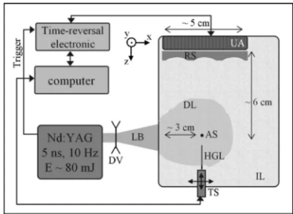
A schematic diagram of the proof-of-principle experi-mental setup is shown in Fig. 1. A frequency-doubled
Q-switched Nd:YAG laser 共=532 nm, Brilliant, Quantel,
France兲 was used to deliver 5 ns light pulses with an energy of approximately 80 mJ per pulse, with a pulse repetition frequency of 10 Hz. A 64-element ultrasound array with a
a兲Electronic mail: [email protected]
FIG. 1. Schematic diagram of the experimental setup. LB: laser beam, DV: divergent lens, DL: diffusive light, AS: absorbing sphere, HGL: hydro-phone, TS: translation stage, IL: Intralipid solution, UA: ultrasound array, and RS: rubber slab.
APPLIED PHYSICS LETTERS 89, 184108共2006兲
central frequency of 1.5 MHz was immersed in a tank and connected to a 64-channel time-reversal electronics共Lecoeur Electronique, Chuelles, France兲. The array dimension is 10 mm along the y axis and has an aperture of approximately 45 mm共interelement pitch of 0.7 mm along the x axis兲. The 64 independent channels allow us to sample the ultrasonic signals on the receive mode 共sampling frequency of 80 MHz兲 and to emit a fully programmable voltage on the transmit mode. The ultrasound acquisition was triggered us-ing the trigger output of the laser Q switch. A 400-m-diameter hydrophone 共HGL-400, Onda Corpora-tion, Sunnyvale, CA兲, mounted on computer-controlled XYZ translation stages, was used to map the ultrasonic field. A standard personal computer was used to control both the electronics and the translation stages and to process the ul-trasonic data. The tank was filled with a 0.4% Intralipid so-lution共obtained by diluting 50 times a stock solution of 20% Intralipid兲 to provide a highly optically scattering medium9 with a reduced scattering coefficient s⬇6 cm−1. Prior to entering the Intralipid solution, the laser beam was expanded to a diameter of the order of 2 cm to minimize parasitic photoacoustic emission created at the surface. A transparent alginate gel sphere, dyed with India ink to obtain an absorp-tion coefficient a⬇10 cm−1, was used as the optical ab-sorber. The diameter of the sphere, approximately 1 mm, was chosen to match the main frequency components of the photoacoustic wave to the frequency bandwidth of the transducer.5 The sphere was fabricated directly on a 100 -m-diameter nylon thread, which was also used to hang and position the sphere in the imaging plane. The sphere was hung into the solution at a location corresponding to a depth of approximately 3 cm relative to the penetration of light共X direction兲. The distance from the sphere to the transducer array was approximately 6 cm共Z direction兲. A Rubber slab with heterogeneous thickness 共varying from approximately 3 to 6 mm兲 was placed against the ultrasound array to pro-vide strong ultrasonic phase aberration. The ultrasound
ve-locity in the slab was 1.1 mms−1 whereas the velocity in the Intralipid solution was approximately 1.5 mms−1.
First, photoacoustic signals generated by the absorbing sphere were measured on the 64-element array, with and without the aberrating slab. Figure 2 shows the two corre-sponding wavefronts. Signals were coherently time averaged 共n=100兲 to improve signal-to-noise ratio. Figure2共b兲clearly shows the wavefront distortion introduced by the aberrating slab. For each case, with and without the aberrating slab, the measured signals were time reversed and reemitted by the array. To assess the quality of the focusing, the hydrophone was linearly scanned along the X direction across the loca-tion of the sphere after the sphere had been removed. Figure
3plots the normalized pressure peak amplitude recorded on the hydrophone and therefore illustrates the quality of the focusing. The focal spot obtained in the presence of the de-focusing rubber slab共solid line兲 turns out to be nearly iden-tical to that obtained without the rubber slab共dashed line兲, which demonstrates that time reversing the photoacoustic wave allows us to refocus with the same quality as that ob-tained in an acoustically homogeneous medium. To illustrate the efficiency of the time-reversal process, Fig. 3also plots the focal spot measured in the presence of the aberrating medium when focusing was performed assuming the me-dium to be acoustically homogeneous共dotted line兲.
Time reversal of photoacoustic waves have several po-tential applications in the context of imaging optically
diffu-FIG. 2. Photoacoustic signals共vertical dimension兲 measured on the 64-element ultrasound array共horizontal dimension兲. 共a兲 Photoacoustic wave-front detected after propagation in the Intralipid solution.共b兲 Photoacoustic wavefront detected in the presence of a strongly defocusing rubber slab pressed against the ultrasound array.
FIG. 3. Maximum signal amplitude detected with a hydrophone, as a func-tion of the hydrophone posifunc-tion across the focal plane. 共—兲 Focal spot generated by time reversing the photoacoustic waves measured in the pres-ence of the defocusing rubber slab.共--兲 Focal spot generated by time revers-ing the photoacoustic waves measured without defocusrevers-ing slab.共¯兲 Focal spot generated by time reversing the photoacoustic signal measured without defocusing slab, but time reversed in the presence of the slab.
FIG. 4. Focal spots measured in the presence of the defocusing slab, gen-erated by time reversing the photoacoustic waves after linear delay laws were added to the signals. The five focal spots correspond to five different delay laws based on propagation in a homogeneous medium, calculated in order to focus at −12, −6, 0, +6, and +12 mm.
sive media. First, a purely optical contrast with no acoustic contrast is not detectable in tissues by conventional ultra-sound, whereas the emitted photoacoustic waves can reveal the presence of the absorber. Furthermore, time reversing the photoacoustic signals and convolving them with long high-intensity sine bursts could allow us to perform high-high-intensity focused ultrasound on targets of optical nature, even if the optical contrast is embedded in an acoustically aberrating medium. Second, a purely optical contrast can be used to focus into an acoustically aberrating medium with the aim of acoustically imaging this medium. We now illustrate this sec-ond example in further detail. A secsec-ond nylon wire was hung about 8 mm away 共along the X direction兲 from the nylon wire supporting the absorbing sphere. The two wires were acoustically equivalent objects, as the acoustic scattering from the optically absorbing gel sphere was negligible com-pared to that from the wires. Our objective was to show that time reversal of photoacoustic waves allows us to acousti-cally image the two wires even when these are located be-hind a highly acoustically aberrating media. The results above show that it is possible to focus toward the optical contrast. However, in order to perform an image, focusing needs to be performed at different locations. While time re-versal only allows us to refocus at the location of the initial source, it is nevertheless possible to steer the beam by delay-ing the time-reversed signals with a linear time-delay law, as would be done for a homogeneous media. In this case, the ultrasonic beam will remain reasonably focused after
steer-ing within a limited region around the original focal point, defined as the isoplanetic region.10,11
Figure4plots the focal spots obtained for different steer-ing angles and shows that under our experimental conditions the isoplanetic region extends over several focal spot widths. In order to image acoustical contrasts located within the isoplanetic region, it is also necessary to beamform the re-ceived signals, as was done to the transmitted signals. As for focusing on the transmit mode, the appropriate time-delay and amplitude laws needed to perform beamforming on the receive mode is not explicitly known. Nevertheless, as the focusing laws are strictly identical for transmit and receive modes, beamforming on the receive mode can be simply obtained by time convolving the received wavefront with the transmitted wavefront and summing the results over all the channels.11 Figure 5 shows two acoustical images obtained with this procedure, with the aberrator pressed against the transducer. Figure5共a兲shows the image obtained in the pres-ence of the slab with standard beamforming, assuming no aberrator. The poor quality of the image further illustrates the strong defocusing effect of the rubber slab. On the other hand, Fig.5共b兲shows the image based on the time-reversed photoacoustic signal, on which the two wires are very clearly distinguished. In this example, the photoacoustic signals were therefore used as a way to learn how to focus in the vicinity of the optical contrast and not to build a photoacous-tic image 共which requires the absence of acoustic aberra-tions兲. The dimension of the image is only limited by the extent of the isoplanetic region. Imaging a larger area would require the existence of several localized optical contrasts under the condition that their associated photoacoustic sig-nals could be discriminated before selectively time reversed. In conclusion, localized optical absorption can act as acoustic sources, which can be used as primary sources for ultrasound time-reversal techniques. As for photoacoustic imaging techniques, this technique is only limited by the amount of light that may reach optical absorbers regardless of the propagation of the light共diffusive or ballistic兲. In the biomedical field, the feasibility of such a technique will de-pend on the existence of well localized optical absorbers or on the ability to produce such absorbers 共using exogenous contrast agents, for instance兲.
1M. Fink, D. Cassereau, A. Derode, C. Prada, P. Roux, M. Tanter, J. L.
Thomas, and F. Wu, Rep. Prog. Phys. 63, 1933共2000兲.
2M. Fink, G. Montaldo, and M. Tanter, Annu. Rev. Biomed. Eng. 5, 465
共2003兲.
3M. Pernot, G. Montaldo, M. Tanter, and M. Fink, Appl. Phys. Lett. 88
共2006兲.
4G. J. Diebold and T. Sun, Acustica 80, 339共1994兲.
5V. G. Andreev, A. A. Karabutov, and A. A. Oraevsky, IEEE Trans.
Ultra-son. Ferroelectr. Freq. Control 50, 1383共2003兲.
6G. Ku, X. Wang, X. Xie, G. Stoica, and L. V. Wang, Appl. Opt. 44, 770
共2005兲.
7M. Xu and L. V. Wang, Med. Phys. 29, 1661共2002兲.
8S. Manohar, A. Kharine, J. C. van Hespen, W. Steenbergen, and T. G.
van Leeuwen, Phys. Med. Biol. 50, 2543共2005兲.
9H. J. Vanstaveren, C. J. M. Moes, J. Vanmarle, S. A. Prahl, and M. J. C.
Vangemert, Appl. Opt. 30, 4507共1991兲.
10M. Tanter, J. L. Thomas, and M. Fink, J. Acoust. Soc. Am. 103, 2403
共1998兲.
11C. Dorme and M. A. Fink, IEEE Trans. Ultrason. Ferroelectr. Freq.
Control 43, 167共1996兲. FIG. 5. B mode ultrasound images of two nylon wires, obtained in the
presence of the defocusing rubber slab pressed against the transducer array. Image共a兲 was obtained without taking into account the presence of the slab. Image共b兲 was obtained by time reversing the photoacoustic waves mea-sured in the presence of the defocusing slab. The optically absorbing sphere was located on the nylon wire located at x = −3 mm.