HAL Id: hal-02481900
https://hal.archives-ouvertes.fr/hal-02481900
Submitted on 17 Feb 2020
HAL is a multi-disciplinary open access
archive for the deposit and dissemination of
sci-entific research documents, whether they are
pub-lished or not. The documents may come from
teaching and research institutions in France or
abroad, or from public or private research centers.
L’archive ouverte pluridisciplinaire HAL, est
destinée au dépôt et à la diffusion de documents
scientifiques de niveau recherche, publiés ou non,
émanant des établissements d’enseignement et de
recherche français ou étrangers, des laboratoires
publics ou privés.
Time reversal kaleidoscope: A smart transducer for
three-dimensional ultrasonic imaging
Gabriel Montaldo, Delphine Palacio, Mickaël Tanter, Mathias Fink
To cite this version:
Gabriel Montaldo, Delphine Palacio, Mickaël Tanter, Mathias Fink. Time reversal kaleidoscope:
A smart transducer for three-dimensional ultrasonic imaging. Applied Physics Letters, American
Institute of Physics, 2004, 84 (19), pp.3879-3881. �10.1063/1.1738186�. �hal-02481900�
Appl. Phys. Lett. 84, 3879 (2004); https://doi.org/10.1063/1.1738186 84, 3879 © 2004 American Institute of Physics.
Time reversal kaleidoscope: A smart
transducer for three-dimensional ultrasonic
imaging
Cite as: Appl. Phys. Lett. 84, 3879 (2004); https://doi.org/10.1063/1.1738186
Submitted: 22 December 2003 . Accepted: 10 March 2004 . Published Online: 29 April 2004 Gabriel Montaldo, Delphine Palacio, Mickael Tanter, and Mathias Fink
ARTICLES YOU MAY BE INTERESTED IN
Acoustic imaging device with one transducer
The Journal of the Acoustical Society of America 131, EL395 (2012); https:// doi.org/10.1121/1.3699533
One-channel time-reversal in chaotic cavities: Experimental results
The Journal of the Acoustical Society of America 105, 618 (1999); https:// doi.org/10.1121/1.426252
In solid localization of finger impacts using acoustic time-reversal process
Time reversal kaleidoscope: A smart transducer for three-dimensional
ultrasonic imaging
Gabriel Montaldo, Delphine Palacio,a) Mickael Tanter, and Mathias Fink Laboratoire Ondes et Acoustique, 10, rue Vauquelin, 75005 Paris, France
共Received 22 December 2003; accepted 10 March 2004; published online 29 April 2004兲
The design of two dimensional共2D兲 arrays for three dimensional 共3D兲 ultrasonic imaging is a major challenge in medical and nondestructive applications. Thousands of transducers are typically needed for beam focusing and steering in 3D volumes. Here, we report a promising approach for producing 3D images with a small number of transducers using the combined concepts of time reversal mirrors and chaotic reverberating cavities. Due to multiple reverberations inside the cavity, a ‘‘kaleidoscopic’’ transducer array is created with thousands of virtual transducers equivalent to 2D matrices. Beyond the scope of 3D medical imaging, this work leads to the concept of ‘‘smart’’ transducer. © 2004 American Institute of Physics. 关DOI: 10.1063/1.1738186兴
A first generation of three-dimensional 共3D兲 ultrasonic scanners have recently appeared in clinical environment, they are able to display the surfaces of some well contrasted interfaces like the face of a baby or the cavities of the heart. These systems combine series of successive 2D images pro-duced by a conventional unidimentional array1moved either by the practician or by a motorized device. A more sophisti-cated approach would consist in designing 2D arrays made of thousands of ultrasonic transducers. However, the problem of connecting such a huge number of elements independently has not been ovecome to date. Therefore, limited subaper-tures of the complete array can be driven simultaneously by the electronics through a complex multiplexing system.1,2
In this letter, we present an approach based on the con-cept of time reversal mirrors. Our goal is to propose a solu-tion that combines the use of time reversal technology with a small number of piezoelectric transducers fastened to a re-verberating solid cavity with one face in contact with the investigated medium. Time reversal focusing has been previ-ously studied in waveguides in the field of ultrasound3and in ocean acoustics.4This technique is based on the reversibility of acoustic propagation5which implies that the time-reversed version of an incident pressure field naturally refocuses in space and time on its source whatever the heterogeneity of the propagation medium. This idea which leads to the con-cept of time reversal pulse recompression in a reverberating medium has been successfully applied in solid waveguides for shock wave lithotripsy.6In such configurations, one face of the waveguide was in contact with a patient body while a small quantity of transducers were glued on the opposite face. Thanks to the multiple reverberations on the waveguide boundaries, the waves emitted by each transducer are multi-ply reflected, creating at each reflection ‘‘virtual’’ transducers that can be observed from the desired focal point. Thus, we create a large virtual array from a limited number of trans-ducers. The result of such an operation is that a small number of transducers is multiplied to create a ‘‘kaleidoscopic’’ transducer array. However, the symmetries implied in
waveguides create periodic kaleidoscopic arrays resulting in grating lobes that limit the interest of this technique to shock wave generation for lithotripsy.
To extend this concept to pulse-echo imaging, sidelobes have to be strongly reduced. The solution we propose is to break waveguide symmetries by introducing reverberating media with chaotic geometries such as chaotic billiards. Pre-liminary work on time reversal in 2D closed cavities was done by Draeger et al. using Bunimovitch billiards.7We ex-tend this work to 3D leaky cavities and we select a Sinai billiard geometry to achieve 3D focusing.
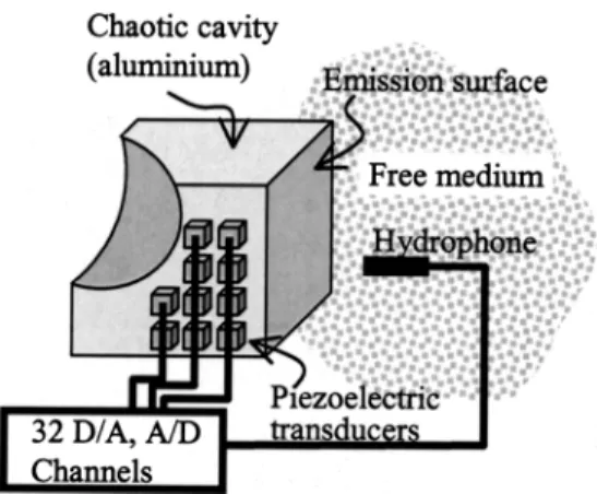
A first 3D Sinai billiard has been designed in duralumi-num (50⫻50⫻50 mm3). Thirty transmit single elements (0.8⫻0.5 mm2 rectangular piezoelectric ceramics, 1.5 MHz central frequency兲 have been glued on one face of the bil-liard. The bottom face has been placed in contact with a fluid medium共see Fig. 1兲. Every transducer has been connected to a fully programmable transmit/receive multichannel elec-tronic system 共32 MHz sampling frequency, 80 Vp p/50⍀).
In order to focus a pulse in any point of the fluid, a time reversal process is implemented. In a first step, an ultrasonic source located at the desired focusing location emits a short
a兲Electronic mail: [email protected]
FIG. 1. Experimental setup. The kaleidoscope is composed by a chaotic cavity in duraluminum and 30 piezoelectric transducers (0.5⫻0.8 mm2)
glued on one face. Each transducer is connected to an independent digital-to-analog and analog-to-digital channel. One surface of the kaleidoscope is in contact with the imaged medium.
APPLIED PHYSICS LETTERS VOLUME 84, NUMBER 19 10 MAY 2004
3879
pulse 共typically, 1 s duration兲. After propagation in the fluid, the resulting wavefront enters the cavity. Due to the strong reverberations inside the cavity, waves are reflected hundreds of times and the impulse responses received by each transducer of the cavity are strongly spread in time 共typically, up to 500 s兲. In a second step, the signals are
time reversed and reemitted by the individual elements. Due to time reversal symmetry, waves refocus at the initial source location both in space and time as if time was playing back-wards. Note, that because of spatial reciprocity, the first step can be achieved in another way. The impulse responses can be successively acquired by emitting a short pulse from each individual transducer and recording the resulting signals with a hydrophone at the desired focus in the fluid.
For each focal point in the fluid, a data set of 30 impulse responses can be acquired and stored in memories. An ex-ample of such ‘‘coda’’ waveforms is shown in Fig. 2共a兲 for a desired focal spot located at 40 mm of depth. It corresponds to nearly 1.5 m reverberant propagation in duraluminum equivalent to nearly 300 reflections on the boundaries. Figure 2共b兲. presents the signal received at the focus after time re-versal and reemission of the 30 coded waveforms. We note a very good temporal recompression of the signal, however, temporal sidelobes remain with a ⫺38 dB level. The hydro-phone can also be used to scan the time reversed wavefield around the focus. Figure 3共a兲 shows the spatial directivity pattern of the maximal pressure field in a plane orthogonal to the beam axis. The ⫺6 dB width is equal to 1.5 mm corre-sponding to a total transmit aperture of 33⫻33 mm2. Spatial sidelobes are also seen in Fig. 3共a兲. and reach a ⫺30 dB level.
This focusing quality in the transmit mode is good and could provide 3D echographic images with a good contrast if we were also able to apply the same focusing concept in the receive mode. In the transmit focusing mode all the coda energy sent from the solid are recompressed in a high ampli-tude pulse by the time reversal process however, the receive focusing mode is not very efficient. Indeed, the signals
com-FIG. 2.共a兲 Signal registered by a transducer of the kaleidoscope after send-ing an impulsion of 2s from a hydrophone. Due to the multiple reflections on cavity faces, the response is very long共up to 500s兲. 共b兲 time-reversal recompression 共2 s兲 received by the hydrophone, the sidelobes have a ⫺38 dB level; 共c兲 first harmonic pulse on the hydrophone; the sidelobes have⫺60 dB.
FIG. 3.共a兲 Spatial quality of the focusing in a plane orthogonal to the beam axis using the fundamental frequency the sidelobes level of the fundamental pulse is⫺30 dB; 共b兲 same than 共a兲 but using the first harmonic the level of the first harmonic pulse is ⫺50 dB; 共c兲 focus on three different points 共pitch 10 mm兲: similar spatial pattern for the fundamental pulse and the first harmonic pulse;共d兲 3D images of a phantom object obtained with the kaleidoscope using 30 emitters and only one omnidirectionnal receiver.
ing back from a target are weak and almost totally reflected at the front face of the chaotic cavity giving rise to very small signals on the transducers. Another drawback comes from the fact that these echoes are superimposed to the re-maining reverberations of the incident wave.
In this letter, we present an elegant solution to this prob-lem by exploiting the nonlinear propagation of the focused beam in the fluid. As the time reversed pulse reaches a very intense amplitude around the focus, nonlinear effects appear in the fluid which give rise to strong harmonic generation. As the harmonic sources depend on the square of the incident pressure field amplitude,8 the directivity pattern of the first harmonic should be cleaned of spurous signals. Figures 2共c兲 and 3共b兲 show, respectively, the first harmonic pulse received at the focus and its spatial directivity pattern. These data are obtained by filtering the first harmonic from the fundamental component using an analogic highpass filter. In Fig. 2共c兲, the temporal sidelobe level has been strongly reduced up to ⫺60 dB while the spatial pattern in Fig. 3共b兲. exhibits a ⫺50 dB sidelobe level.
The ability of this system to focus in a large 3D volume is illustrated in Fig. 3共c兲. The spatial directivity patterns along an axis orthogonal to the beam axis are presented for both fundamental and harmonics while emitting three differ-ent sets of signals adapted to three differdiffer-ent locations. Con-trast improvement with harmonic filtering is maintained on the whole field of interest.
In order to perform an harmonic image of the investi-gated medium we first need to calibrate our time reversal kaleidoscope in a reference homogeneous medium 共water兲 by recording the data sets of emission signals corresponding to a complete 3D volume of focal spots. The technique is then used to focus sequentially on each spot in the region of interest共for medical applications, in the patient body兲. As the biological tissues have nearly the same impedance as water, the kaleidoscope does not see any change and performs the same focusing as in water. The backscattered echoes are re-corded by one or several reception transducers stuck on the front face of the kaleidoscope and centered in the harmonic
frequency. Figure 3共d兲 shows a 3D image of the surface of a gelatin phantom in shape of ‘‘T’’ obtained with the 30 trans-mit transducers kaleidoscope using a single omnidirectionnal receiving element.
The time we need to build an image is limited by the reverberation time in the cavity. To focus a pulse in a point the acoustical signal reverberates nearly 500 s, then, to build a complete image in a grid of 40 by 40 points we need 0.8 s. This is very slow for a real-time visualization. A simple solution to increase the frame rate is to overlap the emissions of different points. For example, if s1(t) is the code to focus in point 1, s2(t) to focus in point 2 and so on, we can send a signal s1(t)⫹s2(t⫹⌬)⫹s3(t⫹2⌬), then, we obtain a se-quence of pulses separated by a time⌬ that focus in points 1, 2, and 3. Using a separation time of 150s the total time of the same image is 0.24 s.
This concept of smart transducers can be extended by using more transducers in the receive mode and a prototype combining 64 transmit and 64 receive elements is currently under construction. Contrary to 2D matrices technology, the system complexity is transferred from connectivity to the more suitable concept of emissions coda stored in memories. This technique has a strong potential for pulse echo medical imaging as well as for 3D shear source generation in soft tissues activated by the ultrasonic radiation force. The poten-tial of such ‘‘smart’’ transducers is also envisioned for ultra-sonic therapy.
1T. R. Nelson and D. H. Pretorius, Ultrasound Med. Biol. 24, 1243共1998兲. 2E. D. Light, R. E. Davidsen, J. O. Fiering, T. A. Hruschka, and S. W.
Smith, Ultrason. Imaging 20, 235共1998兲.
3P. Roux, B. Roman, and M. Fink, Appl. Phys. Lett. 70, 1811共1997兲. 4W. A. Kuperman, W. S. Hodgkiss, H. C. Song, T. Akal, C. Ferla, and D. R.
Jackson, J. Acoust. Soc. Am. 103, 25共1998兲.
5M. Fink, Phys. Today 50, 34共1997兲.
6G. Montaldo, P. Roux, A. Derode, C. Negreira, and M. Fink, Appl. Phys.
Lett. 80, 897共2002兲.
7C. Draeger and M. Fink, Phys. Rev. Lett. 79, 407共1997兲.
8M. F. Hamilton and D. T. Blackstock, Nonlinear Acoustics共Academic,
New York, 1998兲.
3881 Appl. Phys. Lett., Vol. 84, No. 19, 10 May 2004 Montaldo et al.