= ==
=
!Jill
by
J. Antonio Rodri ez
-Sublitted in partial fullfill.ment of the requirerients for the degree
of
BACHELOR OF SCIENCE in CIVIL ENGINEERING at the
Massachusetts Institute of Technology June 1959
,, /
.
.
Signature of Author:
Signature redacted
~.
.
ez
vil Engineering
Signature of Supervisor:
Signature of the Head of the Department:
__
,
.
<
Signature redacted
) I ,, I" V " " '- ""V Prof. Eug:ne Mirabelli 1 / / l • , •Signature redacted
/ John B. Wilbur '1440 Beacon St •
Brookline 46, .Massachusetts May, 1959
Mr.
Secretary of th FacultyMassachusetts Institute of Technology
CUlbridge 49. Massachusetts
Dear Sir:
Sutmitted herewith is a thesis, ntitl d "COMPARATIVE
STUDY OF STRUCTURAL
A.LUMillUM A!IDSTEEL",
in partial!ullfillaent of the requir nts for the degree of Bachelor
of Science frCD the Massachusetts Institute of T chnology.
Respectfully yours,
-Signature redacted
-
rr~ -
..
C??'ae=
=
{ / ., • Anf;onio hodr ezTw author wishos to expesos his gratitud. to Professor Eugene Nirabelli, of the Civil Eugineering Department at the
assaaustts Institute of Technology, for his generous help and encouragmeat in the work ooiectsd with this study.
He wishes also to thank, for their cooperative aid, the
staffs of the AI I Im Cempany of AMerica, aM United States
Steel Corporation. Specially Mr. Cook of Alcoa, and Mr. Oraywork
compare eeenemially has arisen.
The object of this thesis is to owipare the oast of similarly
leaded steel and alimnm uwmbers, designed without any speotfic structure in mind, so as to achieve as much generality as possible.
The results of this study show, that from an ecenomic point
ML MD ... R f ... VL .... VI .... VD .... Aw A 1 ... 00 r ... 00 rxx .... * ryy ... * Ixx .... Iyy ... , PL ... 0.0 Cs ... 0 YO ... c cc. CCC ccc.ececc. . . cecece*c . . ececec*c . .... *.. . ...
madim live moment maxim= impact moment
maid=m dead moment
uniform load reaction
allowable stress maximum live shear maxdmm impact shear maximu dead shear
area of web gross area
unsupported length radius of gyration
radius of gyration about x axis radius of gyration about y axis moment of inertia about x axis momnt of inertia about y axis plate
torsion bending constant
distance from extreme bottom fiber to
Simbol or Abbreviation J ... e... k in2 ...
$
ft. req~d ... O.K. d bt
... Axis x-x .... Q W/T torsion constantfactor representing end condition kips inches square inches pounds dollars feet required an
sheer
stress actualshear
stress acceptabletotal aaxiu= m.ment total Maximum shear
depth
width thickness
horisontal axis quantity
Procndus:
Floor systems of varying span and trmsses of two, four, and six panels, have been designed and compared. Each of the ammbers in a steel trass, has been compared separately with the corres. pending member in the aluminum truss.
Loads caused by a two lane highway, with a standard H20S-16 truck loading, have been used throughout; however, for the purposes of this thesis, any other type of loading could have been used.
The design of the members complies with the specifications of the American Institute of Steel Construction, and the Specifi-cations for Structures of Aluminum Alloy 6061-T6 of the ASCE Proceedings, paper No.970. The AISC Handook (1957) and the
ALCOA Structural Handbook (1958), have been used.
In the design of the members, special care was taken to arrive at the most economical section for each metal, without much atten-tion being paid to the economies brought about by the use, in a
truss, of as many similar members as possible. Due to their variable nature, I have not included fabrication costs.
All members have been designed as welded members. In addition
after welded, in order to regain the strength lest in the welding
process.
The sope of this thesis is to design similarly loaded
ala-mium and steel aembers ad to opare their est. flor systins
of varying span and umners of 3 different trusses haVe been mpared.
The results of this study shew, that frm an 0e4go.ia point
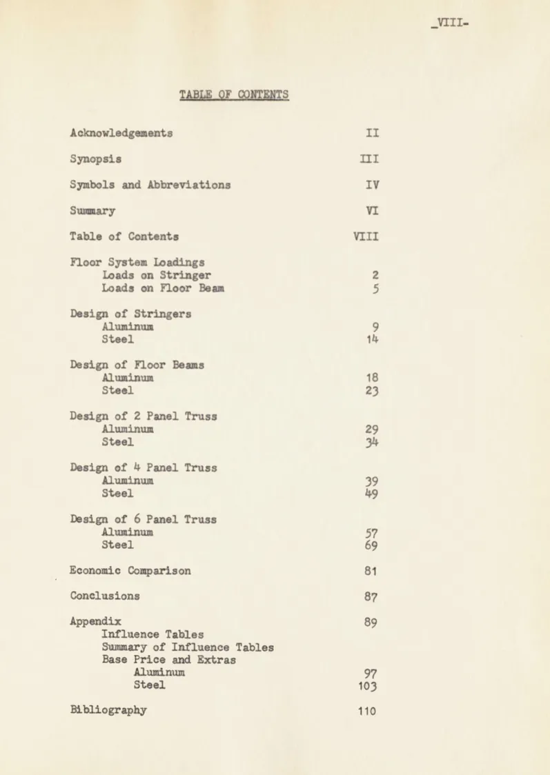
TABLE OF gNMETS
Acknowledgments II
Synopsis III
Symbols and Abbreviations IV
Suawry VI
Table of Contents VIII
Flor Systen loadings
Loads on Stringer 2
Loads anFloor Bean
S
Design of Stringers
AlumInum 9
Steel 14
Design of Floor Beas
Aluminum 18
Steel 23
Design of 2 Panel Truss
Aluminum 29
Steel 34
Design of 4 Panel Truss
Aluminum 39
Steel 49
Design of 6 Panel Truss
Aluminum 57 Steel 69 Econamio Comparison 81 Conclusions 87 Appendix 89 Influence Tables
Summary of Influence Tables Base Price and Extras
Aluminum 97
Steel 103
40* .'6 _ _1.1
As4Mr'g a:
H20-S16 Track Loading.
Thickness of Concrete Slab u 10"
Stringers 0 7 ft. Center to Center.
Leads on Stringers (20 ft. Span)
Maxim= Irinzer LoAdng: (Wheel load on support)
R w 16 (1 + 3/7 + 1/7) a 25.2 k
rincerc L n: (Wheel load not on support)
R = P x K = P
jjg_'
= 20.45 5.5
(b = Spaoing Between Stringers)
ao-.
2.V
VL - 25.2 + 20.4 x La6 31.3 k 2 VI W(31.3)(0.3)
n 9.4
YD-a a) Slab: ( (?)'
8.75 k b) Stringer: Ear AluWMnu:Assume weight of Auminum Stringer = 34 #/ft.
Then, VD I x2g..- 0.35k
2 x 1,000
Assume weight of Steel Stringer - 62 #/ft.
Then, VD n 62 x-2Lu 0.62 k
2 x 1,000
Waim LU12 bamnl:
.q4 K
X = P x L = 20. = 20 102 k -ft.
Ma
(4 g
2 a 1.70 k - ft.8 8
M a W a 6 2 - 3.1 k - ft.
8 8
THEN . FOR ALMI
ML n 102.0 k - ft. MI =
30.6
k -
ft.
MD w.I
k - ft. MT = 178.0 k - ft. VL = 31.3 k Vi = 9.4 k YD = 2@9 k VT a 49.8 k THEN. FOR STlL 102.0 k - ft. 30.6 k - ft. J.la.2 k - ft. 179.5 k - ft. VL =31.3
k Vi a 9.4 kVD*
A
k
VT = 50.1 kA similar procedure has been used for the longer spans. ML
-MD =
FOR 20 ft. STRIN0GER SPAN p= 16 + 16 (A) + 4 (.) * 22 k (20) (20) Mb 0 u 22 (9 + 15 + 24 + 30) - 34 Ra R& = 50.5 k Dgad Lgoa: Ra a W & 2
Due Slab: R& 1&5 x 42.6 k 2 x 1,000
For AuINNIM:
Due Stringer: Ra 34 x 20 3 + 10 +17 + 24 + 31) - 1.70 k
314
Ne Beam: Assume weight a 100 #/ft.
Ra 1 a -. 1.7 k
2 x 1,000
Due Stringer: Ran 64 x 20 = (3 + 10 + 17 + 24 + 31)- 3.1 k 34
Dae Beam: Assume Weight = 200 #/ft.
Ra = 202 x#L = 3.4 k 2 x 1,000
I
9.I
.
~1 ' It
P = 22 k Therefore, Ra a 4 k ML u 44 x 17 - 22 x 8 - 22 x 2 a 527 k - ft. Mi a 527 x 0.30 = 158 k - ft. DeA Lgad: Dae Slab: (2Q)(125)(2!.)(7) - (201)(25) (17)(J2) a 361 k - ft. 1,000 2 1,000 2lor A" I=u:
Due Stringer: x (2.5 x 17) - 3 x-20 (7 + 14) a 14.7 k - ft. 1,000 100 Due Boamt (12 ( 14.6 k - ft. 8 x 1,000 Duo Stringer: 2t2 (2.5 x 17) - A 0(7 + 1) 26.6 k - ft. 1,000 100 Due Beam: 0(])2 a 29 k - ft. 1,000 THEN, FM ALUMM ML a MI a MD = MT = 527.0 k - ft. 158.0 k - ft. .2390, k - ft.
1,075.3
k - ft. VL = VI = VD = VT W 50.5 k 15.2 k 111.7 kMI a 158.0 k - ft. Vi a 15.2 k
ND w _A4 k - ft. VD = 31: k
MT a 1,101.6 k - ft. VT a 114.8 k
A similar procedure has been used for Floor Beaus carrying the longer stringer spans.
Q"Its A imN,4
YL a 31.3 k
VI = 9.A k
VD
a.
k
VT a 49*8 k
3 rAq'd = A 178 & I 132 in3f 14 - 4,v Chec Shart Va =8.5 k/in2 (1)
V
-
L..
. a 4.13
k/in
hwtv 24
x
.5
ML = ND = XT = 278.0 k83.5
k
J&L.1 k550.0 k
ft. ft. ft. ft.i-x
376
+4.3
(12.25)2]2
a1.926
in4
Su u u 154 in3 0.z o 12.5 0. 1. YL = 38.5 k
VI
-11.5 k VD - k I VT - 68,8 k 8roq*d 12 = 472 in' 14(1) ASCE, AS E Procedintgs (May, 1956) Paper No. 970, p.14. ML-M, = ND- NT-102.00 k
30.60
k
178.00 k - ft. -aft - ft. - ft. ""--lChack Shejkri va n 8.5 k/in2 (2) T UgA a 2.87 k/in2
32 x
.75
XL 0 NJ = MD u r=
600 k - ft. 180 k - ft. .. Ujm k - ft. 1,250 k - ft.Ixx n 2,048 + 2 1ii (16.5)21 a 8.o3 in4
3 n LgE 472in3
.
.
17 0. K. VL a VI.= VD w VT.53.8
k
16.2 k3
mR
k
100.0 kSreq'd = I A.U 2 1,070 in'
v. 5 k/in2 (3)
V 100 = 3.14 k/in
2
(2) ASCE, op. cit., p. 14.
(3) ASCE,
op.
cit.,p.
14.I
69909+2L(16z1 )
(26)2
=
28,509
ik
s - 28.-a 1,075 in3 O.K .
938 k - ft. 282 k - ft. _ k - ft. 2,055 k - ft. VL = 64.0 k VI n 19.2 k VD 0 k VT n 125.0 k
Sreqtd = &.55 X. a 1,760 iW3
14 8 Chogk SharX: a a 3.5 k/in2 (4) VS 15 U 3.4 k/ia2
60x .625
I *x a 11,250 + 2 (iB x 1.375)(30.69)2] Ixx - 57,850 in4 0. K.S
n
.1ji
1,1oin3 0. K.31.375
0. K.120
ft. kPa ML = 1,544 k M 1 = 464 k MD = 1.,3Q4 k MT = 3,312 k - ft. - ft. - ft. - ft. Vt = VD = VT = 77.5 k 23.2 k .2a k 152.9 k Sreq'd = 2,440 in3(4) ASCE, op. cit., p. 14.
ML n
MD =
p*-4 9hek Shma Ta g k/lnZ (5) S-
l
- 3.1 k/iU2 Ixxu 17969 + 2 [(22 x 1.375)(33.69)21Ixx =
86*6,5 inW
X
Y ..
37&2
2 520 O
.
,
34-375
MSIGN 07 STINGES
9D-k10 O TRIGOERS N* n 102.0 k -Mi
= 30.6 k
-ND
U.-jJ k -X? - 179.5 k -ft. ft. ft. ft. VL n 31.3 kVI a
9.
k
VDnL
k
VT = 30.1 kSroqtd
a
19..2x
12 a
107.6
a3
20Znz:
18 W 60 s u 107.8 ia3Oak 1or OaL (
va n 13 k/ijt? (6) 13 k/lm2 0. K.
Jl=zil
XL m 278.0 k - ft. NI a 83.5 k - ft. MD = ?JaQQ k - ft.MT
= 561.5 k - ft.VL
U38.5 k
Vi a 11.5 k VD .aUQ k T 7.0 k Sreq'd w 561.5 x 12 a 337 in2 26 30 W 124 (6) AISC, Lc Handbgk (1957) p. 286. 0. K.S
a
354.6 Sn3
gihok for Shuarsva - 13 k/in2 (7) V
iE
70
13
k/ina
2.x .58X n 600.0 k
-NI
180.0 k -ND u.-AIU k -NT = 1278.0 k -ft. ft. ft. ft. Srsq'd 0 1278 _& I& 766 i3 2036
W
230
3 n
835
iW3
hk
for
mshar
va n 13 k/ia
2Sa
313.1
33.36 x .76513 k/ia&
2-_ft sA
ML = NJ = MD = XT =938.0
282.0 2,180.0 k.k k k -ft. ft. ft. ft.(7) AISC, op. cit., p.286.
0. K.
0. K. VL a VI a VD a VT n53.8
k
16.2 k33al. k
103.1 k 0. K. 0. K. VYL VI. VD VT= 64.0 k 19.2 k -ALQ k 131*2 k--- S4
I= a 6, 61 + 2 C(22 x 0.935)(27.47)21
I= a
37,761
in
4S ua =1,350in3 0. .
28 Chegk rar amar-2
va n 4.85 k/in2 v n 1 '.2 ig 4,.85 k/in2
54 x 0.5
-100 ims AR 195"4 k -ft.
.60 k ft. . k - ft.3.043
k - ft. VI U YDU VT77.5 k
23.2 k
1-07 k 160.7 k Sroqd 3.243 x *2 1,825 n3 20 G-egk f - Sher:V
1.7 k/jU26f x .5
I - 9,157 + 2 [(1 x 25) (31)21IME
n57,457 in4
S a =7d 1,825in3
31.5
0. K. ML XTU 0. K. 0. K.1E3IQN OF flO BEAMS
I~E$IGN 07 ~WOR B&&M FOBZOftaSTRIIQUSPAI XL ND -XT = 527.0 k - ft. 158.0 k - ft* _.3ja k - ft.
1,075.3
k - ft.
TL a VI.= VD = VT = 50.5 k 15.2 k .11.7k 111.97 kUsupported lateral lumgth a 7 ft. a*
As a trial s .. 6 8.4 (a) Therefore, f a 14 k/in2 (9) Srsqfd .5 S -1 0 i92 I= 5,760 + 2 1 u 24,960 in 4 S n Z 955 9"ekfa Shoar:
va a
5.7 k/in
2(10)
St 111. - 3.72 k/in2 48 x .625Ckgok for Aullwable S.aA In FlnM: (ii)
so * 955 n j4 1/3
[
2 x 16 (1)3 + 49 (.625)3] . 14.6 nj B Ii d .7 + J (P)I1 d LO16 x 1)(24.5)21 -w3 0 O.K. op. cit., p. 9. op. cit., p. 14. op. cit,, p. 14. op.cit.,
p.9.
.K. (8) (9) (10) (1) ASCE, ASCE, ASCE, ASCE,F V3.58
50&
i7.55Therefore,
Allowable
roa e ft. saiuo SAN
ML
a934.0
k -
ft.
Xi = 280.0 k -f t. ND = .,023. k - ft.XT n
2,023.3 k
-
to.
Stress = 14 k/in2 (12) YL W YV a VD w VT a 0. t. 88.6 k 27.6 k.211..
k
211 .i kSines unsupported length for all Floor bans is the sae as that previous mue, and sin.. this and the following beans are heavier
than the preceding e, w need not wry about bukling.
Therefore, we wifl use f a 14 k/ia2 (13)
3req'd = .023 1 1,730 i3
'1
Check for Ser
Va - 5.25 k/im2 (14) V = a..i - 4.85 k/in2 58 x .73 (12) (13) (14) I = 12,195 + 2
[(18
x 1.375)(29.69)2j
= 53,000
in4
S a ,mRo = 1,820 in330.375
ASCE, op. cit., p. 9. ASCE, op. cit., p. 9.
FS
60
ft.Mrn
SPAN 1,220 k - ft. 366k - ft ja k - ft. 2,826 k - ft. VL = 116.2 k yI a 34.9 k yD = I4k T 294.7 kSroq'd
&o826 &2,20 In
I49hwk
o
m ha
a 6o2 k/in2 (15) - n a 5.27 k/iR2 0 80 ft. SmiG SPI ML . RD w XT a 1,870 k - ft.560
k - ft*i4afk
Ik - ft.4,074
k - ft.xxx
a 19.115 + 2 ((22 x1.375)3.69)2
I=8 3815 184 S 31J a 2,52 n3 O. K33.'3"
0. K. yL a 175.0 k VI n 52.5 k YD = 3 k VT = 421.2 k 3reqtd = 4.074 1xJ&
3,2690 in 14(15) ASCG, op. cit., p. 14. L
-RD *
fta/ -- 70 * / Y& n 6.7 k/in2 (16) v N jLiaLm. 6.02 k/ia2
70 x I
Fm 129 im. 1TNG APA XL u 2,287 k - ft.XN n 696 k - ft.
XDLa.
k - ft.NT
a 5.392 k - ft. rq*d = LI21
- 4,620in3
14Zrz'
27-Z S72w / va = 6.5 k/in2 (17) VMa
= 6.5 k/iA2 72 I z = 28,583 + 2 1(24 x 1.625)(35.81)2) I= n 128,583 in3
-2 3.510 in
0.
K.
0. K.
Y1 D VT = 219.0 k65.0 k
468.2 k I==
31,104 + 2 E(27 x 2)(37) 271=
=
179,000 in4
S= 1229.& 38,720 1n338
0. K. 0* K.(16) ASCE, op. cit., p. 14. (17) ASCE, op. cit., p. 14.
SIGN OF
rLcx
BEAMS IMLlESION OF FLOOR EA1
FOR 20 ft. STRINGER SPAN
ML n 527.0 k - ft. MI- 18.0 k - ft. MD = 416. k - ft. mT 1,101.6 k - ft. Sroq'd
a
1.lL.i.6 x 12 62: 20 In:t33
WF
200
S a 669.6 in 3 Cheak for V: 14
xda--84 &
33
L153
b x t 15.75 x 1.15 Check for Shar:V- 1-1 6 5.2 k/in2
30.70 x .715
FOR 40 ft. STRINGER SPAN
VL = 50.5 k VI - 15.2 k VD = Ad
j
k VT n 114.8 k In3 0. 1. (18) 0. 1. 0. K. ML w 934 k - ft. MI = 280 k - ft. MD = . k - ft. NT = 2,075 k - ft. sreq'd 2.225 x 12 20 88.6 k VI . 27.6 k VD = j4k VT = 218.6 k 1,240 in3L- -an 2.
n
JAII b xt 22 x873 I= a 8,201 + 2 (21 x 7/8)(27.*4)2I= n
35,900 in
4 S a 3,.Lm9 n 1,285 in3 27.875 243 (19) 0. K. 0. 1.Check for Shear:
V. 218.6 .6.5 k/in2
54 x .625
Intrvediate stiffners are needed if v
L
oxceeds MA (20)Au (hvftv)Z
V
a - 8.6 k/in2Therefore, no stiffners required. FOR 60 ft. STRIUKR SPAN
ML n 1,220 k - ft. MI = 366 k - ft. MD.
1=3&
k - ft. XT * 3,018 k - ft. Sreq'd n 3.91 X 1U 20 141T4
(19) (20) VL u 116.2 k Vi = 34.9 k VD a . k VT n 317.8 k 1,810 in3 Ixx a 14,200 + 2 ((1 x 24)(31)2 Ixx = 58,300 in4 S = * =.30Q 1,850 in3 31.5AISC, op. cit., p. 286.
AISC, op. cit., p. 298.
0. K.
l~xn-w 600 (21) b x it 24 x 1
Check for Shear:
T=
31.81
.
n6.95
k/in21 x .75
0. K.
Intermediate stiffners are neoded if v Y. exceeds f (22)
f
9.Ak/in
2Therfore, no stffners required.
FPO 80 ft. STRfI SPAN
HL * 1,870 k - ft.
MI 560 k - ft.
MD w k - ft. T n 4,317 k - ft.
Sreq'd 4.312 &
J&
-20 VL - 175.0 k VI a 52.5 k VD n
ZZLI
k VT = 449.5 k2,59o
in3
Zw
I=a 27,200 + 2 [(1 x 26)(36.5)2]I= a 96,600 in
1 --- 8 S * = 37 2,610 in3LL&
= (84)(74) a 207 (23) b x t (30(0) (21) AISC, (22) AISC, (23) AISC, op. cit., p. 286. op. cit., p. 298. op. cit., p. 286. 0. K. 0. K.Check for Shear:
0. K. V = 449. n 7.13 k/in2
72 x .875
Intermediate stiffners are needed if v
L
excoeds # mw% (24)Av
(hvltv)Z'
( 4,' 2 9.45 k/in
2
Therefore, no stiffners required. FOR 100 ft. STRINGER SPAN
ML n 2,287 k - ft. MI a 696
k -
ft.ND
= k - ft.HT - 5,437
k -
ft.
Sreq'd = 5.-37 x I& 20 VL n 219.0 k VI m 65.5 k VD = k VT - 572.3 k 3,260 in3 -- Z v/ Check for ft L L4 Q 6 =600 (25) b x t 26 x 1Check for Shear
v - 3 6.92 k/in2 84 x I (24) (25) Ixx w 49,400 + 2 [(1 x IXX a 143,200 in 26)(42.5)21 S n 1tt.20
43
0. K. 0. K.AISC, op. cit., p. 298.
AISC, op. cit., p. 286.
Therefore, no stiffners required.
DESIGN OF 2 PANEL TRUSS
TRU53LADN
Uniforu Load- 6u W #/ft. Cao stratod Leads:
a) Chords: 18,000 #/Lan
b) Diagonals and Vertisals: 26,000 #/Lan
Impact w .ni__ but less than 0.30 Live Lead 125 + L
Load Facter = 1.147
Live:
Uniform 29.4 k
Cone. Chord 20.6 k Cone. Diag. and Vert. 29.8 k Dead Leads:
Slab 85.0 k
Stringer 5.4 k
Floor BeaM
Total 92.3 k
AssuMe weight of truss = 0.20 k/ft.
L. L. stress
D. L. Iap-. I + L Total
Stress Uni. Cono. Total Frac. I+I+D
Bar k k k k k k t4LI 0 0 0 0 0 0 L1L2 0 0 0 0 0 0 U0 U1 -50 -14.7 -10.3 -25.0 0.24 -31.0 -82.5 U1U2 -50 -14.7 -10.3 -25.0 0.24 -31.0 -82.5 L 0U0 -50 -14.7 -14.9 -29.6 0.24 -36.8 -88.5 LjU1 0 0 0 0 0 0 L2U2 -50 -14.7 -14.9 -29.6 0.24 -36.8 -88.5 UOLI 70.7 20.8 21.1 41.9 0.24 52.1 124.1 L1U2 70.7 20.8 21.1 41.9 0.24 52.1 124.1
Erx:
'-a 2.3? 10 A2
14.98
3.9
2.23 Area a 2 x 1.97 + 2.23 a 6.19 in2 1 n (1.9)(2.5) + (2.25)(5.125) 6.19 T a 3*46w L0.96
1.66
2
0.92 2.78 '13.62
6.25
18.60 6.25 Total I a 24.85 0. K. rm.= rxe / 2 DRSIGN OF , AND !I UnDesign Load = 124.1 k (Tension)
Area = (3.01)(2) + 2.3 . 8.52 in2 To (3.)(6.02) + 2.5 (7.125) 8.52 To 54.6 in. A L L2 Ij 6.02 1.06 1.12 6.75 K ~/ Z 10
50.45
10 A 2.30 L
2.69
Ij7.25
18.10118 Total I n68.53
rin = r 2.84 Arsq'd n 15 a 8.26 ia2 13DESIGN OF UU1, -1U2,
4OU.,
AND 2P2 Design Load a 88.5 k (Cqmpr..aion)K/2
j l -2 " 7-4/ A10
2- 263.68 12.60 1.17 PL3.0
4.96
ruin n rn w -4.78" Therefore, 7 k/in2 (27) AreqId = a 12.5 in27
0. 1. 0. 1. Area a 12.60 + 3 n 15.60 T (12.60)(6) + 3(12.1z5) u 7.17' 13.60 L1.37
17.3
24,.60
73.8
Total I a 281.0354.8
0. K.(27) ASCE, op. cit., p. 6.
IT
Unifora Lead 0 6,40.0
f/ft.
Coamemtrated loads:
a) chords: 18,000 #/Lanw
b) Diagonals and Vertioalss 26,000 #/Lane
Impat a 50 but los" thas 0.30 Live Toad
Lead Factor a 1.147
TLve s
Uniform 29.4 k
Con.. Mord 20.6 k
Cono. Diag. and Vert. 29.8 k
Dead:
Slab 83.0 k
String 12.4 k
Floor Bea
.3
k
Total 101.2 k
Assume weight of truss n 0.30 k/ft.
Bar D. L. L LA IMp. Total
Stress Uni. Con. Total Fract. I + L I+L+D
LOL1 0.0 0.0 0.0 0.0 0.0 0.0 LjL2 0.0 0.0 0.0 0.0 0.0 0.0 U0 U1
-56.6
-14.7 '-10.3 -25.0 0.24 -31.0 - 87.6 U1U2 -56.6 -14.7 -10.3 -25.0 0.24 -31.0 - 87.6 LOUQ-56.6
-14.7 -14.9 -29.6 0.24 -36.8 - 93.4 LIU1 0.0 0.0 0.0 0.0 0.0 0.0 L2U2 -56.6 -14.7 -14.9 -29.6 0.24 -36.8 - 93.4 U0L1 80.0 20.8 21.1 41.9 0.24 52.1 132.1 LiU2 80.0 20.8 21.1 41.9 0.24 52.1 132.1at
ANL TRMSZn:t
,- ~,g ~ 4LI}4
~.j '.7 AIs a-
all
10 2 - 24.8 PL ---A3.90
2.25 Area a 2 (1.95) + 2.25 - 6.151n
T* .9 x 2.5 + 2.25 & 51T.13
I. L0.96
1.67 02 0.92 2.78 Total 3.60 6.25 In IT 18.4024.63
r *in a rxz E s 2.0D dIN OF L1. *92.k (C. AeND sLo)
Desigm Load = 93.4 k (Couprossim)
L I. Io 133.8 A 8.94
Area
a 2 x #.47 + 2.75 = 11.69 ia2 * 8.9* 1 1 +.7 1 10.125 11. 63To a 6.37"
L1.37
L2 1.88 Ii 16.8 IT l5o.6 0. 1.Total I=
-ai rxz = .- "
Therefore, fall 10.13 k/in? (28) Areqd n 10l a 9.2 in2
10.13
DNOUN AO F UdLi., AND-LizU2
Design Load a 132.1 k (Tension)
Z Area a 2 x 3.36 + 2.5 n 9.22 in2 S- 6.72 x J + 2.5 x 8.13 9.22 To 5.12"
Ku
!p-5
AxLA x - zE I0 PL A 6.72 2.50 L 1.12 3.00 L2- I1 1.25 8.43 9.00 22.30 Total I = - rxx /9 a 3.220 v 9.22(28) AISC, op. cit., p. 209.
0. K. 0. K. 0. K. IT
73.0
'2.3
9305 0. K.q,/ r7 I-'7
@21
0-n
0K.
If)on
I
Panel Leads as in page 30, mopt for the dead load of the truss which we will assme: Wt. of truss n 0.30 k/ft.
D.
L. L.L. Stress IXp. TotalBar Stress Uni. Cone. Total Fract. I+L+D
LOL1 L1L2 L2L3 L3L4 U1 U2 U2U3 U3U4 Uo U1L1 U2L2 U3L3 U4L4 UOL1 UiL2 0.0 156.5
156.5
0.0-156.5
-208.6
-208.6 -156.5 -156.5 - 52.2 0.0 - 52.2 -156.5 222.0 73.6 0.0 4.0 44.o 0.0 -.440 -58.8 -58.8 -44.o -44.0 7.3 -22.0 0.0 7.3 -22.0 -44.0 62*4 31.2 -10.8 0.0 15.4 15.4 0.0 -15.4 -20.6 -20.6-15.4
-22.47.45
-14.90 0.07.45
-14.90 -22.4 31.6 21.1 -10.6 o .o59.4
59.4
0.0-59.4
.79.4-59.4
-66.4 14.75-36.90
0.014.75
-36.90-66.4
94.052.3
0.175
0.175
0*175 0.1750.175
0.1750.175
0.280 0.216 0. 000 0.280 0.216 0.175 0.175 0.216 0.280 0.0 69.8 69.8 0.0. 69.8
-93.3
-93.3
- 69.8 - 78.0 18.9 -44.9
0.0 18.9 - 44.9 - 78.0 110.5 63.6 - 27.4 0.0 226.3 226.3 0.0 ..226.3 -301.9 -301.9 -226.3 -234.5 - 97.1 0.0 -97.1
-234.5
332.5
137.2 * I I I. I ________ I3 2
-10.8 -10.6 -21.4 0.280 - 27.4
Lf Area n 2 x 1.97 + 2.25 - 6.19 ii2 To a (3.941)(2.5) + (2.25)(5.125) 6.19 Tow3- 6 AAS ;& - : I0 2 L-A 14.98 PL 2.25 L
0.96
1.66
0.92 2.78 Ii3.62
6.25
Total I -rain z rxx 9 2DESIGN OF ulhz. AND L2U3
Design Load = 137 k (Tension)
IT 18.60 24.85 7- 354 10 A Area = 6.02 + 3.13 a 9.15 To = (6.01)(3.5) + 3.13 (7.125) 9.15
To
= 4.7" L Ii IT 6.02 1.23 1.51 2 L 43.4 9.10 52.80rain a rxx 0 = 2.83'
Areq'd = = a 9.12 in2
15
DESIGN OF LjI2, AND L2L3
Design Load = 226.3 k (Tension)
Area = 2 x 5.88 + 3.44 = 15.2 in2 - 94 I0 A yo a 11.76 x 4.5 + 3.44 X 9.16 15.2 To a 5.56' L 121.84 11.76 1.06
3.#4
3.60
I1 1.12 14.2 12.95 44.5 IT 136.0 Total I a rain a rxx n 2.4" Areq'd w 15.05 in2DESIGN OF UoLi, AND L3U4
Design load = 332.5 k (Tension)
0. K.
0. K.
180*5
0. K.
/4 12t
AgLw
&W-2 PL 10359.3
A 20.58 3.00 23.5. Yo 6.78* L 0.785.3453
L2 L 0.61 12.3 28.50 85.3 Total I a IT 371.8457.3
0. K. 0. K. rmina rax n 3.4" Argeqd 04314
13
* 22.2 1*2=SIG OF UjLi, AND U.1L1
Design Load = 97.1 k (Cpression)
IZz
Area a 12.60 + 3 n 13.0 102o a
12.60 x 6 + 3x
1.125 T- 7.17" ALga
4 S L2 I 1.37 17.324.6
73.8
Total I = IT 281.0334.8
/2 /Ar- 74 1 2-10 263.7 A 12.603.00
L1.17
4.96
Aroq'd 2l,1 n 13.9 in2
7
Check for local Buckling (30)
(29) ASCE, op. cit., p. 6.
(30) ASCE, op. cit., pp. 11, 12, 13.
B
j /f /.7/ A 19.92 10 629.5 Area - 2 x 9.96 + 3.25 - 23.17 in2 TO = 19.92 x 7.5 + 3.25 x 15.125 23.17 To = 8.58" L 1.08 L1 1.17 IT 23.2 652.73.25
6.55
42.80 139.0 19,. Total I -rain = rxx 5.88" 1 23.17 Therefore, f a 10.2 k/in2 (31) Areq'd a 1092 = 23 in2 (32) 10.*2Check for Local Buckling
IESIGN OF UjU2, AND U2U3
Design Load = 301.9 k (Compression)
Laz:
F
A 7 Area = 19.92 + 10.31 = 30.23 in2 To = 19.92 x 7.5 + 10.31 x 15.28 30*23 YO = 10.2" op. cit., p. 6. op. cit., pp. 11, 12, 13. 791.7 0. K. 0. K. 0. K. (31) (32) ASCE, ASCE,A4iLx - s 10 A 19.92 2.70 10.31
5.18
rain wrxx
=,
a
1w
/30.23
Therefore, f a 10.2 k/in2 (33) Areq'd = 3Qa a 29.6 in2 10.2Check for Local kuokling (34)
3)
Asci, op. cit., p. 6.)
ASCE, op. cit., pp. 11, 12, 13.26.8 Total I = 1,052.0 2"
629.5
L Ii 145.07.3
IT774.5
277.5
&27.5
0. K. 0. K. 0. K.(3
(3
Panel Loads as In page 35, exsept for the dead load of the truss which we will asam: Wt. of truss a 0.30 k/ft.
D. L.. L. . Stress Imp. Imp. Total
Stress. Uni. Conc. _Total Frac. Stress I+L+D
0.0 170.0 170.0 0.0 -170.0 -226.0 -226.0 -170.0 -170.0 LOL1 LiL2 L2L,
L
3L4 UQUl U1U2U
2U
3U
3t
4 UL2 L3U3 L4U4 U0L1 U1L2 U3L2 U4L3 0.0 44.0 44.0 0.0 -44.0 -58.8 -58 .8 -44.0 -44.0 7.3 -22.0 0.0 7.3 -22.0 -44.0 62.4 31.2 -10.8 31.2 -10.8 62.o4 0.0 15.4 15.4 0.0 -15.4 -20.6 -20.6 -15.4 -22.4 7.4 -14.8 0.0 7.4 -14.8 -22.4 31.6 21.1 -10.6 21.1 -10.6 31.6 0.059.4A
59.4
0.0-59.4
-79.4-79.4
-59.4
-66.4
14.7 -36.9 0.0 14.7-36.9
-66.4 94.0 52.3 -21.4 52.3 -21.4 94.00
175
0
175
0.175
0*1750
*175
0.175 0.175 0.280 0.216 0.280 0.216 0*175 0*175 0.216 0*280 0.216 0.280 0.175 0.0 10.4 10.4 0.0 -10.4 -13.9 -13.9 -10.4 11.6 4.1 8.0 0.0 4.1 8.0 11.6 16.5 11.3- 6.0
11.3 - 6.0 16.5 0.069.8
69.8
0.0- 69.8
-
93.3
-93.3
- 69.8 - 78.0 18.1 -44.9
0.0 18.1- 44.9
- 78.0 110.5 63.6 -27.4
63.6 - 27.4 110*5 0.0 239.8239.8
0.0 -239.8 -319.3 -319.3 -239.8 -248.0 -101.5 0.0 -101.5 -248.0 350.5 143.6 143.6 350.5 - 56.6 0.0 - 56.6 -170.0 240.0 80.0 80.0 240 .0 4 PAU& TRU i p -- - -- - - iDESIGN OF tol1, L9LI, AND
!JUj
Design Lad a 0B7
LxIUa l -IV
I0 2&4 14.8 PL A3.90
2.25 Area - 2 (1.95) + 2.25 - 6.15 In2 To a 9 x 2A + 2.25 x 5.11 6.15 To a-*6 L0.96
1.67 L2 0.92 2.6 Total 113.60
6.25
I ' IT 18.40 24.63 0. K. idia = rxz n 20DESIGN OF V1La, AND U1L
Desigp Lead n 143.6 k (Tensica)
-IS 4 8~1 10
6*.6
A 6.72 Area n 2 x 3.36 + 2.5 a 9.22 za2 Te 62x +2.ix 1259.22
To m 5.12" L 1.12 1.25 Ii8.*43
IT73.0
2 " Azin-' . xi10 A 2.50 L
3.00
9.00 Total I = rain a rxx == 9.22 Areqtd = 20%6 7.18 20 DEINOF L1L, AND L U3 3.22' in2Design Load w 101.5 k (Compression)
1UZt Area a 2 x 4.47 + 2.75 - 11.69 in2 o a 9.94 x 5 + .75 x 10.11 11.69 I0 A
133.8
2.75 L 1.373.76
IF I 1.88 16.8 14.10 38.8 Total I = rtin a rxx 4: = 4.04"0 Therefore, f u 10.13 k/in2 (35) Areq'd = 11.,5 = 10 in2 10.13 DESIGN OF L1L2, AND L2L3Design Load m 239.8 k (Tension)
(35) AISC, op. cit., p. 209.
IT 22.5 22.5
95.5
0. K. 0. K.L
f
I1150.6
189.4 0. K. 0. K.-I
//IfL~-
N Ar.aa 2 x 4.39 + 3.44 12.22 1*2 T w8.78 x
j.5 + 3.4x
9.156
12.22 O 5.8' A 8.78 3.4 L 1.y 3.36 L21.069
11.30 Totalraji
a rz 1 2.0" / 12.22 Areq'd a - 12 1,a2 20Deaia Lod n 350.5 k (Tmsoan)
L
-- -/2 M Area n 2 x 7.32 + 3.
17.64 i 2 To= 11.64 z6 + A x- 12,1.3 17.64To
7.05"
L2 I1 1.10 16. 25.8 76.*4 Total I -2 Li 2 " 10 101.4 Ii 14.838.I
I.= IT 116.2 155.1 0. t. 0. K. 10 287 A 14.643.00
L 1.05 5.08 IT 303. 1 isA379.5
20
DESIGN OF ofl. o UOU40 I. AID UIU4
Design lead a 248 k (Cimpression)
=14
K
30 A 10 Area a 2 x 849 + 3 a 20.58 iN2 a= 17.A x + x 12.13 2-L 17.58 0.89 3.00 5.240.79
27.40 1 IT13.9
35.3
82.3 Teta I u r -in a ra. Therefore, f * 11.55 k/iWAreq'd a . 21.A i*2
11.55
Use PL 12 x 5/16
DESIGN OF 192, AND U2U3
0. K.
(36)
Design Lead a 319.3 k (Compression)
(36) AISC, op. cit., p. 209.
TO a 8.?" II
625.2
19.8 1.203.0
rja" - rxx a F 5.860 Thwrfor., f n 13.74 k/in2 (37) Areq'd a a 23.2 in2 Use PL 12 x 5/16 1.486.o
41.010 124.0 Total I a(37) AISC, op. cit., p. 209.
10 A L IT
653.8
777.8
0. K.
'7 c 7 I '7 ~ ' 7____________________
gnm
of)on
an
in
'In
Panel Loads as in page 30 9 eept for the dead load of the truess
whikh we will assme: Wt. of truss a 0.15 k/ft.
Bar II + L
Stress UDI. Cone. Total Frac. Stress I+LD
______ I ______I J .1 _____ r f a LOL1 0.0 0.0 0.0 0.0 0.0 0.0 0.0 L1L2 246.0 73.5 17.1 90.6 0.137 12.3 102.9 348.9
L2L3
393.0
117.6
27.4
145.0
0.137
19.9
164.9
558.0
L
3L
4393.0
117.6
27.4
145.0
0.137
19.9
164.9
558.0
L4L5 246.0 73.5 17.1 90.6 0.137 12.3 102.9 348.9 L5L6 0.0 0.0 0.0 0.0 0.0 0.0 0.0U
0U1
-246.0
-73.5
-17.1
-
90.6
0.137
-12.3
-102.9
-348.9
UiUz
-393.0
-117.6
-27.4
-145.0
0.137
-19.9
-164.9
-558.0
U2U
3-442.8
-132.0
-30.9
-162.9
0.137
-22.3
-185.2
-628.0
U
3U4
-442.8
-132.0
-30.9
-162.0
0.137
-22.3
-185.2
-628.0
U405 -393.0 -117.6 -27.4 -145.0 0.137 -19.9 -164.9 -558.0U5U6
-246.0
-73.5
-17.1
-90.6
0.137
-12.3
-102.9
-348.9
LoUO -246.0 -73.5
-17.1 -90.6
0.137 -12.3 -102.9 -348.9 5.0 5.1 10.1 0.288 2.9 13.0-147.5
- 49.2 -20.0 - 69.20.158
-10.9 - 80.1 -227.6 L2U2 14.7 9.9 24.6 0.226 5.5 30.1 13.4 - 16.7-19.7
-14.9 -34.6
0.186
-6.4
- 41.0-
57.7 L3U3 0.0 0.0 0.0 0.0 0.0 0.0 0.0L. L. Stress Imp. Imp. Total
Bar -I + L
Stress Uni. Cone. Total Frae. Stress I+L+D
L4U4
1
6U6
L3U3 L1 U L2U1 L3U 2 L3U4 L5U6 -16.7
-147*5
-246.0 0.0 W4.0 208* 1 69.869.8
208.1 348.0 14.7 19.7 5.0 -49.2
- 73.5 0.0 104.069.5
7.0 41.2 . 21.0 41.2 - 21.0 69.5 7.0 104.0 9.9 -14.9 5.1 -"20.0 -17.1 0.0 35.2 28.0 -7.1
21.2 -14.0 21.1 -14.0 28.0 - 7.1 35.2 24.6 - 34.6 10.1 - 69.2 - 90.6 0.0 139.297.5
- 14.1 62.4 35.0 62.4 - 35.0 97.5 - 14.1 139.2 0.226 0.186 0.2880.158
0.137
0.137 0.158 0.288 0.186 0.226 o.186 0.226 0.158 0.288 0.1375.5
-6.4
2.9 -10.9 -12.3 0.0 19.1 15.4 - 4.111.6
- 7.9 11.6 -7.9
15.4 4.1 19.130.1
- 41.0 13.0 - 80.1 -102.9 0.0 158.3 112.9 - 18.2 74.0 - 42.9 74.0 - 42.9 112.9 - 18.2 158.3 A I I a I I 13.4 -57.7
-227.6
-348.9
0.0506.3
321.0143.8
143.8 321.o506.3
Area - 2 x 1.97 + 2.25 - 6.19 in2 Y* a (1.91)(2.s) + (2.25)(s.125) 6.19 4 3,416" AAA x - : I0 14.98 A
3.94
2.25
L0.96
1.66
0.92 2.78 Total I n rAn a rxx=9.
9
IZSIGN OF LU2,a AND L3L4
2'0
Design Load = 143.8 k (Tension)
a "4.25 A 10 Area a 2 x 3.62 + 2.5 = 9.74 in2 Y0 - 7.24 x 4 + 2.5 x 8.13 9.74 To a 5.06" L I1 IT 7.24 1.06 1.12 K 2 %. Ij 3.62 6.25 IT 18.60 24.85 0. 1. 2
L-
67.7
8.1 75.810 A 2.5 L 3.07 Total I = ran = r= u 2.8r Aroqtd * .5a* 9.60
L
t 15 DESION OF L114, AND !1LsDesiga Lead n 318.9 k (Tomsisa)
-I/
-r-M
71-Arsa
m19*92
+
3.31 = 23.23 in2
To-
19.92
x.27A+31ta15O
23.23
To=
8.57"
&AM I
wZI 10 2 &. A L19.92
1.07
I1 1.14 22.8 IT652.3
3.31
6.59
43.50
143.7
Total I = rmin mrzz = 2.4 / 23.23 A *d = na1 23.2 in2 15DESIGN OF L2U1 AD 4IE5
)0"
Design Load = 321 k (Temion)
23.5
".3
0. K. 0. K.796.0
O.K . 0. K. II ITI0 A 1! u 7.14' L
324.16
17.64
1.114
3.9
IT 1.30 22.9 24.80 97.0 Total I = rgin = rm n Aroqtd = M 15 11 2.83' u 21. 4 j&2 ESIJ OF -LzL, AnDesign Load = 558 k (Tension)
Area u 2 x 14.70 + 7.88 u 37.28 in2 TO 29.4 x 7.5 + 7.88 x 15.28 37.28 To * 9.120
K
]./5LJ
/f
A L 29.40 1.62 7.88 6.16 I1 2.62 77.0 38.00 299.5 Total I u rain u r= = l37.28 884.322.al
1,183.8 2.0" PL 0. K. 0. K. I0807.3
0. K.Areq#d 0 = = 37.2 jn2
15
DM M OF Lirt. AND L56
W -. 3
Design Lad * 506.3 k (TensiaM) tZ
Area- 29A +
.88
a 34.28 iD2L. j
Areq'd n u 33.8 I 2
rain a rxy S 2.830
DZSIG OF L1 9 AID TT~
Design Toad n 227.6 k (Campression)
ZMS /E & //71 I0 A Area = 19.92 + 3.25 - 23.17 iu2 To 19.92 x 7. + 1.25 1 5.11 23.17
TO
a
8.58 L L2 19.92 1.083.25
6.55
1.17 23.2 652.742.80
139.0
.139.0
0. K. 0.K.
629.5
11 IT Total I=
791.7
rain = rxx
-
I
u.37"
t a 10.2 k/in2H
Areq'd 1 a 22.30 32
10.2
Cheek for local Bholung (39) DESIGN OF flo1. USU2. VA *. AID161
Design Lead n 34.89 k (Comprssioea)
Area = 29.4 +
5.69
-35.09
. + 5.I6935.09
To a 8.741" AELJ'a 10 2 -PL 807.3 1.2.5.69
6.48
1.004
45.2
852.50
42.00239.00
3a. Total I a 1,091.50 * rx 109141 /35.*09 Theroere, f n 9.4 k/la2 (40) Aroq'd - JL1- 37.1U32
9.14Ckwok for local Bakilg (1)
DFSIGN OF 102, AND UOU5
Design Load = 558 k (Comression)
Designed for an unsuprted length of 20 ft.
ASCE, op. cit., ASCE, op. cit., ASCE, op. cit., ASCE, op. cit.,
p. 6. pp. 11, 12, 13. p. 6. pp. Il, 12, IN. 0. K. 0. K. 0. K. -- ? /7418 A L It IT 0. K. 0.K. 0. K. (38) (39) (40) (41) 29.A x 7 5.6w
-r~s
/
/ 807.3 Area a 29.4 + 14 a 43.4 in2 TO - 29.4 x 7.5 +,14 x 15.5 4314 To a 10.00 A 29.4 14.0 L 2.55.5
L2 11 6.25 184.0 30.20 424.7 Total I a a rxx5.75"
Therefore, f a 12.75 k/in2 (42) Areq'd 12.75 - 43,.5 in2Check for Local Buckling (43)
DESIGN OF U2U3, AND U3U4
Design Load = 628 k (Compression)
Designed for an unsupported length of 20 ft.
LEM: -/1-/L- rI.Z8 Area = 29.4 + 14 + 5.25 = 48.65 in2 To = 29.4 x 7.5 + 14 x 15.5 + 5.25 x 16.1 48.65 To = 10.7"
(42) ASCE, op. cit., p. 6.
(43) ASCE, op. cit., pp. 11, 12, 13.
IT
991.30
1,416.00 0. K. 0. K. 0. K.PL 5.25 5.5 30.2 139.0 152 Total I * 1.368
rZa a
r=
5.7
0. K.
Th*rfor., f n 12.8 k/an2 (44) 0. K.
Aroq'd n A 48.5 In2
Cheek for Lmal Baokling (45) 0. K.
DISIGN OF I AND L-U& L"ada 13.4 k (Tension)
57.7 k (Co.prosliAn) Comprasin Load is Critioa
Digp Load n
37.7
+ 13.4 (.3) n 64.4 k (Compression) *Zng:
Area a 4.49 x 2 + 3.73.
12.73 in2To
8.98 x 5 + 3.75 x 10.19 12.73 -/o 6 -a 54* 6.W'*
10
A L L2 II IT 2 134.75 8.98 1.*3 2.37 21.3 156.05* See ASCE Proceedings, Paper #970, pg. 20, &..
(44) ASCE, op. cit., p. 6.
I0 A
3.75
(46) (47) raina
rxa/
au 4.02" 12.73Therofr., fall a 5.05 k/in; (46)
hroqsd a 5a n 12.75 Iu2
5.05
Mc k for Local hakling (47)
ASCE, op. cit., p. 6.
ASCE, op. cit., pp. 11, 12, 13.
L L2 11
13.3
30.0
Total I a IT 206.0 0. K. 0. K. 0. K.-I'E
Pam]1 Load as in page 35 , eoept for the dea load of tb. trass 1hiek wo will assue: W. of truss a 0.0 k/ft-.
D. L. L. L. Stress IMp. Imp. Total
Bar iTI + L
Stress Uni. *
Con.ITotal
Frac.Stress
I+tMDLOL, L1L2 L2L 3 L3L4 L4L5 L5L6 U0U1 U1 U2 U2U3
U34
U4U5 U5U6 LOU0 L1Uj L2U2 L3U 3 0.0 304.0 485.0 485.0 304.0 0.0 -304.0 .485.0 -.546.0 -.546.0-485.0
-304.0 -.304.0 -182.0 - 20.6 0.0 - 20.6 0.073.5
117.6 117.673.5
0.0 -73.5
-117.6 -'132.0 -132.0 -117.6 -73.5
-73.5
5.0
-.49.2 14.7 - 19.7 0.0 14.7 - 19.7 0.0 17.1 27.4 27.4 17.1 0.0 -17.1 -27.4 '30.9-30.9
-27.4 -17.1 -17.1 5.1 -20.0 9.9 -614.9 0.0 9.9 -14.9 0.0 90.6 145.0 145.0 90.6 0.0-
90.6
-145.0
-162.9 -162.0-145.0
-90.6
- 90.6 10.1 - 69.2 24.6 -34.6
0.0 24.6 34.60
*137
0,1370.137
0.1370.137
0.1370.137
0*137 0.1370*137
0,137
0.288 0.158 0.226 0.186 0.226 0.186 0.0 12.3 19.9 19.9 12.3 0.0 '.12.3 -19.9 .22.3 '.22.3 -19.9 -12.3 -12.3 2.9 -010.9 5.5 -6.4
0.0 5.5 - 6.4 0.0 102.9 164.9 164.9 102.9 0.0 -102.9 -164.9 -185.2 -185.2 '164.9 -102.9 -.102.9 2.9 - 80.1 30.1 - 41.0 0.0 30.1 - 41.0 U' J I I I 0.0 406.9 649.9649.9
406.9
0.0 -.406.9-649.9
00731.2 -'731.2-649.9
-406.9 -.406 .9 -262.19.5
- 61.6 0.09.5
- 61.65.0 5.1 10.1 0.288 2.9 13.0 L5U5 .182.0 - 49.2 - 20.0 - 69.2 0.158 .10.9 80.1 .262.1 6U6 -304.0 - 73.5 - 17.1 90.6 0.137 -12.3 -102.9 -406.9
L
1UO
430.0
104.0
35.2
139.2
0.137
19.1
158.3
588.3
258.0
69.5
28.0
97.5
1.158
15.4
112.9
370.9
L2U2 -7.0
- 7.1 - 14.1 0.288 - 4.1 -18.2
86.0 41.2 21.2 62.4 0.186 11.6 74.0160.0
L
3U-
21.0
-14.0
-35.0
0.226
-
7.9
-
42.9
86.0 41.2 21.2 62.4 0.186 11.6 74.0 160.0 L3U4 - 21.0 14.0 - 35.0 0.226 -7.9
- 42.9L4L
5258.0
69.5
28.0
97.5
1.158
15.4
112.9
370.9
- 7.0 - 7.1 - 14.1 0.288 - 4.1 - 18.2L
5U6
430.0
104.0
35.2
139.2
0.137
19.1
158.3
588.3
DISIGI OF 1oLl. LsL6. AND LIU2 Duliga Lad a 0 3Zn 10 A 2 14.8 3.90 PL 2.25 Areas 2 x 1.95 + 2.253 6.13 1n2 Ye
32.9
X2.5
+2.25
15.11
6.13 10. n3o6'
L0.96
1.67 L20.92
2.78 Total 11 3.60 6.23 1 = IT 24.65zAft
= rxx Z " 2.0MINSI OF LIU2. AND EAUS
Daign Load = 160.0 k (Temasin)
, I| ~~ ~~4
~K8L-a1.
I0 A 6.72 Area u 2 x 3.36 + 2.5 n 9.22 ia2 T n 6.72 1 1 + 2.5 x 8.11 9.22 To a 5.120 L 1.12 1.23 118.43
IT73.0
0. K.A 2.50 L
3."
9.oo Toal I ar-ain
rxx
L
2U11'
3.21'
V
9.22Ar.qed 0 *& 8.o iS2 20
DESIGN 01 L291. AN JM0
Design Lead * 370.9 k (TeaiA)
Area u ?.32 x 2 + 4.13 n 18.77 in2
yo
a
1.64 A 6 .11 x 13.188 18.70? Am a=.&:
10 A L 287.01.88
27.5
314.5
23.00
96.0
96.
Tota I rzin a rx. U/- 1 2.83r Areql*d ma! = 18.3 Inj20
DESIGN OF L1L2, AND L5
Design Load = 406.9 k (Tension)
11 I? 22. 5 a1
95.5
0.
K. 0. K. KAY 2 Li Ii IT 410.3 0. lo0.
K. Io L2 14.64 1 *34 4.13 4.82[1
/2.--. 50 Aroa - 2 x 8.79 + 3 a 20.56 Lz2 T n 17. x 6 + x 12.125 20.58 To a6.890
A 17.58 3.00 L 0.89 5.*U L2 110.79
13.9
27.40 82.3 Total I n ZU zn a / arxz 4.5" Areq*d n 0. 20.3 1n2 20 DSION OF L122. AND Ls4D*sinP Load a 568.3 k (Toa.1un)
mmz: