HAL Id: hal-02926218
https://hal.archives-ouvertes.fr/hal-02926218v2
Submitted on 29 Mar 2021
HAL is a multi-disciplinary open access
archive for the deposit and dissemination of
sci-entific research documents, whether they are
pub-lished or not. The documents may come from
teaching and research institutions in France or
abroad, or from public or private research centers.
L’archive ouverte pluridisciplinaire HAL, est
destinée au dépôt et à la diffusion de documents
scientifiques de niveau recherche, publiés ou non,
émanant des établissements d’enseignement et de
recherche français ou étrangers, des laboratoires
publics ou privés.
Modeling Rocky Scenery using Implicit Blocks
Axel Paris, Adrien Peytavie, Eric Guérin, Jean-Michel Dischler, Eric Galin
To cite this version:
Axel Paris, Adrien Peytavie, Eric Guérin, Jean-Michel Dischler, Eric Galin.
Modeling Rocky
Scenery using Implicit Blocks.
Visual Computer, Springer Verlag, 2020, 36 (10), pp.2251-2261.
�10.1007/s00371-020-01905-6�. �hal-02926218v2�
A. Paris1 · A. Peytavie1 · E. Gu´erin1 · J-M. Dischler2 · E. Galin1
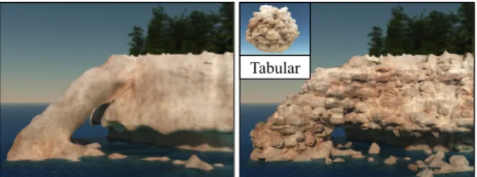
Abstract We present a novel geologically-based me-thod to generate vertical walls of rocky cliffs, crags or promontories. Our method procedurally generates a distribution of fractures in the bedrock to create a set of tiling blocks defined as implicit volumetric primitives. Blocks are in turn implicitly replicated over the verti-cal parts of the terrain and combined together to obtain a consistent volumetric representation of the fractured bedrock patterns using generalized union and blending operators. Our framework provides multiple levels of control: in addition to automatically generated blocks, the geometry of specific ones can be prescribed by the user using implicit primitives or construction trees, the shape of the blocks can be controlled by several param-eters, and the placement rules may adapt according to the underlying geological strata and geometry of the terrain.
Keywords Implicit surfaces · Terrain Synthesis · Procedural Modeling
1 Introduction
Three-dimensional and vertical landforms such as cliffs, steep-walled canyons, crags, promontories, or overhangs are fundamental visual elements of scenic terrains. De-spite the wide application of artificial terrains in the entertainment industry as well as simulation, and ex-tensive research in this area, modeling truly 3D land-forms with a high level of detail such as eroded karst tunnel networks, rocky cliff overhangs and arches with bare rock strata remains an unsolved problem. The vast majority of existing techniques addresses only 212D 1CNRS, Universit´e de Lyon, LIRIS, France
2ICube, Universit´e de Strasbourg, CNRS, France
Tabular
Fig. 1 Given an low resolution input terrain T , our method generates fractured mesoscale blocks featuring small-scale de-tails inside a cubic tile, and replicates them realistically in the scene according to the geology of the different strata.
heightfield terrains which do not allow for an accurate representation of vertical landforms. Even though re-cent advanced techniques for modeling truly 3D ter-rains have been proposed [22, 3, 18], most of them have a limited resolution and only address the generation of large-scale features. Hyper-textures [20] can synthe-size fractal mesoscale and microscale details over the surface of a coarse terrain, however, the self-similar ap-pearance of the resulting bedrock, often corresponding to sandstone, lacks structure. Generating the mesoscale block structures and small-scale patterns of bedrock that appear on bare rocky terrain and the vertical walls of canyons, steep-walled cliffs or promontories, has re-ceived little attention.
The challenge stems from the fact that the geome-try of rocky surfaces results from different physical pro-cesses (including fracturing, percolation, and erosion), depends on the materials involved (such as limestone, dolomite, sandstone or basalt), and shows in a vari-ety of forms (from regular hexagonal prisms to seem-ingly chaotic polyhedral shapes) and scales (from a few decimeters to meters).
In this paper, we propose an amplification method that enhances an otherwise smooth input terrain by
au-tomatically carving geomorphologically consistent vol-umetric details over cliffs and overhangs. Our method consists in reproducing the fractures that exist in the bedrock to generate blocks that will be visible on the vertical walls of cliffs (Figure 1).
More precisely, the main contributions of our work are as follows: 1) we present an original geologically-based fracturing process to generate realistic blocks of rock separated by fractures tiling space; 2) we introduce a novel gradient-based warping operator for adding sur-face details to implicit primitives which allows us to carve small-scale rock patterns from synthetic or real images over blocks; 3) we define a field function node compatible with any hierarchical implicit surface mod-eling framework for replicating the field functions char-acterizing the blocks, therefore implicitly replicating them over a volumetric terrain or a heightfield. Al-together, we provide a unified implicit framework for the representation of mesoscale (≈ 1 m) and small-scale (≈ 1 cm) bedrock details allowing to reproduce complex bedrock patterns and shapes. Moreover, our method provides multiple levels of control, allowing the user to author blocks and tune the placement rules.
2 Related work
Our method relates both to 3D terrain modeling and to hyper-textures or amplification techniques that en-hance an existing coarse terrain representation with smaller-scale details. For a more complete coverage of terrain modeling techniques, the reader is referred to the review in [7].
Voxel representations were first employed for mod-eling volumetric rocky landforms such as cliffs [12] by simulating fracturing between neighboring cells along rock joints. Stability analysis is then applied to remove disconnected cells. Besides memory and computational costs, the method does not scale to large terrains and does not address the distribution of joints crucial for synthesizing patterns observed in nature. Voxels were also used for simulating spheroidal and cavernous ero-sion producing volumetric structures such as hoodoos and goblins [2, 13]. Limiting the range to small features allows to reproduce small-scale details on such specific landforms, but does not lend itself to simulating erosion on large terrains.
Implicit surfaces provide an alternative function-oriented mathematical framework for modeling 3D ter-rains. Peytavie et al. extend the concept of stacked layers, first introduced for erosion simulation, by in-corporating water and air layers and thereby enabling the construction of caves and overhangs [22]. The fi-nal smooth surface is defined as a convolution of these
layers. Although more compact than voxels, material stacks need to be stored explicitly and are limited in terms of precision. Another approach consists in com-bining voxels and feature curves [3] for modeling arches and overhangs. Again the method explicitly stores the voxels of the terrain making it memory demanding. Re-cently, a hierarchical implicit construction tree combin-ing feature primitives [18] was proposed for modelcombin-ing a vast variety of landforms including arches, caves, karsts, sea cliffs, Goblins by simulating erosion processes by an invasion percolation algorithm.
While effective for modeling general landforms, most existing terrain modeling techniques successfully gen-erate smooth large-scale landforms but suffer from a lack of precision and fail at representing mesoscale and small-scale details. While procedural sum of scales-noise functions [6] can in theory compute an infinite amount of details, the self-similar geometries resulting from the fractal process do not capture the characteristic struc-tures and patterns observed on real terrains. In con-trast, our method generates an implicit tiling function combined with small scale gradient-based warping for representing the mesoscale structure and small-scale de-tails conforming to observations in geomorphology.
A common approach often used in the entertain-ment industry consists in decorating a heightfield by distributing 3D meshes taken from an atlas of charac-teristic landforms over the vertical parts on the terrain. A specific technique for generating rock piles was pro-posed in [21]. It consists in creating aperiodic rock tiles to avoid computationally intensive physical simulation for stabilizing rocks. Rock shapes are generated by com-puting the Voronoi cells of a set of seed points using a parametrized anisotropic distance. While this approach can reproduce rock piles found at the bottom of cliffs, it does neither accounts for geological correctness nor follows a joint model, and therefore fails at reproducing certain types of blocks. Ghost Tiles introduced in [11] use a densely populated tile with pre-computed inter-sections to synthesize the multitude of entangled ob-jects fallen to the ground such as rocks, branches or leaves. Those methods do not address the synthesis of geologically consistent fractures and do not create real-istic block structures.
Finally, textures without uv-maps can be used to add details terrains by displacement mapping [28], but only few texturing methods can be applied to introduce real 3D features. Hyper-textures [20, 6] often based on noise [19] allow the synthesis of a theoretically infinite amount of volumetric details. Hyper-textures perturb an initial smooth volumetric model by adding a frac-tal density function or warping space. Although this method generates fractal surfaces with self-similar
fea-tures such as powdery rocks or eroded limestone, it fails at reproducing block structures such as fractured sand-stone or columnar basaltic shapes. Cellular textures [25] can be easily adapted to generalized Voronoi diagrams and synthesize volumetric blocks patterns. Discrete el-ement textures [15] synthesize distributions of objects using a small input examplar, however, there is no guar-antee to obtain geologically correct block structures. Texel mapping enhances the surface of an object with details stored in voxel grids and replicated around the surface of the input object [16]. This method produces 3D features on a thick layer only, requires an explicit parametrization of the surface, but fails at generat-ing geomorphologically coherent mesoscale block struc-tures, which is the focus of our work. An important aspect of our method is that it is compatible with these texturing techniques, which can be invoked to synthe-size small and micro-scale details.
Contrary to previous approaches, our method is ca-pable of reproducing geologically correct blocks enhanced with small-scale details and implicitly places and com-bines them over the original terrain to produce a de-tailed representation featuring the complex patterns ob-served in real landscapes.
3 Overview
Real terrains often feature complex rock formations in areas such as cliffs or caves. These landforms are the re-sult of complex, interconnected physical processes that include glacial erosion, catastrophic rock collapses due to instability, or aeolian erosion. To avoid computation-ally intensive simulations, we propose a procedural ap-proach to create block formations based on classifica-tions used in geomorphology.
Polyhedral Equidimensional Prismatic
Tabular Rhombohedral Columnar Fig. 2 Categories of blocks identified in geomorphology cor-responding to various fracture distributions.
Our work comes from the observation that fractures in bedrock form blocks exhibiting a variety of shapes of different sizes. Archetype structures such as prismatic,
equidimensional or rhombohedral (Figure 2) have been identified in geomorphology [17, 5]. A fracture is a break of continuity in the body of rock whose origin is nat-ural. It most frequently occurs as fracture sets that are defined as a family of parallel, evenly spaced bro-ken fractures that can be identified by analyzing their orientations, spacing, and physical properties. Regular and periodic distributions of fractures result in regu-lar columnar blocks, whereas distributions with three major orthogonal directions result in equidimensional blocks; randomly distributed fractures produce polyhe-dral type. 2D Terrain T Amplified 3D terrain T Tile generation Amplification ~ User control
Set of cubic tiles C featuring blocks
Fig. 3 Overview of the algorithm: during a pre-processing step, we generate cubic tiles containing 3D blocks of distinct types according to different fracture distributions, then given an initial coarse heightfield, strata definition and control re-gions, we automatically generate a 3D implicit model defined as a field function replicating the blocks for creating mesoscale and small-scale details.
Fracturing the entire input terrain T would be com-putationally and memory intensive. Therefore, we pro-pose a procedural tiling method. The goal is to compute cubic tiles containing geologically correct blocks that will be placed over the vertical parts of bare bedrock.
The overall terrain amplification process is com-posed of two steps (Figure 3). We first generate a set of blocks Bi organized into a cubic tile denoted as C using
a procedural fracturing approach based on a geomor-phological classification (Section 4). These blocks Bi
are implicitly defined by scalar functions bi : R3 → R,
which allows to obtain a 3D volumetric representation of the mesoscale patterns and small-scale details using a new gradient-based warping operator.
The second step consists in amplifying a smooth in-put terrain T by replicating blocks over the bare verti-cal parts of the bedrock (Section 5). The input terrain can be any kind of 212D heightfield (resulting from
edit-ing, simulation, procedural generation or synthesized from examples, we refer to [7]), or a 3D terrain model (see Section 2). The new 3D detailed terrain model eT is defined as an implicit surface whose scalar field func-tion ef is a construction tree combining the field function of the initial terrain f and the scalar functions of the blocks bi.
The cubic tile C is virtually tiling R3, and only the blocks Bi that straddle the vertical parts of the
ter-rain are replicated. To avoid explicit instantiation, we propose an original selective field function replication method inspired from [23] that allows to virtually repli-cate the field functions bi of the blocks only over the
vertical parts of the input terrain.
4 Block tile generation
The key process in the formation of blocks is fracturing. In geomorphology, fractures are represented and simu-lated using 3D discs that define the formation of blocks by breaking the continuity of the bedrock.
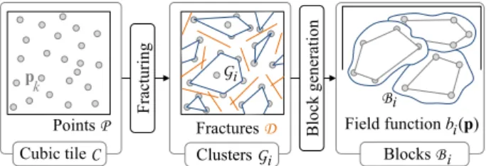
From this observation, we propose a procedural and controllable method to simulate the different types of block formations as found in nature. We address the generation of blocks tiling space. In the following sec-tion, we consider periodic tiling out of clarity, the gener-ation of aperiodic tiling using Wang Cubes [4] or Corner Cubes [14, 21] is a direct technical generalization of this work. Therefore, we address the generation of blocks in a cubic tile C of size s (in our implementation we use a cube with size s ≈ 20 m). The algorithm proceeds in two steps as depicted in Figure 4.
Fr actu rin g Blo ck g en er atio n Clusters G FracturesD i Blocks Bi Cubic tile C Points P k Bi Field function b (p)i Gi p
Fig. 4 Blocks generation pipeline inside a cubic tile C. We first compute a nearest neighbor graph G over a set of sam-ple points P inside the tile. Fracturing discs D remove edges crossing fractures. We extract clusters Gi as the set of
dis-connected sub-graphs, and generate implicit primitives Bifor
each cluster. For the sake of clarity, the method is depicted in 2D and edges of G are not represented.
Fracturing. Starting from an initial set of points P = {pk} sampling the cubic tile, we compute the
geo-metric nearest neighbor graph G over this set. A set of fractures D = {Di} where Diare discs is then generated
using procedural rules. These fractures cut edges from
the graph, thus creating connected sub-graphs called clusters and denoted as Gi that will finally form the
blocks.
Implicit primitive generation. The coarse ge-ometry of the blocks is defined as the convex hull of the point sets for every cluster Gi. For every block, we
define a scalar function bi that computes a signed
dis-tance bound to the surface of the block. Its correspond-ing construction tree combines the planes of the convex hull using a smooth intersection operator. The convex blocks are responsible for the mesoscale details of the bare rock. We finally apply a new gradient-based warp-ing operator for generatwarp-ing the small-scale volumetric details.
4.1 Fracturing
The fracturing process starts by generating a set of sam-ple points pk inside the cube, using a Poisson sphere
distribution. Experiments demonstrated that a regu-lar sampling leads to 3D aliasing with unnatural axis-aligned fractured shapes.
The Poisson radius r influences the size and shape of the blocks. Higher radius values yield tiles with fewer points inside, which in turn leads to blocks with coarser convex shapes and fewer polygonal faces after the frac-turing process. For a cubic tile size of s ≈ 20 m, we generate points with a Poisson radius r ≈ 10 cm which leads to ≈ 14 000 points. After fracturing, each block contains between 80 and 150 sample points (see Ta-ble 1). We then compute the nearest neighbor graph G connecting the set of points P using r as the neighbor-ing distance threshold, i.e. an edge between points pi
and pj exists if kpi− pjk < r.
Fractures Di(ci, ri, ni) are defined as discs in space
characterized by their centers ci, radii ri and normal
orientation ni. Geomorphological types are distinguished
by the way fractures are distributed in the cube, i.e. by the following parameters: number of fractures, average radius size, distribution of disc centers, and relative ori-entations. Without loss of generality, discs centers ciare
randomly generated in the cube using a Poisson sphere sampling with an average radius of ≈ 2 m. Both ri and
ni distributions are tuned according to the block type
(see Figure 5).
The user may control the fracturing process either by tuning the disc distribution parameters, or by plac-ing specific fractures in the cubic tile, or by directly placing several authored blocks in the tile (see Fig-ure 6), and the system will adapt. It is also possible to increase the overall amount of fracture by decreas-ing the Poisson radius of the fracture centers
distribu-tion. Other disc sampling strategies could be used, how-ever we found Poisson sampling practical for obtaining regular-pattern-free distributions with a practical con-trol over the disc centers spacing.
The following paragraphs explain the different frac-ture distributions, as described in [17] and their control parameters.
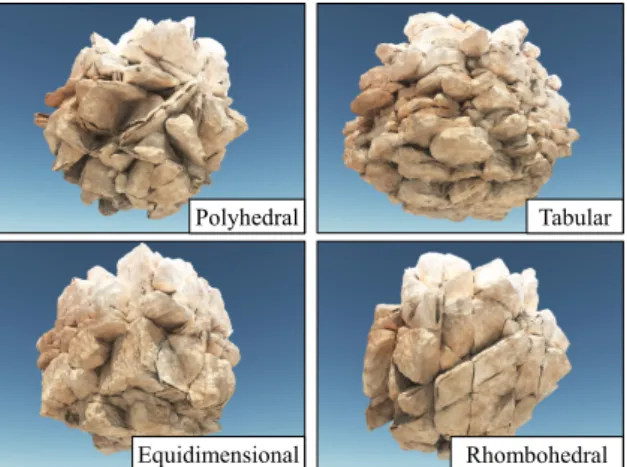
Polyhedral Tabular
Equidimensional Rhombohedral
Fig. 5 Different types of blocks generated with different disc distributions.
Equidimensional block type has three dominant sets of fractures, approximately orthogonal, with occasional irregular fractures, giving almost cubic-shaped blocks. Prismatic blocks are similar in shape but are formed under slightly more irregular fracture distributions. For these types, normals ni are determined using a random
axis-aligned direction. Radii ri are randomly chosen in
an interval given by a user parameter. In our experi-ments, we set the radii to ≈ 5m.
Polyhedral type shows irregular small blocks without explicit arrangement into distinct sets. This type re-quires more fractures due to the completely stochastic essence of the distribution, therefore we set the radius of the fracture centers distribution to ≈ 1 m and create more fractures.
Rhombohedral blocks have three (or more) dominant mutually oblique sets of fractures, giving oblique-shaped blocks. The parameters are the same as for equidimen-sional blocks, but with tilted axis-aligned directions to obtain diagonal orientations.
Tabular block type has one dominant set of parallel fractures orthogonal to a dominant axis direction, for example bedding planes, with other non-persistent frac-tures; thickness of blocks is much lower than length or
width. Discs orthogonal to the dominant axis orthogo-nal have a large radius equal to the size s of the cubic tile C, whereas the other discs parallel to the two or-thogonal axes occur less frequently, and have with small radii ri ≈ s/10.
Columnar type is composed of several (usually more than three) sets of continuous, parallel fractures. The length is much greater than other dimensions.
Type #P #D #B #Pi Time
Equidimensional 14 524 15 125 110 6.9 Rhombohedral 14 589 24 78 161 12.0 Polyhedral 14 532 44 100 140 25.4 Tabular 14 554 30 82 143 16.3 Table 1 Statistics for the generation tiles: number of points #P, number of fracture discs #D, number of blocks #B, av-erage number of points #Piinside a block Bi, and generation
time (in seconds).
The next step consists in removing edges cut by a disc Di and then create clusters Gi of connected nodes
pk. This is performed by using a greedy algorithm:
starting from a random point, aggregation propagates through the graph until no more points can be con-nected. Formally, an edge pjpk is kept if it does not
intersect any fracture:
∀ Di ∈ D, Di∩ pjpk= ∅
Finally, we check that all the points in a given clus-ter are visible to each other, i.e. that fractures do not cut an edge connecting any pair of points in the cluster. This guarantees that clusters should not spread around fracture discs, which would create blocks that do re-spect the constraints.
Rhombohedral Tabular
Fig. 6 Example of user-control during the fracturing step: the user authored specific tabular blocks (left), and rhombo-hedral blocks (right) inside an equidimensional block tile.
The complexity of the fracturing step depends on the number of fractures #D: a highly fractured cube will require more intersection tests between edges of
the graph and the discs. Table 1 reports some statistics for the different types illustrated in Figure 5.
4.2 Implicit block generation
Recall that we aim at generating an amplified terrain model eT as an implicit surface. Implicit surfaces allow us to create a unified volumetric representation for both the base terrain and the mesoscale and small-scale de-tails of the bedrock. We create the scalar field bi from
the previously computed clusters Gi as a construction
tree defined as the smooth-intersection of half-spaces forming a base convex shape, and then deformed using a gradient-based warping operator (Figure 7).
Smooth intersection Set of planes H
Warping
Prismatic Tabular
Fig. 7 Simplified hierarchical representation of blocks Bi:
the base convex shape is defined as the smooth intersection of a set of plane primitives H, and procedurally warped.
We first compute the convex hull of each cluster and extract a corresponding polygonal mesh Mi. We
compute the planes Hk = (ok, uk) associated to every
polygon of Mi such that their normal uk should be
oriented towards the exterior of Mi. The
correspond-ing scalar function of the convex base ci is defined as
the smooth intersection of the half-spaces functions hk
associated to planes Hk. Every half-space is defined by
the signed distance to the plane hk(p) = (p − ok) · uk.
The final implicit convex blocks Bi are finally defined
as:
bi(p) = ci◦ ω−1(p)
where ci(p) denotes the function associated to the block
Bi, and ω−1 denotes a gradient-based warping operator
modeling small-scale details. Should the points of the cluster Gi be coplanar, or contain less than 3 points,
we define the base geometry as a thick polygon, line segment or point primitive.
Smooth convex base Using a traditional intersec-tion operator [26] defined as fA∩B = max(fA, fB)
cre-ates gradient discontinuities (Figure 8) which prevents the use of gradient-based warping as the resulting field function would no longer be continuous. Therefore, we use the smooth intersection operator introduced in [1] over the n planes of the block Bi. Without loss of
gen-erality, we consider the intersection in the case of two half-spaces A and B. The field function of the smooth
Continuous gradient Smooth intersection Intersection f A ∩ B~ Gradient discontinuities f A ∩ B Planes Hk
Fig. 8 Smooth intersection generates a convex block shape with rounded edges and preserves the continuity of the gradi-ent ∇ci, therefore allowing a correct gradient-based warping.
intersection A∩B is parameterized by a radius R ande defined as:
fAe∩B = max(fA, fB) − R k(fA, fB)3/6
k(fA, fB) = max(1 − |fA− fB|/R, 0)
Higher values for R lead to smoother shapes, whereas smaller values preserve sharp features. In our method, we set R = 25 cm. Since the smooth intersection op-erator is not associative, the order in which intersec-tions are performed may influence the final scalar field. In practice, the impact of the ordering is limited and appears not to have any visual impact over the block shape. Different operators [10] could also be used, as long as they do not introduce gradient discontinuities.
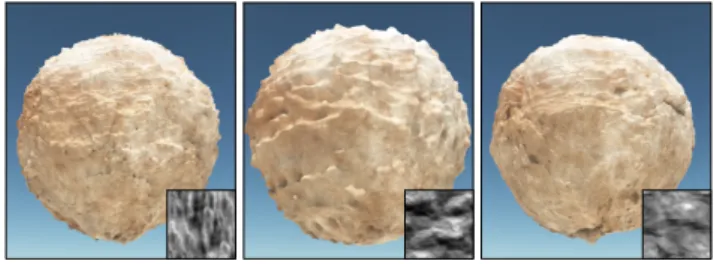
Fig. 9 Examples of gradient-based warping with different reliefs applied to a sphere primitive.
Surface details Adding surface details to implicit surfaces is a challenging problem as implicit surfaces do not provide an explicit parameterization. Existing methods rely either on interactive authoring [24] or re-quire an explicit parameterization of the implicit sur-face [29], and do not lend themselves for generating the surface details of blocks. We introduce a new gradient-based warping operator for adding details to any im-plicit surfaces, taking inspiration from tri-planar pro-jection [9]. This warping, applied for every block, does not require an explicit parameterization of the surface, and introduces small-scale volumetric details as dis-placements that enhance the model. Figure 9 shows the effect of warping with different relief functions d encoded as images. The operator is defined as:
Let g(p) = ∇b(p)/k∇b(p)k denote the normalized gra-dient. Let γi(p) : R3 → R2 denote the projection of
p on the i-th plane, namely xy, xz and yz. The func-tion δ(p) : R3 → R3 computes the 3D warping of p
according to a 2D displacement function d : R2
→ R: δ(p) = g(p) 3 X i=0 αi◦ g(p)) · d ◦ γi(p)
The weighting function αi: R3→ R weights the
contri-butions of the three displacements d ◦ γi(p) according
to the scalar product between the normalized gradient and the unit axis-aligned vectors ui: αi(p) = |g(p) · ui|.
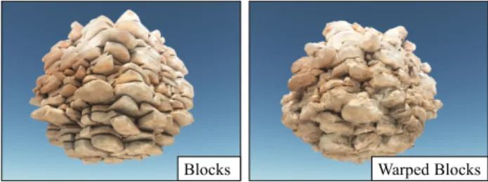
Blocks Warped Blocks
Fig. 10 Tabular block tile without warping (left) and after gradient-based warping (right): this new operator allows to create highly detailed blocks without holes.
The function d : R2 → R computes the displace-ment distance and can be effectively defined either as a procedurally defined turbulence, or from real displace-ment images. It is computed for every projection of the point p, thus three times. Figure 10 shows the effect of gradient warping for the tabular type.
5 Terrain amplification
The amplification process aims at generating a modified terrain eT = T ∪ R defined as the union of T and the replication R of some of the blocks Biin C over the bare
vertical walls of the cliffs. We propose a new replication operator transforming the initial scalar field f into an amplified model ef .
Infinite replication of a scalar field bi over the
en-tire space, first addressed in [23], can be obtained by directly computing bi with the modulo between the
argument point p and the size s of the tiling cube: bi(p mod s) with p mod s = p − s bp/sc. In our case,
the challenge consists of computing the scalar fields bi
only for the blocks Bi that straddle the terrain at
cer-tain positions, therefore according to the field function representing the terrain f . We employ a presence func-tion e : R3 → {0, 1} that evaluates whether a block B
i
should be replicated or not.
For every block Bi, we define a corresponding
an-chor point ai that will be used to evaluate its presence.
Here we present the concept with only one anchor point per block out of clarity, but the method can be easily generalized for a set of anchor points. Recall that bp/sc denote the integer coordinates of the virtual cell con-taining p. Blocks are selectively replicated by comput-ing the presence e function at the virtual anchor point in world space ai + s bp/sc. The replication operator
is a function t which defines its field function as the union of all block field function bi times their presence
function ei.
t(p) = max
i bi(p mod s) ei(ai+ s bp/sc)
The final function ˜f of the terrain is defined as ˜f = max(f, t).
More precisely, the evaluation of the replication op-erator at a point p is performed as follows. We evaluate in which cell of the grid lies p, using a modulo operation on the floating point coordinates of p. We compute the contribution of each block function bi, virtually
trans-lated in the cell for the point p.
If the distance from p to a border of a cell is less than a given threshold we compute the contribution in neighboring cells to account for blocks straddling C. Therefore, we compute the total contribution as the union between blocks in the current cell and 2, 4 or 8 neighboring cells.
In the case of a set A = {ak} of several anchor
points, the presence function ei computes the
percent-age of anchor points ai of Bi which satisfy geometric
criteria. In our implementation, we replicate a block if more than half, i.e. #A/2, of the anchor points satisfy e(ak) = 1.
The presence function can be any combination of a variety of criteria; here we briefly review some im-portant ones that allow for the automatic placement of blocks over the vertical walls, and that provide control by prescribing a geological strata definition as presented in [18].
We first define criteria based on the distance to the surface: in our model, a block can be replicated only if enough anchor points ak are in a given distance range
[va, vb] to the surface, i.e f (ak) ∈ [va, vb]. To only
repli-cate blocks on steep slopes and vertical walls, we com-pare the direction of the gradient with the up direction uz; recall that g denotes the normalized gradient of the
terrain, we set e(ak) = 1 if |g(p) · uz| < ε, with ε the
maximum slope parameter. Finally, we extend on the implicit geological function γ defined in [18] and define different bedrock material at different location in the scene. Therefore, an anchor point ak satisfies the
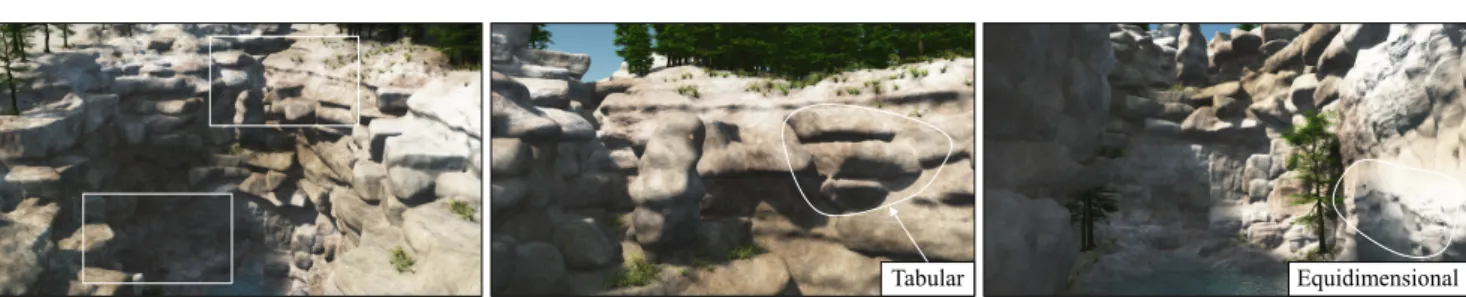
repli-Tabular Equidimensional
Fig. 11 A canyon amplified with equidimensional blocks located at the bottom of the canyon, and tabular blocks placed on the higher parts of the cliff walls.
cation criteria if the material γ(ak) corresponds to the
material of the underlying block Bi.
Note that the presence function is generic and can be easily extended to account for other criteria such as the presence of a water level, trees and obstacles.
6 Results
We implemented our method in C++ and all the scenes were generated on a desktop computer equipped with Intel R Core i7, clocked at 4 GHz with 16GB of RAM,
and an NVidia GTX 970 graphics card. The implicit surface representing the amplified terrain was polygo-nized [27] and the resulting mesh directly streamed into Vue Xstream R to produce the final images (Figures 5,
6, 9, 10, 11, 12, 13, 14).
Scene Figure Size #R Memory Sea cliff 1, 14 100 × 100 959 0.57 Canyon 11 100 × 50 1041 0.54 Sea spire 3 150 × 150 1680 0.53 Table 2 Statistics for the scenes: size (in meters), number of replicated blocks #R, and amount of memory (in megabytes) needed to store the field functions birepresenting the blocks
Biin the cubic tiles C.
Table 2 reports some statistics about the different scenes. Contrary to noise-based hyper-textures that only require a few dozens of parameters, our method needs to store the hierarchical implicit models of the different blocks; the required amount of memory remains small (less than a megabyte).
6.1 Control
Figure 5 a variety of types of blocks: different fractures distributions were prescribed (Section 4) and lead to different shapes such as polyhedral, rhombohedral or tabular blocks. The user can tune the parameters of
different fractures within a tile, and our method auto-matically computes block shapes that adapt to these constraints; it is also possible to sculpt specific blocks and let the system automatically adapt and generate the remaining ones, as demonstrated by Figure 6, where the user placed specific tabular or rhombohedral blocks at the desired locations in the tiles.
Figure 11 illustrates user-control over the block place-ment: an equidimensional bedrock strata was defined by the user at the bottom of the cliff resulting in regular cliff walls. A second strata with tabular type was pre-scribed above the previous one and tabular blocks were automatically added to account for the specified mate-rial. In practice, it takes a few iterations for the user to tune the placement rules of the different block tiles for a specific scene; the main limitation remains the com-putationally intensive visualization of the final implicit surface (see Section 6.4).
Figure 11 also demonstrates the effectiveness of con-trol based on the computation of the gradient ∇f for detecting the vertical parts of the terrain: no blocks were generated on the top of the plateau, thus keeping the ground flat where trees appear. Figure 14 shows different styles of blocks applied to a sea cliff scene, completely changing the overall mesoscale geometry of the final landscape.
Finally, micro-scale details are defined by using the gradient-based warping operator combined with differ-ent displacemdiffer-ent maps as showcased in Figure 9. The relief function d can be painted by the user; procedu-rally defined by combining noise functions in construc-tion tree of scalar primitives or scanned from real rock surfaces.
6.2 Comparison with other methods
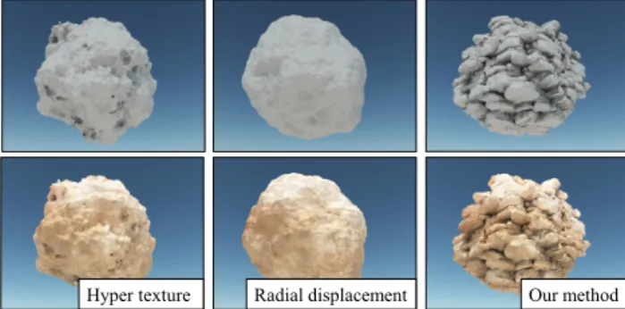
While the sum of scaled-noise functions [6] can, in the-ory, produce an infinite amount of details, the self-similar geometries resulting from the fractal process do not capture the characteristic structures and patterns observed on real terrains. Figure 12 shows a comparison
of different methods used to add details onto a sphere. Hyper-textures [20, 6] may generate holes and discon-nected parts, star-shaped primitives with a radial tur-bulence [18] avoids artifacts but both methods lack ological structure. In contrast, fracturing generates ge-omorphologically consistent blocks, and gradient-based warping allows for the generation of small-scale details captured from real rocks. Hyper-textures [20] could also be used to add small-scale details, however gradient-based warping allows for better control over the dis-placement by using reliefs from real rocks.
Hyper texture Radial displacement Our method
Fig. 12 Comparison of different methods used to add details onto an implicit sphere, with an ambient shading (top) and a high resolution texture (bottom).
In terms of mesoscale details, our method improves existing volumetric terrain models. Global warping op-erators [8] do not provide sufficient accuracy to repro-duce the complex geometry of the vertical parts of the bedrock. Voxels and features curves-based approaches [3] are limited by the grid resolution and generate smooth large-scale terrains.
While the system described in [18] can generate large scale landforms such as arches, overhangs, and simu-late large scale erosion effects, the vertical surface of cliffs lacks geometrical patterns and bedrock details. Although primitive-based implicit surfaces can theo-retically reproduce small-scale details, their modeling comes at the price of defining a huge number of small primitives in the construction tree, a memory-intensive process. In contrast, our method defines a memory-efficient tiling and replication function that implicitly tiles space with a union of blocks to amplify and add details to cliffs.
In spirit, generating and replicating instances resem-bles the Ghost Tiling approach [11], and the rock pile generation based on aperiodic tiling [21] that instan-tiate rock meshes. Our approach differs in the sense that blocks are defined as implicit primitives and virtu-ally replicated by using a replication operator combined with a presence function, which allows us to combine them to produce a consistent volumetric model.
More-over, these methods would need to be improved to ac-count for fracture distributions to guarantee the repli-cability of certain block types - which is one primary focus of our work.
6.3 Compatibility with other techniques
An important aspect of this work is that it is compati-ble with other terrain modeling techniques. Our method can benefit to implicit surface-based terrain representa-tions such as the hybrid layer-stack convolution-surface framework described in [22] or the primitive-based sys-tem [18]. Those models, designed for modeling large scale terrains, can be amplified with mesoscale details as demon-strated in Figure 13. Moreover, our method lends itself to amplifying heightmaps or procedurally defined ele-vations since a three-dimensional scalar field f : R3→
R can be directly derived from the elevation function h : R2→ R by defining f(p) = pz− h(pxy).
Arches Our method
Fig. 13 Side by side comparison showing a canyon with smooth overhangs produced by the layer-stack model, and the rocky amplified vertical-wall generated by blocks.
Finally, although we used implicit surfaces for mod-eling the complex mesoscale 3D features of terrains, the block generation algorithm (Section 4) can also produce a mesh representation Mkfor every block Bkin the tile.
In this context, our method can be streamed in pro-duction environments using mesh representations and is compatible with standard instantiation techniques such as the ones described in [21] or [11] to distribute block meshes over the vertical parts of the input terrain.
6.4 Limitations
The block tile generation process (Section 4) can take up to 30s because of the many intersection tests be-tween segments (linking two points in the tile) and frac-tures discs. However, time was not spent on optimizing
Tabular Equidimensional Rhombohedral
Fig. 14 Different styles of blocks generated on a cliff and arches. From left to right, tabular block style, equidimensional blocks and finally rhombohedral block style.
this step of our pipeline, since it is done once in pre pro-cessing. A more limiting property of our method is the fact that our block primitives can only model convex shapes. This could be resolved by developing primitives more suited for non-convex shapes, but it is beyond the scope of this paper and is left as future work.
Although implicit surfaces provide a powerful, sparse, and compact framework for generating complex volu-metric structures, their visualization remains compu-tationally intensive. In particular, the computation of the field function bi for one single block Bi requires
many half space distance computations, combined with a warping operator: blocks could be optimized with a limited number of primitives to reduce the overall num-ber of field function queries.
Using a limited set of block tiles sometimes yields visible repetitions when applied to flat cliff walls paral-lel to the tiling directions. Aperiodic tiling using Wang cubes [4] or Corner Cubes [14, 22] would reduce visible artifacts, yet at the price of a larger number of pre-computed tiles and, therefore, a more memory demand-ing implementation.
Finally, the procedural fracturing tool only provides an indirect control over the distribution of fractures, and thus the shape of the blocks: a better interactive material editing tool would allow the user to author a wider range of shapes conforming to his intent.
7 Conclusion
We have introduced an implicit representation of blocks for automatically generating mesoscale and microscale details on the vertical walls of rocky cliffs, crags, or promontories. Our method relies on the decomposition of a bedrock tile into blocks using a fracturing ap-proach based on classifications in geomorphology. The implicit surface description allows generating realistic shapes enhanced with details organized into patterns and structures as observed in geomorphology. Our method is compatible with other terrain modeling techniques: the block generation algorithm can additionally pro-duce triangle meshes, which in turn can be instantiated
to enhance heightfields. We also introduced a warping operator that can be applied to any implicit surface model to add small-scale details.
A direct extension of this work would consist of generalizing with different types of blocks, in particu-lar prismatic and columnar configurations that require specific fractures distributions. Another avenue of re-search worth investigating would be to generate large-scale fractures spreading over hundreds of meters and shaping the vertical walls of cliffs by taking into account the underlying strata of the bedrock.
Conflict of Interest
The authors declare that they have no conflict of inter-est.
Acknowledgments
This work was part of the project HDW ANR-16-CE33-0001, supported by Agence Nationale de la Recherche.
References
1. Barthe, L., Gaildrat, V., Caubet, R.: Combining implicit surfaces with soft blending in a CSG tree. CSG Confer-ence Series pp. 17–31 (1998)
2. Beardall, M., Farley, M., Ouderkirk, D., Reimschussel, C., Smith, J., Jones, M., Egbert, P.: Goblins by spheroidal weathering. In: Proceedings of Third Eurographics Con-ference on Natural Phenomena, pp. 7–14 (2007) 3. Becher, M., Krone, M., Reina, G., Ertl, T.: Feature-based
volumetric terrain generation and decoration. IEEE Transactions on Visualization and Computer Graphics 25(2), 1283–1296 (2019)
4. Culk, K.: An aperiodic set of 13 wang tiles. Discrete Mathematics 160(1-3), 245–251 (1996)
5. Dearman, W.: Engineering geological mapping. But-terworths advanced series in geotechnical engineering. Butterworth-Heinemann (1991)
6. Ebert, D.S., Musgrave, F.K., Peachey, D., Perlin, K., Worley, S.: Texturing and Modeling: A Procedural Ap-proach, 3rd edn. The Morgan Kaufmann Series in Com-puter Graphics. Elsevier (1998)
7. Galin, E., Gu´erin, E., Peytavie, A., Cordonnier, G., Cani, M.P., Benes, B., Gain, J.: A review of digital terrain mod-eling. Computer Graphics Forum (proceedings of Euro-graphics 2019 STAR) 38(2), 553–577 (2019)
8. Gamito, M.N., Musgrave, K.F.: Procedural landscapes with overhangs. In: Proc. of the Portuguese Computer Graphics Meeting. Lisbon, Portugal (2001)
9. Geiss, R.: Generating complex procedural terrains using the GPU. In: GPU Gems 3, chap. 1, pp. 7–37. Addison-Wesley (2008)
10. Gourmel, O., Barthe, L., Cani, M.P., Wyvill, B., Bern-hardt, A., Paulin, M., Grasberger, H.: A gradient-based implicit blend. ACM Transactions on Graphics 32(2) (2013)
11. Gu´erin, E., Galin, E., Grosbellet, F., Peytavie, A., G´enevaux, J.D.: Efficient modeling of entangled details for natural scenes. Computer Graphics Forum (Proceed-ings of Pacific Graphics 2016) 35(7), 257–267 (2016) 12. Ito, T., Fujimoto, T., Muraoka, K., Chiba, N.: Modeling
rocky scenery taking into account joints. In: Proceedings of Computer Graphics International, pp. 244–247. IEEE, Tokyo, Japan (2003)
13. Jones, M., Farlay, M., Butler, M., Beardall, M.: Di-rectable weathering of concave rock using curvature esti-mation. IEEE Transactions on Visualization and Com-puter Graphics 16(1), 81–97 (2010)
14. Lagae, A., Dutr´e, P.: An alternative for Wang tiles: Col-ored edges versus colCol-ored corners. ACM Transactions on Graphics 25(4), 1442–1459 (2006)
15. Ma, C., Wei, L.Y., Tong, X.: Discrete element textures. ACM Trans. Graph. 30(4) (2011)
16. Neyret, F.: Modeling animating and rendering complex scenes using volumetric textures. IEEE Transactions on Visualization and Computer Graphics 4(1), 55–70 (1998) 17. Palmstrom, A.: Measurement and characterization of
rock mass jointing, pp. 49–97 (2001)
18. Paris, A., Galin, E., Peytavie, A., Gu´erin, E., Gain, J.: Terrain amplification with implicit 3D features. ACM Transactions on Graphics 38(5), 147:1–147:15 (2019) 19. Perlin, K.: An image synthesizer. SIGGRAPH Computer
Graphics 19(3), 287–296 (1985)
20. Perlin, K., Hoffert, E.M.: Hypertexture. SIGGRAPH Computer Graphics 23(3), 253–262 (1989)
21. Peytavie, A., Galin, E., Grosjean, J., M´erillou, S.: Proce-dural Generation of Rock Piles Using Aperiodic Tiling. Computer Graphics Forum 28, 1801–1809 (2009) 22. Peytavie, A., Galin, E., M´erillou, S., Grosjean, J.: Arches:
A framework for modeling complex terrains. Computer Graphics Forum 28(2), 457–467 (2009)
23. Stolte, N.: Infinite implicit replication: Case study for voxelizing and representing cyclical parametric surfaces implicitly. Shape Modeling International’02, pp. 105–111 (2002)
24. Sugihara, M., Wyvill, B., Schmidt, R.: Warpcurves: A tool for explicit manipulation of implicit surfaces. Com-puters & Graphics 34(3), 282–291 (2010)
25. Worley, S.: A cellular texture basis function. SIGGRAPH 96, pp. 291–294 (1996)
26. Wyvill, B., Guy, A., Galin, E.: Extending the CSG tree – Warping, Blending and Boolean Operations in an Im-plicit Surface Modeling System. Computer Graphics Fo-rum 18(2), 149–158 (1999)
27. Wyvill, G., McPheeters, C., Wyvill, B.: Data structure for soft objects. The Visual Computer 2, 227–234 (1986) 28. Yuksel, C., Lefebvre, S., Tarini, M.: Rethinking texture mapping. Computer Graphics Forum 38(2), 535–551 (2019)
29. Zanni, C., Bares, P., Lagae, A., Quiblier, M., Cani, M.P.: Geometric Details on Skeleton-based Implicit Surfaces. In: Eurographics Short Papers, pp. 49–52. Cagliari, Italy (2012)