HAL Id: hal-01799026
https://hal.archives-ouvertes.fr/hal-01799026
Submitted on 24 May 2018
HAL is a multi-disciplinary open access
archive for the deposit and dissemination of
sci-entific research documents, whether they are
pub-lished or not. The documents may come from
teaching and research institutions in France or
abroad, or from public or private research centers.
L’archive ouverte pluridisciplinaire HAL, est
destinée au dépôt et à la diffusion de documents
scientifiques de niveau recherche, publiés ou non,
émanant des établissements d’enseignement et de
recherche français ou étrangers, des laboratoires
publics ou privés.
Numerical simulation of thermal fatigue behavior in a
cracked disc of AISI H-11 tool steel
Faisal Qayyum, Masood Shah, Osama Shakeel, Fariha Mukhtar, Mehdi Salem,
Farhad Rezai-Aria
To cite this version:
Faisal Qayyum, Masood Shah, Osama Shakeel, Fariha Mukhtar, Mehdi Salem, et al.. Numerical
simulation of thermal fatigue behavior in a cracked disc of AISI H-11 tool steel. Engineering Failure
Analysis, Elsevier, 2016, 62, pp.242-263. �10.1016/j.engfailanal.2016.01.015�. �hal-01799026�
Numerical simulation of thermal fatigue behavior in a cracked
disc of AISI H-11 tool steel
Faisal Qayyum
a,⁎
, Masood Shah
a,b, Osama Shakeel
a, Fariha Mukhtar
a,
Mehdi Salem
b, Farhad Rezai-Aria
baDepartment of Mechanical Engineering, University of Engineering and Technology, Taxila, Pakistan
bUniversité de Toulouse; INSA, UPS, Mines Albi, ISAE; ICA (Institut Clément Ader) Route de Tiellet, Campus Jarlard, Albi, France
a b s t r a c t
Thermal fatigue is one of the key reasons of material failure in components which are exposed to high temperature cycles. Prediction of crack initiation site and crack propagation speed dur-ing thermal cycldur-ing helps us predict the life of a component in service. In this research numer-ical simulation of crack propagation due to thermal cycling on a circular disc has been carried out. The thermal profiles used in the simulation are taken from actual thermal fatigue experi-ments. The effect of the length of cracks and interaction between adjacent cracks has been in-vestigated. 50 sets of numerical simulation models with different crack numbers and crack lengths have been simulated. The variation in Stress Intensity Factor (SIF), hoop stress and Crack Mouth Opening Displacement (CMOD) has been plotted as a function of primary/second-ary crack lengths and number of cracks. Envelopes of possible crack growth have been identi-fied and correspond well to the experimental observations. Results show a significant drop in hoop stress, SIF and CMOD with increase in number of cracks, thus limiting the number of cracks possible in a thermal fatigue crack network.
Keywords: Thermal fatigue Crack propagation Numerical simulation Stress Intensity Factor Crack arrest
1. Introduction
Thermal fatigue is one of the key damage mechanisms in applications involving high temperatures like in power plants, engine valves, gas turbines, steam valves, nuclear reactors, high pressure die casting, and forging operations. Currently no standard pro-cedure for thermal fatigue testing exists. The inherent complexity of thermal fatigue problem, renders standardization of this test-ing procedure almost impossible.
Different researchers have developed their own specific experimental setups, closely resembling the application being investi-gated. Some of the setups include a disc heated by induction on the periphery[1–12], triangular blade heated by induction[13], electrical heating of tube followed by water splashing to induce thermal shock[14–18], hot dipping of cylinders in molten alumi-num[19,20], laser heating[21,22], focused halogen lamps heating[23,24], convection/combustion heating[25,26], furnace heating with water quenching[27,28]and actual dies[29,30]. Out of these experimental setups most researchers have worked on the heated disc problem. Analytical models have been developed for heated disc type configuration using Stress Intensity Factor “ΔK” [31–35], for this purpose Mowbray et al.[31]used ΔK based on the weight function defined by Bueckner to characterize
⁎ Corresponding author at: Fracture Mechanics and Fatigue Lab., Mechanical Engineering Department, University of Engineering and Technology, Taxila, Punjab, Pakistan.
the thermal fatigue crack propagation[36]. Others used cyclic J integral[37,38]and strain intensity factor[32–35,39,40]for char-acterizing thermal fatigue crack propagation. Most researchers deal with thermal fatigue as a special case of isothermal fatigue. Many researchers have worked on numerical simulation models[41–43]to create better understanding of thermo-mechanical stresses which are produced during the process and are responsible for failure of components.
Thermal fatigue is considered to be composed of two components, initiation phase and the propagation phase. It has been in-vestigated that the initiation might occur due to oxidation sites or due to plasticity, as in the case of stainless steels [unpublished internal results on thermal fatigue of 316 stainless steel, ecole mines albi]. One of the observations made during experimentation was that two diametrically opposed cracks initiate and propagate with almost the same speed through the specimens as repre-sented inFig. 1schematics. Secondary cracks are created later and their propagation speed is lower than the primary cracks. The total number of cracks (primary and secondary) almost never exceeds 8 in number in oxidizing steel. This material was cho-sen because due to oxidation large number of cracks initiate, while the cracks having sufficient SIF propagate during thermal cy-cling. This phenomenon has been presented inFig. 1.
This research aims to determine the interaction between primary and secondary cracks. It also aims to determine the thresh-old value of number of secondary cracks that can propagate. The threshthresh-old value is found to be dependent on the stress relaxation produced due to addition of secondary cracks around the periphery of the specimen.
All in all 50 simulation models with different crack number and crack lengths were run to determine the threshold of crack number. The drop in SIF, hoop stress and CMOD is plotted as a function of number of cracks and primary/secondary crack lengths. These plots give an envelope of propagation, clearly showing the parameters necessary for the crack propagation to occur. The results obtained were observed to be in agreement with the experimental observations.
Fig. 1. Crack initiation and propagation in an oxidizing steel.
Nomenclature Acronyms
SIF Stress Intensity Factor
CMOD Crack Mouth Opening Displacement
CTOD Crack Tip Opening Displacement
List of symbols
ap primary crack length
as secondary crack length
ap max maximum length of primary crack
as max maximum length of secondary crack
n number of cracks
σH hoop stress
2. Experimentation
The experimentation was done by Salem M.[44]in his PhD thesis, and detailed material model for AISI H11 tool steel which have been incorporated in the numerical simulation model were developed by Ahmer[45]. The experimental setup and geometry of the used specimen is shown inFig. 2. Heating was done by induction coils while cooling was done by cold water flowing through internal pipe at 25 °C. 6 thermocouples were spot welded on the disc at positions specified inFig. 3. This specimen was heated using an induc-tion heating system with 1.3 s heating cycle and 7.2 s cooling cycle. The resulting thermal profile is shown inFig. 3and is compared with the thermal profile obtained from simulation. The cracks were observed and measured using binocular microscope during test-ing, which helped in determining fatigue crack propagation rate and crack locations.
3. Numerical simulation
Numerical simulation was carried out on ABAQUS Standard™ 6.12. Decoupled thermo-mechanical approach was adopted dur-ing simulation. Simulations were carried out for a disc type specimen on a pipe configuration. Sectioned model of the assembly is shown inFig. 2(b). Thermal analysis was carried out for 10 thermal cycles to obtain steady state results which will be discussed
Fig. 2. (a) Experimental setup. (b) Specimen Shape (all dimensions are in mm)[44].
later. Temperature change of each node was recorded after specific time intervals. Saved temperature changes at each node at specific time intervals were fed to the stress analysis file as an input. Results of stress development and crack opening during thermal cycling were observed.
Due to thermal cycling hundreds of microcracks develop on the surface of the specimen (upper left of Fig. 1). These microcracks are shown to be formed due to the presence of oxidation at the surface of the specimens. Some of these microcracks later develop into macro cracks (lower right ofFig. 1) and propagate through the section of the specimen. The primary cracks (minimal of 0.5 mm length), as they are called are the diametrically opposed cracks that appear initially and are always longer in length than the other cracks on the periphery of the specimen.
3.1. Material data
Specimen was made of AISI H-11 hot work tool steel with chemical composition as shown inTable 1. Density of 7840 kg/m3
and a Poisson's ratio of 0.3 were used. The temperature dependent properties used during simulation are shown inFig. 4. 3.2. Thermal analysis
The disc part of the specimen inFig. 2(b) was modeled as a 2D deformable shell of 30 mm outer diameter and 18 mm inter-nal diameter with a thickness of 1 mm. The hollow shaft inside was modeled as a 2D deformable shell of 18 mm outer diameter and 12 mm internal diameter having length 40 mm as shown inFig. 5. Temperature dependent material properties of H11 tool steel (Fig. 4) were assigned to the material model. Both instances were assembled together in the assembly module by using co-axial constraint command. Transient heat transfer model was selected in step module for 10 thermal cycles giving a total time period of 85 s for the analysis. Heat sink of 25 °C was applied inside shaft. While defining boundary conditions, external surface of shaft and internal surface of disc were constrained with “tie interaction” of continuous heat transfer condition. Surface heat flux of 5.15 W/mm2was applied on the outer rim of flange with amplitude shown inFig. 3. InFig. 3, 1 means maximum flux and 0
means no flux. The amplitude profile values were adjusted so that the thermal profile obtained by simulation at different points along the radius of the disc matches the thermal profile in the experimentation. This indirectly takes into account the heating due to the induction coil, radiative losses, natural convection losses as well as the conduction loss due to the cooling channel. The comparison between experimental and numerical values is shown inFig. 3. Close correlation exists up to a depth of 2 mm. After that the experimentation shows almost 20% higher temperatures than the numerical simulation. The amplitude follows the response of the induction heating system.
The meshed assembly is shown inFig. 5. It was assured that aspect ratio of all elements is almost equal to 1. The model was also checked for mesh dependency. The simulation model schematic is shown inFig. 5. The thermocouple positions inFigs. 3and
5were used to calibrate the thermal model. 3.3. Stress and fracture analysis
For mechanical analysis the disc and shaft again modeled as 2D deformable shells with all properties as discussed in the
Material datasection. Temperature dependent material properties of H11 tool steel were assigned to the disc and shaft. An incre-mental plasticity model was used for the plastic deformation of the specimen.
The primary and secondary cracks of different lengths and numbers were modeled on disc using surface partition command. The choice of crack lengths follows the experimental observations. Initially the experiments were conducted on H11 steel. This steel develops an oxide scale due to thermal cycling and the detection of a crack under this scale was difficult. Also the crack ini-tiation point is on the curve of the specimen. Both these factors affect the minimum resolution of the crack observations which is 0.5 mm using a binocular microscope. (Observations with higher powered microscopes are difficult due to low depth of field of the microscopes and heavily instrumented specimen, which has 6 thermocouples of 0.1 mm thickness spot welded on the surface).
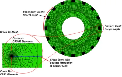
Once the resolution is identified a complete range of possibilities of crack lengths is simulated. The only constraint was that the primary crack has to be longer than the secondary crack length. A 16 cracks numerical simulation set containing 1 primary crack of 2 mm length and 15 secondary cracks of 0.5 mm length is shown inFig. 6. Cracks were defined in assembly module using contour integral command. Collapsed element side seam with mid side node parameter of 0.24 was defined for all cracks. The set of cracks defined during simulation are shown inTable 2. Static general model was selected in step module for time pe-riod of 85 s which simulates 10 thermal fatigue cycles. It was observed that although the thermal profile stabilizes at the third cycle, the stress–strain response and the J-integral does not stabilize up to the 7th cycle. It was thus decided to run the thermal fatigue experiments up to 10 cycles so that stability in mechanical response can be assured. Due to cyclic simulation the crack faces come into contact during the simulation. The crack faces were defined as contact pairs with frictionless contact to avoid
Table 1
Chemical composition of AISI H-11 tool steel.
Elements Cr Mo Si V C Ni Cu Mn P S
Fig. 4. Temperature dependent material data of H-11 tool steel[44,45].
any elemental penetration during the simulation. Coefficient of friction is considered as frictionless because in mode I crack no sliding occurs. Since the simulation model is based on mode I crack opening configuration, keeping in view the simplicity of the model, the effect of sliding was not considered and hence frictionless contacts were defined.
The detailed meshing for crack tip is given elsewhere[46]. The meshed assembly is shown inFig. 6. In total, 1 thermal and 49 mechanical simulation models were run to achieve the desired results.
4. Results and discussion
Thermal fatigue is caused by thermal gradients in a component which results in material expansion and strains eventually resulting in production of thermal stresses in the component due to the constraint of the material itself. The phenomenon is ma-jorly strain controlled deformation. As a consequence the largest strains and stresses occur at the surface with thermal cycling, because of which a large number of cracks initiate at the surface. When the components (in this case a disc) develop cracks, its compliance increases, which leads to reduction of the stresses and strains. When this happens the formation of new cracks be-comes less likely and the propagation of individual macro-cracks is reduced. The reduction in stresses/strains is directly linked to the circumferential distance between cracks and the crack depth, which results in a typical number of cracks. Due to the thermal gradients the stresses also decay with the distance from the heated surface. As a consequence crack propagation rate slows down and crack often arrests at a specific depth.
Numerical simulation gives us an insight of how heat transfer takes place during each cycle, and in response to cyclic thermal fa-tigue how mechanical stresses are produced in the disc. It is also observed how number of cracks (n) and crack lengths (asand ap)
affect the stresses produced in the disc. The thermal cycle stabilizes typically at the third cycle in simulation and experimentation alike.Fig. 3also shows the comparison of the experimental and numerical thermal response and a good correlation is observed. In this section the stress–strain response is discussed followed by the effects of multi-cracking on the stress distribution and J-integral ahead of the crack tip.
Fig. 6. Meshed assembly of simulation set containing 1 primary crack of 2 mm length and 15 secondary cracks of 0.5 mm length.
Table 2
Set of cracks defined during simulation. Number of cracks
(n)
Length of primary crack (ap)
Length of secondary cracks (as)
Total number of simulations
1 0.5, 1, 2, 3, 4 0 5 2 0.5, 1, 2, 3, 4 0.5 11 2, 3, 4 1 3, 4 2 4 3 4 0.5, 1, 2, 3, 4 0.5 11 2, 3, 4 1 3, 4 2 4 3 8 0.5, 1, 2, 3, 4 0.5 11 2, 3, 4 1 3, 4 2 4 3 16 0.5, 1, 2, 3, 4 0.5 11 2, 3, 4 1 3, 4 2 4 3
4.1. Stress–strain response
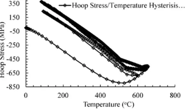
The stress–strain response is studied initially on the un-cracked disc. This response is important in determining the crack ini-tiation sites. Isotropic hardening temperature dependent material model was used. The first cycle shows a large amount of plastic deformation in compression. The initial heating results in expansion of the material which results in axial compression of flange, and the compressive stress increases till the temperature reaches 525 °C. Beyond this temperature, although the expansion con-tinues, the yield strength of the material starts to drop. 550 °C presents the first tempering temperature of this material and is also considered to be the limit of hot hard behavior. This softening results in a large amount of plastic deformation and reduction in compressive stress, visible is hoop stress vs temperature plotFig. 7. The drop in stress is substantial, from 820 MPa to 530 MPa compressive.
As the disc cools, a tensile residual stress is observed due to yielding in the first cycle. It is believed that this tensile residual stress is responsible for the thermal fatigue cracking in metals. After the first few cycles, the plastic deformation is greatly reduced and the stress–strain curve stabilizes. However, there is some amount of plastic deformation in each cycle. This plastic deforma-tion eventually causes enough damage to initiate thermal fatigue cracks.
4.2. Drop of tensile stress in flange due to multiple cracks
The presence of cracks affects the hoop stresses produced at the edge of the disc.Fig. 8(a, b, c, d) represents the smallest pri-mary crack length and secondary crack length of the simulation. Minimal (almost non-existent) effect of increase in number of cracks (n) on the periphery of the disc during compression cycle is observed. However, the effect of the number of cracks (n) on the tension part of the stress–strain response is significant. InFig. 8(a) it can be observed that there is a drop in tensile stress where the cracks are present. However, between these points there is a large “plateau” of constant tensile stress. For 4 cracks (Fig. 8(b)) the “plateau” still exists, however the maximum value of the tensile stress slightly drops. It is seen that for 8 cracks (Fig. 8(c)) there is almost no constant stress zone left on the periphery of the crack. Also, the value of the maximum tensile stress drops from 340 MPa to 320 MPa. This shows that the tensile stress peaks (that would exist in case of the un-cracked specimen) are now completely relieved by the 8 cracks around the periphery. A further increase in the number of cracks to 16 (Fig. 8(d)) reduces the tensile stress peaks to 280 MPa and there is no “plateau” showing that the tensile stress that initially caused the crack initiation cannot be achieved now. This is in agreement with experimental results [44]where the maximum number of cracks ever achieved never cross 8.
Fig. 9shows the comparison for long cracks as well. It is seen that for maximum crack length the tensile stress values drop to 120 MPa in the case of 16 cracks, thus eliminating any possibility of having more than 8 cracks to propagate around the periphery. The difference in compressive stresses between ap= 1 mm (lower compressive stress) and ap= 4 mm (higher compressive
stress) is due to the numerical model that has been used. The contact of the crack faces is necessary to accurately simulate the compressive stresses. In the numerical model, contact of the crack faces is made except for the last element of the crack tip. Here the contact cannot be defined because the upper and lower face has an intersecting point (crack tip). During simulation, the crack tip elements cross each other. The simulation generally gives satisfactory results because the area represented by the crack tip is much lesser than the total crack faces. But in the case of very short cracks, the effect of this (non-contact definition) is slightly more pronounced. The effect is manifested as a lower compressive stress simulated. In the extreme cases as is shown in
Fig. 9this error is almost 8%.
The J-integral calculations are important during the tensile cycle of the TF experiment. This difference of compressive stress might not greatly affect the J-integral values.
4.3. J-integral as a function of crack length
Once the cracks initiate, they will continue to propagate under the effects of the tensile stress. The crack propagation speed has been found to be fast up to 1 mm crack length and slows down considerably afterwards. The primary crack propagation arrests at
a length of 3.5 mm maximum while the secondary cracks rarely exceed 2.5 mm in length.Fig. 10 [44]shows some of the results obtained experimentally (in this case only five cracks were tracked while others do exist, but they were not tracked).
4.4. Development of crack tip stress field
When a crack is introduced into the periphery, it initially acts as an un-cracked ligament during the first heating cycle. Follow-ing this durFollow-ing the coolFollow-ing cycle the initial yieldFollow-ing at the highest temperature causes tensile stresses which open the crack as shown in theFig. 11. The second cycle causes crack closure (forward yielding) and then during subsequent cooling (second cycle) a more severe crack opening is observed.
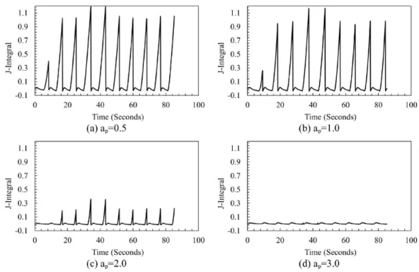
The contour integral plot inFig. 12represents the development of crack tip stress field. Sharp rise in the second cycle as com-pared to the first cycle is indicative of the residual crack opening created due to first yielding of the cracked specimen (Fig. 12). The numerical simulation of the contour integral shows that the J-integral remains constant, (and high) up to 1 mm crack length (Fig. 12). Beyond this point the value sharply reduces and is minimal at 3 mm crack length. At 4 mm crack length the value is almost zero, indicating that there is not much possibility of crack growth at this crack length. This fact is experimentally verified with experimentally obtained crack lengths[44].
Fig. 8. Distribution of hoop stress along periphery of the flange.
4.5. Envelopes of crack propagation
The effect of the number of secondary cracks of 0.5 mm length on the J-integral of the primary crack is shown in the surface plot inFig. 13(a). The red and light blue shades within 0 ≤ n ≤ 7 (where n = number of secondary cracks) shows the envelope of propagation. Beyond n = 7 there is a sharp drop in the J-integral value that would arrest any crack. Also beyond ap= 3 mm the
J-integral value drops to zero, indicating that no propagation is possible. Parallel surfaces can be obtained for different values of as.
In the same manner the J-integral surface plot for the other extreme condition with ap= 4 mm and different asis shown in
Fig. 13(b). It is clear here that the blue part of the surface indicates the zone of non-propagation. This surface shows that the maximum secondary crack length could not exceed 2.5 mm. Practically this observation seems to be true by experimental verifi-cation[44].
Fig. 10. Crack growth in disc specimen. Primary cracks are longer than the secondary cracks. apmax= 3.5 mm, asmax= 2.5 mm. Cracks accelerate up to 1 mm
length[44].
4.6. CMOD as a function of apand as
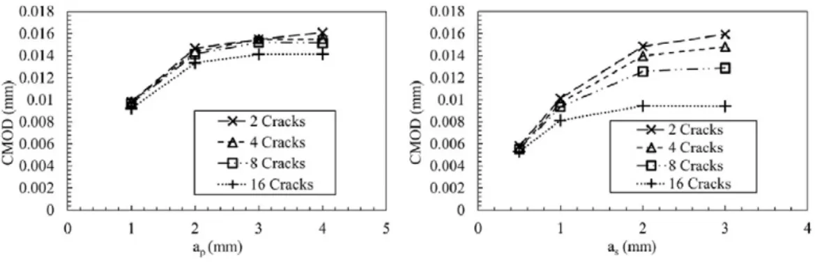
Numerous researchers have worked on relating the fatigue crack growth rate to cyclic J-integral[47–49] [50]and to the Crack Tip Opening Displacement (CTOD)[24,51–54]. The ASTM standard E399[55]also gives an indirect crack length measurement method using the CMOD. The CMOD values were thus extracted for the different thermal cycles to see if they represent the J-integral values at the crack tip as shown inFig. 14(a) and (b).
It is seen that the CMOD values of the primary or secondary crack do not represent at all whatever is happening at the crack tip. The values of the CMOD increase continuously while the crack propagation rate and J-integral drop continuously during the propagation beyond 1 mm crack length. The CMOD values do not change a lot even for 16 cracks when the secondary cracks have small length (Fig. 14(a)). CMOD values for 16 cracks shows a sharp decline, which is representative of stress relaxation around the periphery for longer crack lengths.
5. Conclusion
The study to verify the limiting number of cracks produced on the rim of an H11 tool steel disc exposed to thermal fatigue was carried out using numerical simulation technique. Decoupled thermal mechanical numerical simulation technique was successful-ly used to get an insight of a thermal fatigue phenomenon. Thermal profiles were taken from actual thermal fatigue experiments. Isotropic hardening temperature dependent material model was used. 50 sets of numerical simulation models with different crack numbers and crack lengths were simulated to determine the interaction between the primary and secondary cracks. Significant
Fig. 12. J-integral stabilization graph when primary crack length ap= 0.5, 1.0, 2.0 and 3.0 mm.
drop in hoop stress and SIF with increase in number of cracks was observed. Envelopes of crack propagation were determined by plotting surface plots of J-integral as a function of n, apand as.
1. It was observed that the initial heating causes expansion of the material which results in axial compression of flange, and the compressive stress increases till the temperature reaches 525 °C. Beyond this temperature yield strength starts to drop which softens the material and results in drop of compressive stress. 35% drop in compressive stress was observed for first cycle in
Fig. 7(from 820 MPa to 530 MPa compressive) which is considered to be the most damaging.
2. It is obvious that crack initiation and propagation in the disc occurs due to tensile stresses. It was observed that increases in number of cracks produced in the disk substantially decreases maximum tensile stresses on the rim which limits the number of cracks produced due to the phenomena of stress relieving. In the current scenario it was observed that the number of cracks propagating will never exceed 8.
3. It was observed that crack tip stress field fully develops after multiple fatigue cycles. It was also observed that value of J-integral on crack tip decreases with increase in crack length. To elaborate this phenomenon of crack arrest surface plots of J-integral as a function of n, apand as were developed to find the crack propagation envelopes for primary and secondary
crack lengths. As the maximum number of cracks never cross the value of 8 the primary crack length never exceeds 3 mm and secondary crack lengths never cross 2.5 mm. n ≤ 8, ap≤ 3 mm and as≤ 2.5 mm, these are considered to be the threshold
values.
4. It was observed that although the value of J-integral drops as the crack length increases, the CMOD keeps on increasing. It is concluded that in the current scenario CMOD does not represent a good measure of the crack tip stresses.
Acknowledgment
Experimentation of this research was conducted at the Université de Toulouse; INSA, UPS, Mines Albi, ISAE; ICA (Institut Clém-ent Ader) Route de Tiellet, Campus Jarlard, Albi, France. The simulation was done at the Fracture Mechanics and Fatigue Lab., De-partment of Mechanical Engineering, University of Engineering and Technology Taxila (UET/ASR&TD/RG-1250 and UET/ASR&TD/ RG-348), Pakistan. The study was funded and supported by both institutes which are gratefully acknowledged.
Appendix A. Supplementary data
Supplementary data to this article can be found online athttp://dx.doi.org/10.1016/j.engfailanal.2016.01.015. References
[1] S. Le Roux, et al., Image analysis of microscopic crack patterns applied to thermal fatigue heat-checking of high temperature tool steels, Micron 44 (0) (2013) 347–358.
[2] M. Kamaya, M. Kawakubo, Loading sequence effect on fatigue life of Type 316 stainless steel, Int. J. Fatigue 81 (2015) 10–20.
[3] F. Szmytka, et al., Thermal fatigue analysis of automotive diesel piston: experimental procedure and numerical protocol, Int. J. Fatigue 73 (0) (2015) 48–57.
[4] K. Kuwabara, A. Nitta, Thermal-mechanical low-cycle fatigue under creep-fatigue interaction on type 304 stainless steels, Fatigue Fract. Eng. Mater. Struct. 2 (3) (1979) 293–304.
[5] C. Robertson, M.C. Fivel, A. Fissolo, Dislocation substructure in 316 L stainless steel under thermal fatigue up to 650 K, Mater. Sci. Eng. A 315 (1–2) (2001) 47–57.
[6] A. Persson, S. Hogmark, J. Bergström, Simulation and evaluation of thermal fatigue cracking of hot work tool steels, Int. J. Fatigue 26 (10) (2004) 1095–1107.
[7] J. Sjöström, J. Bergström, Thermal fatigue testing of chromium martensitic hot-work tool steel after different austenitizing treatments, J. Mater. Process. Technol. 153–154 (0) (2004) 1089–1096.
[8] A. Persson, S. Hogmark, J. Bergström, Thermal fatigue cracking of surface engineered hot work tool steels, Surf. Coat. Technol. 191 (2) (2005) 216–227.
[9] E. Paffumi, K.F. Nilsson, N.G. Taylor, Simulation of thermal fatigue damage in a 316 L model pipe component, Int. J. Press. Vessel. Pip. 85 (11) (2008) 798–813.
[10] A. Fissolo, et al., Crack initiation under thermal fatigue: an overview of CEA experience. part I: thermal fatigue appears to be more damaging than uniaxial iso-thermal fatigue, Int. J. Fatigue 31 (3) (2009) 587–600.
[11] S. Le Roux, et al., Role of heat-flux density and mechanical loading on the microscopic heat-checking of high temperature tool steels under thermal fatigue ex-periments, Int. J. Fatigue 51 (2013) 15–25 (0).
[12] F. Medjedoub, et al., Effect of local stress on the heat-checking morphology in high temperature tool steels under thermal fatigue: transition from multi-axiality to uniaxiality, Mech. Mater. 69 (1) (2014) 159–172.
[13] F. Rezai-Aria, L. Remy, An oxidation fatigue interaction damage model for thermal fatigue crack growth, Eng. Fract. Mech. 34 (2) (1989) 283–294.
[14] A. Fissolo, et al., Thermal fatigue behaviour for a 316 L type steel, J. Nucl. Mater. 233–237 (Part 1) (1996) 156–161 (0).
[15] N. Haddar, A. Fissolo, V. Maillot, Thermal fatigue crack networks: a computational study, Int. J. Solids Struct. 42 (2) (2005) 771–788.
[16] V. Maillot, et al., Thermal fatigue crack networks parameters and stability: an experimental study, Int. J. Solids Struct. 42 (2) (2005) 759–769.
[17] S. Amiable, et al., A comparison of lifetime prediction methods for a thermal fatigue experiment, Int. J. Fatigue 28 (7) (2006) 692–706.
[18] M. Fazarinc, et al., Thermal fatigue properties of differently constructed functionally graded materials aimed for refurbishing of pressure-die-casting dies, Eng. Fail. Anal. 25 (2012) 238–249 (0).
[19] D. Klobčar, J. Tušek, B. Taljat, Thermal fatigue of materials for die-casting tooling, Mater. Sci. Eng. A 472 (1–2) (2008) 198–207.
[20] D. Klobčar, et al., Thermo fatigue cracking of die casting dies, Eng. Fail. Anal. 20 (2012) 43–53.
[21] D. Caliskanoglu, et al., Thermal fatigue and softening behavior of hot work tool steels, Proceedings of the 6th International Tooling Conference, The Use of Tools Steels, 2002.
[22] H.-W. Song, et al., Thermal fatigue on pistons induced by shaped high power laser. part I: experimental study of transient temperature field and temperature oscillation, Int. J. Heat Mass Transf. 51 (3–4) (2008) 757–767.
[23] D. Mellouli, et al., Thermal fatigue of cast irons for automotive application, Mater. Des. 32 (3) (2011) 1508–1514.
[24] C. Laird, G. Smith, Crack propagation in high stress fatigue, Philos. Mag. 7 (77) (1962) 847–857.
[25] V.S. Bhattachar, Thermal fatigue behaviour of nickel-base superailoy 263 sheets, Int. J. Fatigue 17 (6) (1995) 407–413.
[26] B.B. Kerezsi, J.W.H. Price, Using the ASME and BSI codes to predict crack growth due to repeated thermal shock, Int. J. Press. Vessel. Pip. 79 (5) (2002) 361–371.
[27] O. Ancelet, et al., Development of a test for the analysis of the harmfulness of a 3D thermal fatigue loading in tubes, Int. J. Fatigue 29 (3) (2007) 549–564.
[28] D. Cong, et al., Thermal fatigue resistance of hot work die steel repaired by partial laser surface remelting and alloying process, Opt. Lasers Eng. 54 (2014) 55–61.
[29] A. Persson, S. Hogmark, J. Bergström, Temperature profiles and conditions for thermal fatigue cracking in brass die casting dies, J. Mater. Process. Technol. 152 (2) (2004) 228–236.
[30] A. Persson, S. Hogmark, J. Bergström, Failure modes in field-tested brass die casting dies, J. Mater. Process. Technol. 148 (1) (2004) 108–118.
[31] D. Mowbray, D. Woodford, D. Brandt, Thermal Fatigue Characterization of Cast Cobalt and Nickel-base Superalloys, Fatigue at elevated temperatures 1973, p. 1973.
[32] H. Burlet, et al., Crack growth behaviour in a thermal fatigue test. Experiments and calculations, Fatigue Fract. Eng. Mater. Struct. 12 (2) (1989) 123–133.
[33] G. Tret'yachenko, V. Barylo, N. Solov'eva, Thermal fatigue crack propagation in massive cylinders during their cyclic heating, Strength Mater. 31 (4) (1999) 380–388.
[34] H. Lieurade, et al., Experimental simulation and theoretical modelling of crack initiation and propagation due to thermal cycling, High Temp. Technol. 8 (2) (1989) 137–145.
[35] J. Sjostrom, J. Bergstrom, Thermal fatigue in hot-working tools, Scand. J. Metall. 34 (4) (2005) 221–231.
[36] H. Bueckner, Field singularities and related integral representations, Mech. Fract. 1 (1973) 239–314.
[37] F. Rezai-Aria, Fatigue thermique et fatigue isotherme d'un superalliage à base de cobalt: étude metallurgique de l'endommagement et modelisation, 1986 (PhD thesis, UniversitÈ de Paris-Sud, Centre díOrsay, France).
[38] L. Gandossi, N. Taylor, R. Hurst, Crack growth behaviour in 316 L stainless steel components under thermal fatigue loading, Thermal Stresses'99: Third Interna-tional Congress on Thermal Stresses, 1999.
[39] R.P. Skelton, Fatigue at High Temperature, Applied Science Publishers, 1983.
[40] T. Koizumi, M. Okazaki, Crack growth and prediction of endurance in thermal–mechanical fatigue of 12Cr–Mo–V–W steel, Fatigue Fract. Eng. Mater. Struct. 1 (4) (1979) 509–520.
[41] S.-J. Kwon, et al., Damage evaluation regarding to contact zones of high-speed train wheel subjected to thermal fatigue, Eng. Fail. Anal. 55 (2015) 327–342.
[42] F. Qayyum, et al., Comparison of thermomechanical stresses produced in work rolls during hot and cold rolling of cartridge brass 1101, Mater. Sci. Technol. 31 (3) (2015) 317–324.
[43] E. Paffumi, K.-F. Nilsson, Z. Szaraz, Experimental and numerical assessment of thermal fatigue in 316 austenitic steel pipes, Eng. Fail. Anal. 47 (Part B) (2015) 312–327.
[44] M. Salem, Etude d'endommagement par fatigue thermique des moules de fonderie sous pression d'aluminium: effet de l'interaction avec l'aluminisation et l'oxydation, 2009 (Thesis: Université de Toulouse).
[45] Z. Ahmer, An Investigation on Thermomechanical Behaviour of a Tool Steel X38CrMoV5, ENMP, 2011 Paris.
[46] M. Shah, et al., An estimation of stress intensity factor in a clamped SE (T) specimen through numerical simulation and experimental verification: case of FCGR of AISI H11 tool steel, Acta Metall. Sin. (Engl. Lett.) 25 (4) (2012) 307–319.
[47] N.E. Dowling, Geometry Effects and J Integral Approach to Elastic–plastic Fatigue Crack Growth, ASTM International, 1976.
[48] N.E. Dowling, J.A. Bagley, Fatigue crack growth during gross plasticity and the J-integral, Mechanics of crack growth 1976, pp. 82–103.
[49] C.L. Chow, T.J. Lu, Cyclic J-integral in relation to fatigue crack initiation and propagation, Eng. Fract. Mech. 39 (1) (1991) 1–20.
[50] S. Sadanada, P. Shahinian, Elastic–plastic fracture mechanics for high temperature fatigue crack growth, Fracture Mechanics: Twelfth Conference, ASTM STP 700 1980, pp. 152–163.
[51] R.M.N. Pelloux, Crack extension by alternating shear, Eng. Fract. Mech. 1 (4) (1970) 697–704.
[52] P. Neumann, New experiments concerning the slip processes at propagating fatigue cracks, Acta Metall. 22 (1973) 1155–1165.
[53] R. Hamam, Simulation de la propagation des fissures par fatigue dans les toiles des roues de train sous chargement à amplitude variable, École normale supérieure de Cachan-ENS Cachan, Cachan, France, 2006 237.
[54] C. Schweizer, et al., Mechanisms and modelling of fatigue crack growth under combined low and high cycle fatigue loading, Int. J. Fatigue 33 (2) (2011) 194–202.

![Fig. 4. Temperature dependent material data of H-11 tool steel [44,45].](https://thumb-eu.123doks.com/thumbv2/123doknet/11587786.298498/6.892.453.750.102.278/fig-temperature-dependent-material-data-h-tool-steel.webp)