Computational bounce flash for indoor portraits
The MIT Faculty has made this article openly available.
Please share
how this access benefits you. Your story matters.
Citation
Murmann, Lukas et al. "Computational bounce flash for indoor
portraits." ACM Transactions on Graphics 35, 6 (November 2016):
190 © 2016 The Authors
As Published
http://dx.doi.org/10.1145/2980179.2980219
Publisher
Association for Computing Machinery (ACM)
Version
Final published version
Citable link
https://hdl.handle.net/1721.1/129416
Terms of Use
Creative Commons Attribution 4.0 International license
ACM Reference Format
Murmann, L., Davis, A., Kautz, J., Durand, F. 2016. Computational Bounce Flash for Indoor Portraits. ACM Trans. Graph. 35, 6, Article 190 (November 2016), 9 pages. DOI = 10.1145/2980179.2980219
Computational Bounce Flash for Indoor Portraits
Lukas Murmann∗ MIT CSAIL Abe Davis MIT CSAIL Jan Kautz NVIDIA Fr´edo Durand MIT CSAIL Front Back Left Right Ours
Gaze Right Direct
Ours Gaze Left
Hardware Prototype
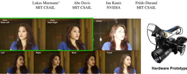
Figure 1: Direct flash lighting creates flat and harsh portraits (top right). Advanced photographers use bounce flash to create a virtual light source that is bigger and comes from a more interesting direction. However, bounce flash is difficult to use. Standard, recommended flash directions (bottom row) are often sub-optimal, and can be difficult to apply in dynamic scenes, even for advanced photographers. We automate the process of using bounce flash by using a motor and sensors to automatically direct the flash toward good bounce surfaces (top left, in green box). Our system makes bounce flash accessible to casual photographers, and frees advanced photographers to focus their attention on other aspects of a shot.
Abstract
Portraits taken with direct flash look harsh and unflattering because the light source comes from a small set of angles very close to the camera. Advanced photographers address this problem by us-ing bounce flash, a technique where the flash is directed towards other surfaces in the room, creating a larger, virtual light source that can be cast from different directions to provide better shad-ing variation for 3D modelshad-ing. However, findshad-ing the right direction to point a bounce flash requires skill and careful consideration of the available surfaces and subject configuration. Inspired by the impact of automation for exposure, focus and flash metering, we automate control of the flash direction for bounce illumination. We first identify criteria for evaluating flash directions, based on estab-lished photography literature, and relate these criteria to the color and geometry of a scene. We augment a camera with servomo-tors to rotate the flash head, and additional sensors (a fisheye and 3D sensors) to gather information about potential bounce surfaces. We present a simple numerical optimization criterion that finds di-rections for the flash that consistently yield compelling illumination and demonstrate the effectiveness of our various criteria in common photographic configurations.
Keywords: Computational Photography, Computational Illumi-nation
Concepts: •Computing methodologies → Computer graphics; Computational photography;
∗e-mail:[email protected]
c
2016 Copyright held by the owner/author(s).
1
Introduction
It is well known among photographers that direct camera flash leads to unflattering images – putting such a small light source so close to the camera prevents soft shadowing, making subjects appear flat and harsh [Burian and Caputo 2003; Northrup 2011; Gockel 2015; van Niekerk 2013; van Niekerk 2015]. Advanced photographers avoid this by using a bounce flash to reflect light off other sur-faces around their subject, thereby creating a much larger virtual light source that can be cast from better directions. Effective use of a bounce flash is difficult though; the photographer must dy-namically predict how light will interact with a complex 3D envi-ronment, considering factors like the color and albedo of a bounce surface, its position and angle relative to the flash and subject, as well as whether the resulting light will create unpleasant shadows. Even savvy photographers often have trouble using a bounce flash. For example, one common mistake is to use the ceiling between the camera and a human subject as a bounce surface [Burian and Caputo 2003; Northrup 2011]. This unfortunately causes the sub-ject’s brow to cast shadows into the eyes, resulting in what is known as ”racoon eyes” [van Niekerk 2015]. Most photography occurs in dynamic situations where both the photographer and subject move through the scene, challenging even seasoned photographers to con-stantly evaluate and manually adjust the direction of their flash to adapt to the new arrangements of camera, subject, and scene. This is so challenging that it is common practice for professional wed-ding photographers to scout location before an event and test out potential bounce surfaces [van Niekerk 2015].
Inspired by the dramatic impact of tools like autofocus, automatic exposure, and through-the-lens flash metering [Jacobson et al. 2000], we propose an automatic solution for controlling the direc-tion of a bounce flash. We augment a regular camera with addidirec-tional
SA ’16 Technical Papers, December 05-08, 2016, Macao ISBN: 978-1-4503-4514-9/16/12
DOI: http://dx.doi.org/10.1145/2980179.2980219
ACM Trans. Graph., Vol. 35, No. 6, Article 190, Publication Date: November 2016
This work is licensed under a Creative Commons Attribution International 4.0 License.
sensors to evaluate the color and geometry of a scene, and automati-cally direct an actuated, camera-mounted flash toward good bounce surfaces. For amateur photographers this provides a way to reap the benefits of a well-placed bounce flash without having to under-stand the principles behind its use. For professionals, we provide a convenient and effective default option for when the photographer wants to focus their attention on other aspects of a shot.
Lighting for photography is a deep topic, and different photographic styles call for different lighting strategies in different situations. We focus primarily on indoor portraiture, the most common use case for bounce flash, and design an objective for evaluating flash di-rections based on documented principles and rules of thumb from established literature on photography. While the ’best’ flash direc-tion in a scene may be a matter of taste, there is often consensus on directions that should be considered ’bad’. Our objective is de-signed to prioritize avoiding these ’bad’ directions and maximize the chances that the user will capture a useful image.
This paper makes the following contributions:
• We present the first solution to automatic bounce flash, us-ing servos to actuate the flash and additional sensors to gather information about the environment.
• We present heuristic criteria to optimize the direction of the bounce flash and in particular maximize the size of the virtual light source, its direction, and avoid color casts. We demon-strate that factors such as scene reflectance, 3D geometry, and subject head direction are critical.
• We evaluate our system’s results in a user study, and explore additional uses in object and panorama photography.
2
Related Work
We review related work on computational illumination and auto-matic metering, as well as guiding principles for bounce flash from the photography literature.
2.1 Flash and Metering
On-Camera Metering Our work is inspired by on-camera meter-ing for exposure, focus, and white balance, which started to appear on cameras in the second half of the twentieth century, e.g., [Jacob-son et al. 2000]. Earlier cameras offered only manual controls. and the introduction of on-camera metering led to metering “modes,” which optimized some subset of the camera’s parameters accord-ing to the current sensor readaccord-ings. Aperture priority mode, for ex-ample, let the user fix the aperture size and automatically adjusted shutter speed and ISO according sensor readings. Today, most cam-eras offer a variety of modes in addition fully automatic metering. Offering several options addresses the fact that there is no one-size-fits-all solution to metering; the “right” settings may be different for different photographers with different goals.
TTL Flash Metering Metering for flash is more difficult than for exposure or focus because the camera has no way to predict the effect of a flash until it is fired. Modern flash metering is called through the lens(TTL) metering and derives from OTF (Off-The-Film) metering introduced by Olympus in the seventies [Jacobson et al. 2000]. It uses a combination of a pre-flash and tight feedback to stop the flash when an image has reached a specified level of exposure. TTL metering is complementary to our work since it only controls the quantity of light, while we aim to control the quality of light, and in particular its size and direction.
2.2 Computational Illumination
Computational illumination is an area of computational photog-raphy that seeks to computationally control and exploit illumina-tion. Like us, several papers have focused specifically on address-ing problems associated with direct flash. However, previous ap-proaches have accomplished this by combining multiple exposures, typically taken with and without a direct flash [Petschnigg et al. 2004; Eisemann and Durand 2004; Agrawal et al. 2005]. More recent approaches avoid firing a visible flash directly at portraiture subjects by instead using near-infrared or UV flashes [Krishnan and Fergus 2009; Zhuo et al. 2010]. Adelsberger et al. [2008] replace the flash with a video projector to finely control the spatial light dis-tribution, but still in a configuration where illumination comes from the camera direction. Like us, they use 3D sensing to adapt the il-lumination to the scene. Raskar et al. [2004] use multiple flashes to extract scene edges and create non-photorealistic renditions. In contrast to these approaches, our work focuses on automating the existing, single-exposure solution preferred by photographers – a bounce flash.
Other approaches rely on additional light sources that are not attached to the camera. For example, the light stages of De-bevec et al. capture spherical basis functions, e.g. [DeDe-bevec 2012] that can be used to computationally relight subjects after the fact. Mohan et al. [2007] seek to achieve similar results with a table-top configuration, and Malzbender et al. [2001] capture relightable textures from multiple viewpoints. De Decker et al. [2009] and Fyffe et al. [2011] added color multiplexing for efficient cap-ture. Boyadzhiev et al. [2013] focus on organizing and recom-bining photos taken of a static scene under different illuminations. Srikanth et al. [2014] mount a light source on UAV, which they direct to achieve rim lighting of a subject. These systems achieve impressive results, but lack the convenience of an on-camera solu-tion. In contrast, we provide a solution that simply augments a form factor photographers are already comfortable with.
The flash has also been used to extract additional information such as alpha mattes [Sun et al. 2006; Sun et al. 2007]. Projector-camera setups can be used to separate different illumination components, e.g., [Nayar et al. 2006], increase depth separation [Levoy et al. 2004] and create photographic effects such as highlighted depth of field [Kim et al. 2011]. Tight synchronization between a projector and the camera readout can further increase the light efficiency of computational illumination [O’Toole et al. 2015].
Photography lighting can also be modified as a post-process using a variety of relighting techniques, e.g. [Wang et al. 2009; Nishino and Nayar 2004], but they can be more involved and robustness is not guaranteed. In contrast, we want to achieve good lighting in cameraby controlling the flash.
2.3 Guidelines for Bounce Flash
In photography, light is usually characterized by three qualities [Hunter et al. 2007; van Niekerk 2013] – 1) Size: a large light source that casts light from many angles will create softer shad-ows and highlights than a small point light source, 2) Direction: the angle of a light source determines where shadows are cast, and how large they are, and 3) Color: a colored light source may cause the subject to appear a different color.
Size and direction are the main challenges for flash photography. Direct flash is by nature too small, which yields harsh shadows and highlights. It also comes from the same location as the camera, casting few shadows that can provide indications of shape. Bounce flash addresses these shortcomings by using indirect illumination to create a larger virtual light source elsewhere in the scene. Effective
use of the bounce flash amounts to predicting the size, direction and color of this virtual light source. We take each of these factors in turn and examine what aspects of the shooting configuration affect them. This discussion informs the sensors we attach to our camera, and how we can define an objective that turns photographic guide-lines into numerical criteria.
Size: The virtual size of the light source as seen from the subject depends on the field of view of the flash and the relative geometry of flash, reflector, and subject. Our prototype uses a flash with a fixed field of view, though flash zoom would be simple to add as a variable to our optimization. The relative distance and orientation of the reflector with respect to the flash and subject then determine the virtual light size. For example, when the flash is projected to-wards a wall that is very close, the resulting light is small. This criterion requires knowledge of the 3D environment, which is why we augment the camera with 3D sensors. Given 3D data, we use a simple computer graphics simulation to estimate the size of the virtual light source.
Direction:Light direction tends to offer the most creative freedom, with a variety of strategies leading to different portrait styles. In the spirit of automation, we seek a solution that most users will find pleasing based on established guidelines outlined in photogra-phy textbooks (e.g. [Gockel 2015; van Niekerk 2013; van Niekerk 2015]). First, most texts agree that the eyes are the focal point of portrait photography and, with the exception of a few styles (such as film noir), they urge photographers to make sure the eye sockets are well lit. This is why the na¨ıve bounce flash approach of direct-ing the flash towards the ceildirect-ing is usually ill-advised; it causes the eyebrows to cast a shadow in the eye sockets. Instead, light should ideally come from just slightly above eye level, since most natural light is above the horizon. When the head is turned to a side, light-ing can then be classified into two main strategies: “broad lightlight-ing”, where light comes from the side facing the camera, and “short light-ing,” where light is cast from the direction the subject is facing. As broad lighting is known to offer weaker shape perception of the face [Gockel 2015; van Niekerk 2013; van Niekerk 2015], we focus on the more common “short lighting” style. In summary, we preferen-tially choose flash directions that result in the commonly accepted style of lighting that places the light slightly above eye level (but not too much), and has a slight bias to the side of a subject’s gaze. This bias requires knowledge of face pose, which we obtain with a face and gaze detector [Baltruˇsaitis et al. 2016].
Color:Finally, photographers are advised to avoid excessively col-orful bounce surfaces that may yield an unpleasant color cast. This criteria is the simplest to understand and implement: our flash should prefer white and gray surfaces to highly saturated ones. Our task is to define and evaluate an objective for controlling the flash direction based on the above principles. For this we need to capture information about the color and geometry of the scene. We do this by augmenting our camera with additional sensors, namely a fish eye camera and 3D sensors. Our objective is evaluated on the data provided by these sensors, and used to computationally control a motor-actuated electronic flash head mounted on our camera.
3
Bounce Flash Objective
As the photographer moves through the scene, our system contin-ually captures the color and geometry of the scene as well as the subject gaze and evaluates potential flash directions. For each can-didate flash direction ®ωc, we use simple single-bounce computer
graphics to evaluate light at the subject location and compute a score S( ®ωc). Every frame, the system finds the flash direction ˆωflash
that maximizes the score S: ˆ
ωflash= arg max S( ®ωc) (1)
As previously outlined, S should favor directions that lead to a bounce flash with good size, direction, and color. For each can-didate flash direction ®ωc, we project the flash frustum onto our
ac-quired geometry to create a virtual bounce light source and rasterize it into an environment map from the viewpoint of the subject, us-ing shadow maps to handle visibility. Then, for each environment map direction ®ωi, we score its contribution and take the integral:
(Note that ®ωi is a direction with respect to the subject, while ®ωcis
a direction with respect to the camera/flash.)
S( ®ωc)=
∫
® ωi
Illumination( ®ωc, ®ωi) · Gaze( ®ωi) · Color( ®ωi) d ®ωi (2)
The three factors inside the integral are binary functions. Illumination() measures whether a point on the bounce surface is illuminated by the flash. To achieve a high objective score, Illumination() must covers a large area of solid angle, which ful-fills the first criterion in Section 2.3. Gaze() favors points in the direction where the subject is looking. The goal of this function is to achieve good modeling while avoiding distracting shadows (sec-ond criterion in Section 2.3). It is non-zero only for points within a vertical range from horizontal to 40 degrees up to avoid eye shad-ows, and extends horizontally by 60 degrees in both directions from the estimated gaze angle.Color() measures the color saturation of the bounce surface and penalizes excessively colorful points (third criterion in Section 2.3). The function is implemented as a thresh-old on wall color saturation, where saturation is calculated from the RGB color channels as
sat = (maxrgb - minrgb) / (maxrgb + eps) . We typically set the saturation threshold to 0.4.
We implement the optimization of Eq. 1 by sampling 89 candidate directions ®ωcuniformly over the hemisphere. The objective
func-tion S( ®ωc) is evaluated by integrating over a cube map rendered
from the position of the subject, where ®ωi indicates a direction
through a texel in the cube map. The system computes the max-imizerωˆflashat interactive frame rates (10 frames per second on a
laptop computer), allowing the prototype to adjust dynamically to changes in subject pose and scene.
Analysis of Illumination(), Gaze(), and Color() Factors Fig-ure 2 shows an example of the factors in the objective function. The results were taken in a mostly white room with reflecting walls to the left, right, and top of the subject. The scene contains am-ple neutral-colored reflectors. Thus, the subject’s gaze direction becomes the deciding factor in determining the light source place-ment.
In the example on the left of Fig 2, the subject looks to the right of the camera. As a result, surface points to the right and back of the camera are considered to be in front of the subject, and contribute to the objective function when illuminated. The optimization proce-dure now searches the space of flash directions for biggest neutral-colored virtual light source in front of the subject. In this case, pointing the flash to the right and up maximizes the objective func-tion (left heatmap) and results in the picture shown in the bottom left.
We now consider the case where the subject is looking to the left of the camera. The set of surface points considered to be in front of the
Gaze() Illumination() Color() Gaze() Illumination() Gaze Left Gaze Right
Figure 2: Shown in the center of the top row are the fisheye image and theColor() factor. Since the room contains many white walls, the color factor is set to 1 for most directions over the hemisphere. The top-left figure shows theGaze() factor when the subject looks to the right of the camera. In this case, directions to the back and to the right of the camera correspond to surface points in front of the subject. The flash direction that maximizes the objective function is upwards and to the right (center row, left).
Shown on the right are theGaze() and Illumination() factors when the subject looks to the left of the camera. The flash direction that maximizes the overlap of the three factors points to the left, up, and slightly behind the camera.
subject changes (Fig 2 top-right). The light source placement from the previous case now barely illuminates surface points in front of the subject. Running the optimization procedure again yields a flash direction to the left, up and back. This direction again maximizes the objective function (right heatmap).
4
Prototype
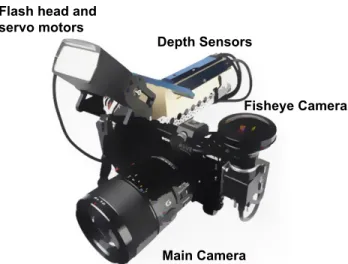
We constructed a prototype based on a Sony a6000 mirrorless cam-era and a Sony HVL-F 43M flash (Figure 3). The flash head was split from the heavier battery pack and mounted on a two degrees of freedom pan-tilt bracket actuated by two high-torque servo motors. The motors are controlled in software by an Arduino-based micro-controller board. Our prototype uses a laptop for computation, but an optimized implementation could perform this computation on the device itself.
The hardware prototype is largely assembled from off-the-shelf parts. These include camera cage, pan-tilt bracket for flash, servo motors, and support structures. Overall, assembly of the prototype does not require advanced knowledge of hardware design or fabri-cation. To facilitate reproducibility, we include a list of parts in the supplementary material. Further, the supplementary material con-tains high-level assembly instructions and schematics for custom parts like the sensor mount.
Geometry Acquisition Our system reconstructs the scene’s ge-ometry using four Intel Realsense R200 active stereo sensors, with a FOV of 56 by 43 degrees. The sensors are aligned to capture a wide field-of-view to the top, side, and back of the photographer. This particular arrangement leaves gaps between the four sensors, and
Depth Sensors
Fisheye Camera Flash head and
servo motors
Main Camera
Figure 3: System overview: Fisheye camera and depth sensors cap-ture data about the camera’s environment. From the main camera feed, we extract the subject’s gaze direction. A laptop computer finds the optimal flash direction and updates the pose of the motor-controlled flash head.
more sensors would be needed to capture a complete hemisphere or more. This would make our prototype unwieldy, and instead we fill in the system’s blind spots by extrapolating the acquired geometry. More details can be found in the appendix. We anticipate spherical or hemispherical depth sensors appearing in the future (driven by the increasing popularity of VR), which will significantly simplify omnidirectional geometry acquisition.
Scene Reflectance In order to determine an appropriate flash direction, we also take the reflectance of the surrounding surfaces into account. Since we only consider flash directions in the upper hemisphere to be relevant for bounce-flash photography, we only need to acquire color images of the upper hemisphere. To this end, we use a180◦fisheye lens mounted on a Pointgrey FL3-U3-88S2C-CUSB3 camera.
Gaze Direction For gaze detection, we capture the camera’s viewfinder feed via HDMI. From the captured video frames, we es-timate subject position and orientation relative to the camera using the Cambridge Face Tracker library [Baltruˇsaitis et al. 2016].
5
Results
The goal of our system is to consistently and automatically pro-vide good indirect illumination. We evaluate this in several ways. First, we have captured various combinations of subjects, scenes, and poses, using the bounce direction chosen by our optimization, as well as standard recommended flash directions for comparison (see Fig. 5). We provide several of these examples for visual com-parison, and also evaluate them in a user study. We also show how our system responds dynamically to changes in a scene. We provide results captured before and after changes in the reflectance, geom-etry, and gaze direction of a scene. In our supplemental video, we show our system responding in realtime to changing scenes, includ-ing one sequence where the system itself moves backwards down a hallway with a walking subject. Finally, we discuss secondary use cases for our system, including object photography and surface tracking for handheld panorama capture.
5.1 Standard Flash Directions
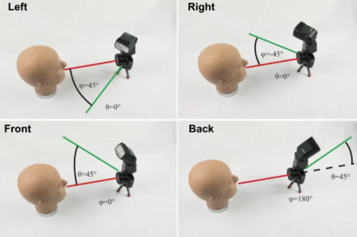
Photography textbooks often introduce the bounce flash by recom-mending some standard directions to point the flash (e.g., [Burian and Caputo 2003; Northrup 2011]). Photographers are taught the strengths and weaknesses of each standard direction, then encour-aged to choose the one that best fits their subject and scene. To evaluate our objective function, we compare images taken using the flash direction chosen by our optimization to some of these commonly recommended, standard directions. Fig. 4 shows the standard directions used for comparison. We captured the stan-dard directions automatically with our system by programmatically moving the flash to each standard direction after capturing the one chosen by our optimization.
φ=45° θ=0° φ=-45° θ=0° φ=180° θ=45° θ=45° φ=0° Left Front Right Back
Figure 4: The standard bounce flash directions we compare against: In the top, the flash is held on eye level, and rotated45◦to the left and right respectively. These directions are meant to achieve short lighting, but often fail depending the environment and subject gaze. On the bottom left, the flash is positioned45◦upwards, to-wards the ceiling. This often produces a neutrally-colored virtual light source, but tends to case unwanted eye shadows. On the bot-tom right, the flash is positioned45◦upwards behind the photogra-pher. This tends to create a large light source, but casts from an unideal direction and often places the light too far away resulting in underexposure.
The flash direction chosen by our system is often close to one of the standard directions. Intuitively, this makes sense, as the standard directions were chosen based on many of the same principles that guide our objective function. However, a given standard direction is not always optimal, and each standard direction has its own failure cases. Our goal is not to always do better than all of the standard directions, but rather to provide an automatic solution that does at least comparably well, avoiding failure cases, making bounce flash accessible to novice users, and freeing advanced users to focus on other aspects of photography.
5.2 User Study
We conducted an online survey to evaluate the performance of our algorithm compared to the directions shown in Fig. 6. The survey is based on 14 indoor portraiture configurations, where each configu-ration is photographed using five different flash directions: {OURS, FRONT, BACK, LEFT, RIGHT}.
We presented each survey participant with all 14 configurations. For each configuration, we presented the participant with a full pair-wise comparison (10 pairs). The order of the configurations and the
order of the pairings were randomized. Participants were asked to chose their preference for all pairs, yielding 140 data points per par-ticipant. We recruited 20 participants for our survey using Amazon Mechanical Turk1; 18 of the 20 participants submitted valid ques-tionnaires.
The scores from these pairwise comparisons are reported in Fig. 7. We test the statistical significance of our results according to the ANOVA framework. The ANOVA confirms that the choice of flash direction leads to significant differences in mean scores at p= 1%. We further conducted Least Significant Difference tests on the scores reported in Fig. 7: With a1% p-value, OURS has a significantly higher mean score than any of the other directions.
5.3 Effect of Geometry, Reflectance, and Gaze
We now look at heat maps representing our energy function in Eq. 1 and see how they are affected by reflectance, geometry, and head di-rection. These visualizations show a color mapping of our objective Sover the space of possible hemispherical flash directions, where green is best and red is poor. Fig. 8 illustrates a scene where geom-etry severely limits options. Most scene surfaces are too distant to yield a good bounce flash, and only a nearby wall is viable. Fig. 9 and 10 illustrate how scene reflectance can yield undesirable color casts and how the color term in Eq. 1 drives the optimization away from such surfaces. Fig. 11 demonstrates the impact of face orien-tation. When this criterion is ignored, the light may come from the direction opposite the subject’s gaze and illuminate only the side of the face closest to the camera. This is often called “broad lighting” and it does not provide good modeling of the face, and it can lead to unpleasant shadows on the other side [van Niekerk 2013; van Niek-erk 2015]. In contrast, our approach takes the head orientation into account biasing our flash direction towards a more pleasant “short lighting” look.
5.4 Moving Subject and Camera
Bounce flash is especially difficult to use in dynamic environments, and yet scenarios that involve a moving camera and subject are very common in photography. Our supplemental video shows our system being used in one such scenario, leading a walking sub-ject down a long corridor. Effective use of a normal bounce flash would be extremely difficult in this scenario, even for expert pho-tographers, as it would involve constantly analyzing the changing surroundings, adjusting the flash, and keeping the camera centered, all while walking backwards in pace with the subject. Fig. 12 shows two of the images captured in this sequence, as well as two screen shots from the accompanying video that illustrate decisions made by our system. This example is best appreciated in the accompany-ing video.
5.5 Additional Applications
Object Photography Photographing objects, in particular shiny objects, can be a surprisingly difficult task for novice photogra-phers. Under ambient illumination, the object appears too dark, and is missing the specular highlights that signal its glossy appear-ance. Adding small light sources like room lights or direct flash introduces very narrow highlights, that don’t fully convey the ob-ject’s shape. A good light setup uses large light sources to model the object’s highlights [Hunter et al. 2007]. However, these light configurations are out of reach for casual photographers.
Fig. 13 shows how our prototype can be used to capture compelling images of glossy objects, without expensive lighting equipment.
(a) Direct Flash
back
right
(b) Static Directions left
front
(c) Our Solution
Figure 5: Direct flash produces harsh illumination. Static flash directions work in some configurations, but do not adjust to subject pose, surface reflectance, or scene geometry. Our prototype takes these factors into account, which leads to consistently good illumination.
ours left
back front right
Figure 6: Our optimized flash direction produces compelling re-sults, which match or exceed the quality of default directions rec-ommended by photogaphy texts.
OURS FRONT BACK LEFT RIGHT
0 5 10 15 20 25 30 35 40
number of wins in pairwise comparisons
N=18 participants p=1%
Figure 7: Each survey participant chose a preference in 140 pair-wise comparisons. Based on a total 2520 individual votes from 18 survey participants, OURS achieves the highest mean number of wins.
For object photography, we disable the gaze detector, and instead instruct the system to place the bounce light on the side of the ob-ject facing the camera. The modified obob-jective function still favors large light sources, which yields pleasing results compared to direct flash or images taken without flash.
ours ours
Wallon the left Wallon the right
Figure 8: In this scene with high ceilings, only a single wall is viable as a bounce surface. In the bottom row, we see the objective function. When we change the direction of the shot, the objective function adapts to the new environment.
Panoramas with Consistent Flash Illumination Another com-mon type of indoor photography is interior photography, especially for real estate, where the goal is to show an entire room in a single picture, often by stitching several smaller photos together [Brown and Lowe 2007]. This poses an additional challenge for bounce flash photography, as a normal bounce flash will change direction as the user rotates their camera. While this may not always be a problem, there are many cases where the bounce flash may start off pointed at a good bounce surface, but rotate toward a poor surface as the user captures images. We use our system to address this by keeping the flash pointed at a consistent surface, specified by the user at the beginning of the panorama. Fig. 13 shows an example where where this prevents pointing the flash in bad directions while
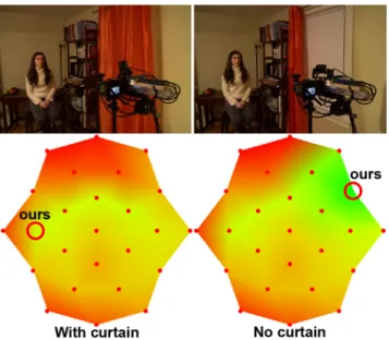
Figure 9: The effect of changing the scene reflectance. On the left, the flash is avoiding the brightly colored curtain, firing at the ceil-ing instead. On the right, the curtain is pulled back, revealceil-ing a white surface. Additional material can be found in the supplemen-tary video.
Reflectance considered Reflectance ignored
Figure 10: In this result, there is a brightly colored curtain ot the front-right of the camera (see Figure 9 and supplementary video). In the left, our solution pointed the flash at the ceiling, leading to an image with natural color temperature. On the right, we ig-nored the measured surface reflectance, assuming white reflectors instead. Ignoring surface reflectance, the system pointed the flash to the bright curtain, which leads to a strong color-cast in the cap-tured image.
capturing a handheld panorama. Video of this feature in use can be found in our supplemental video.
6
Discussion and Limitations
Visual inspection and our user study indicate that our chosen flash directions are preferred in general (see Sec. 5.2). However, there are individual cases where our chosen direction ranked similarly or worse than one of the standard directions. The top of Figure 15 shows one such scenario, where our choice of flash direction is ap-propriate, but provides insufficient flash power, leading to a slightly underexposed subject. In this case, the FRONT and LEFT images show light coming from less desirable directions, but do a better job of exposing the subject. In our survey results, we see that none of the images is a clear winner – some participants placed more importance on direction, choosing our image, while others placed more importance on exposure, choosing the FRONT or LEFT im-ages. The two examples in the bottom row of Fig. 15 show another
Gaze Left Gaze Frontal Gaze Right
ours
Figure 11: Shown in the bottom are the objective functions of the subject looking to the left, straight into the camera, and to the right respectively. Since the photos are captured in a mostly symmetri-cal room, the effect of the gaze tracker is isolated. On the top, we show the detrimental effect of ignoring the gaze tracker, and always assuming frontal gaze instead.
(a)
(b)
(c)
(d)
Figure 12: Corridor Experiment: Our system is rolled backwards down a corridor ahead of a walking subject. (a,b) show images captured by our system during this experiment. In the video, our system is seen responding to different reflectors as it travels down the hall. (c) shows a screen shot just before the flash changes di-rection to avoid a poor reflector on the right wall (highlighted in red). (d) shows a screen shot moments later just before the system changes direction again, this time avoiding a poor reflector on the left (highlighted in red) and pointing at a stretch of white wall about to be revealed behind the previous poor reflector (now highlighted in green) on the right.
common scenario, where our chosen direction is very close to one of the standard directions. In this case, the two choices score very close to each other.
Our estimate of reflectance is na¨ıve and could be improved by in-trinsic image decompositions. However, we found that absolute albedo is not critical when flash output is properly controlled by TTL metering.
The biggest limitation of our current prototype is its form factor. The device must be tethered to a laptop, and the added sensors add significant bulk to the camera. However, we believe that future
iter-direct back front
ours right
no flash left
Figure 13: Our system used to photograph a shiny object: The pic-ture taken without flash is too dark and is dominated by the high-light on the wooden table surface. Pointing the flash left or right does not hit suitable reflectors. Direct flash looks flat and casts a sharp highlight along the front of the object. The picture taken with the BACK direcion also lacks illumination on the foreground object. The FRONT direction yields an acceptable result, but also produces rather sharp highlights and shadows on the objects. Our solution, where the flash was pointed sidewards and up yields soft illumination that accurately conveys the appearance of the espresso cup. Im age 1 Image 2 Image 3 Image 4 Tracks hereOpening
Ours Without Tracking
Figure 14: Handheld Panorama with Surface Tracking: Without tracking (above), the virtual light starts out on a good bounce sur-face, but begins to point through an opening in the wall as the user rotates their camera to capture more images. Notice that the table is underexposed, and a harsh reflection of the bounce flash can be seen in the window. By using our system to track camera movement and keep the flash pointed at the initial bounce surface (below), we achieve better and more consistent lighting across all input images.
ations of the system will be able to fit into the same form factor as most high-end flashes on the market today. The 4 depth sensors and fisheye could be replaced by a single omnidirectional RGBD cam-era (there is no commercial option for this today, but will likely be in the future), the power supply could be shared across the camera, flash, and sensors (the current prototype uses a separate supply for each), and the servo motors are small enough to fit the form factor of current external flashes.
7
Conclusion
Bounce flash can dramatically improve lighting over direct flash, but it has traditionally required skills and work beyond the reach of most photographers. We have introduced the first solution to au-tomatic bounce flash, based on simple objectives inspired by the photography literature to yield a virtual light source that is diffuse and whose direction provides compelling shading and avoids un-desirable shadows. We demonstrated a prototype that uses servos
to orient the flash and additional sensors to estimate the scene in-formation required to estimate our objective function. Our results show that our automatic solution to bounce flash orientation yields portraits that are significantly better not only than direct flash, but also than na¨ıve bounce flash, and that the method can gracefully adapt to changes in configuration.
Acknowledgements
We thank Evan Denmark for his contributions to the gaze detector and want to thank all subjects who appear in the paper and supple-mentary material.
A
Geometry Reconstruction
We take input from our four 3D sensors and perform a combination of filtering and reconstruction to clean up the data and extrapolate it to the parts of the hemisphere they do not cover. As a low-level filter, we apply a four-frame sliding median filter to the depth read-ings. We then use RANSAC and the Manhattan-world assumption for robust geometry fitting of planes to capture walls and ceilings. To the RANSAC plane estimates, we apply a simple IIR filter with weight 0.8 for each new estimate. The missing parts of the field of view, which includes part of the ceiling and the bottom of the walls, is then inferred from the closest planes.
References
ADELSBERGER, R., ZIEGLER, R., LEVOY, M., AND GROSS,
M. H. 2008. Spatially adaptive photographic flash. Tech. rep., ETH, Department of Computer Science.
AGRAWAL, A., RASKAR, R., NAYAR, S. K.,ANDLI, Y. 2005.
Removing photography artifacts using gradient projection and flash-exposure sampling. ACM Transactions on Graphics 24, 3, 828–835.
BALTRUSAITISˇ , T., ROBINSON, P.,ANDMORENCY, L.-P. 2016.
Openface: an open source facial behavior analysis toolkit. In IEEE Winter Conference on Applications of Computer Vision.
BOYADZHIEV, I., PARIS, S.,ANDBALA, K. 2013. User-assisted
image compositing for photographic lighting. ACM Transactions on Graphics 32, 4, 36:1–36:12.
BROWN, M., ANDLOWE, D. G. 2007. Automatic panoramic image stitching using invariant features. Int. J. Comput. Vision 74, 1, 59–73.
BURIAN, P.,ANDCAPUTO, B. 2003. National Geographic
Pho-tography Field Guide: Secrets to Making Great Pictures. Na-tional Geographic.
DEDECKER, B., KAUTZ, J., MERTENS, T., ANDBEKAERT, P.
2009. Capturing multiple illumination conditions using time and color multiplexing. In IEEE Conference on Computer Vision and Pattern Recognition, 2536–2543.
DEBEVEC, P. 2012. The Light Stages and Their Applications to
Photoreal Digital Actors. In SIGGRAPH Asia 2012 Technical Briefs.
EISEMANN, E.,ANDDURAND, F. 2004. Flash photography
en-hancement via intrinsic relighting. ACM Transactions on Graph-ics 23, 3, 673–678.
FYFFE, G., YU, X., ANDDEBEVEC, P. 2011. Single-shot pho-tometric stereo by spectral multiplexing. In IEEE International Conference on Computational Photography, 1–6.
OURS FRONT BACK LEFT RIGHT 0 0.5 1 1.5 2 2.5 3 3.5 4 4.5
OURS FRONT BACK LEFT RIGHT 0 0.5 1 1.5 2 2.5 3 3.5 4 4.5
ours right ours right
ours front back left right
OURS FRONT BACK LEFT RIGHT 0 0.5 1 1.5 2 2.5 3 3.5 4 4.5
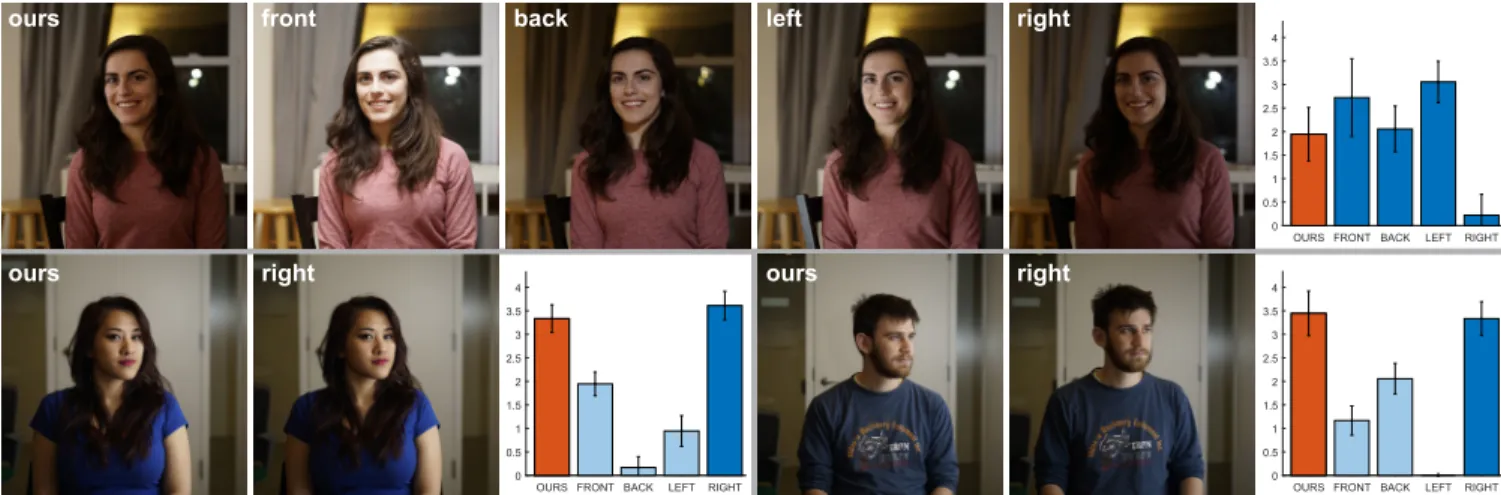
Figure 15: In the scene shown on top, four of the sampled directions score similarly. While the flash direction picked by our system is well-chosen, it is slightly underexposed. Overall, participants preferred the brighter FRONT and LEFT directions.
In other scenes, our chosen flash direction is very close to a standard direction. In the pictures shown in the bottom, OURS matches the RIGHT direction fairly closely. As a result, the captured images look similar, and receive almost equal scores in the survey.
GOCKEL, T. 2015. One Flash!: Great Photography with Just One
Light. Mason Press.
HUNTER, F., BIVER, S.,ANDFUQUA, P. 2007. Light–science &
magic: an introduction to photographic lighting. Elsevier.
JACOBSON, R., RAY, S., ATTRIDGE, G. G.,ANDAXFORD, N.
2000. Manual of Photography. Focal Press.
KIM, J., HORSTMEYER, R., KIM, I.-J.,ANDRASKAR, R. 2011. Highlighted depth-of-field photography: Shining light on focus. ACM Transactions on Graphics 30, 3, 24:1–24:9.
KRISHNAN, D.,ANDFERGUS, R. 2009. Dark flash photography.
ACM Transaction on Graphics 28, 3, 96:1–96:11.
LEVOY, M., CHEN, B., VAISH, V., HOROWITZ, M., MC
-DOWALL, I.,ANDBOLAS, M. 2004. Synthetic aperture
confo-cal imaging. ACM Transactions on Graphics 23, 3, 825–834.
MALZBENDER, T., GELB, D.,ANDWOLTERS, H. 2001.
Poly-nomial texture maps. In Proceedings of the 28th Annual Confer-ence on Computer Graphics and Interactive Techniques, ACM, New York, NY, USA, SIGGRAPH ’01, 519–528.
MOHAN, A., BAILEY, R., WAITE, J., TUMBLIN, J., GRIMM, C.,
ANDBODENHEIMER, B. 2007. Tabletop computed lighting for
practical digital photography. IEEE Transactions on Visualiza-tion and Computer Graphics 13, 4, 652–662.
NAYAR, S. K., KRISHNAN, G., GROSSBERG, M. D., AND
RASKAR, R. 2006. Fast separation of direct and global
compo-nents of a scene using high frequency illumination. ACM Trans-actions on Graphics 25, 3, 935–944.
NISHINO, K.,ANDNAYAR, S. K. 2004. Eyes for relighting. ACM
Transactions on Graphics 23, 3, 704–711.
NORTHRUP, T. 2011. Tony Northrup’s DSLR Book: How to Create
Stunning Digital Photography. Mason Press.
O’TOOLE, M., ACHAR, S., NARASIMHAN, S. G.,ANDKUTU
-LAKOS, K. N. 2015. Homogeneous codes for energy-efficient
illumination and imaging. ACM Transactions on Graphics 34, 4, 35:1–35:13.
PETSCHNIGG, G., SZELISKI, R., AGRAWALA, M., COHEN, M.,
HOPPE, H.,ANDTOYAMA, K. 2004. Digital photography with flash and no-flash image pairs. ACM Transactions on Graphics 23, 3, 664–672.
RASKAR, R., TAN, K.-H., FERIS, R., YU, J., ANDTURK, M.
2004. Non-photorealistic camera: depth edge detection and styl-ized rendering using multi-flash imaging. ACM Transactions on Graphics 23, 3, 679–688.
SRIKANTH, M., BALA, K., ANDDURAND, F. 2014.
Computa-tional rim illumination with aerial robots. In Proceedings of the Workshop on Computational Aesthetics, 57–66.
SUN, J., LI, Y., KANG, S.,ANDSHUM, H. 2006. Flash matting. ACM Transactions on Graphics 25, 3, 772–778.
SUN, J., SUN, J., KANG, S. B., XU, Z.-B., TANG, X., AND
SHUM, H.-Y. 2007. Flash cut: Foreground extraction with flash and no-flash image pairs. In IEEE Conference on Computer Vi-sion and Pattern Recognition.
VANNIEKERK, N. 2013. Direction and Quality of Light: Your Key
to Better Portrait Photography Anywhere. Amherst Media.
VANNIEKERK, N. 2015. On-Camera Flash: Techniques for
Digi-tal Wedding and Portrait Photography. Amherst Media. WANG, Y., ZHANG, L., LIU, Z., HUA, G., WEN, Z., ZHANG,
Z., AND SAMARAS, D. 2009. Face relighting from a
sin-gle image under arbitrary unknown lighting conditions. IEEE Transactions on Pattern Analysis and Machine Intelligence 31, 11, 1968–1984.
ZHUO, S., ZHANG, X., MIAO, X.,ANDSIM, T. 2010. Enhancing low light images using near infrared flash images. IEEE Inter-national Conference on Image Processing, 2537–2540.