by
JAE IN SHIN S.B., SEOUL NATIONAL UNIVERSITY,
February,
SEOUL, KOREA 1965
Submitted in Partial Fulfilment of the Requirement for the Degree of
Nuclear Engineer and
Master of Science in Nuclear Engineering at the
Massachusetts Institute of Technology May, 1975 A/ Signature of Author Department of ... 1... INuclear Engineering May, 1975 ... Thesis Supervisor
Accepted
by
....
*..
.. .. ..
.A . o.. .*00000000000. eSS 000Cairman, Departmental Committee te ~ on Graduate Students ARCVfIV'-. SES21975 IdARt Certified by * v . .
2
CONCEPTUAL DESIGN OF AN HTGR SYSTEM FOR A TOTAL ENERGY APPLICATION
by
JAE IN SHIN
Submitted to the Department of Nuclear Engineering on May, 1975 in Partial Fulfilment of the
Requirements for the degree of Nuclear Engineer
and
Master of Science in Nuclear Engineering
ABSTRACT
A conceptual design for a small HTGR in the 100 MWe size range is described. The reactor drives indirect closed-cycle gas turbine power conversion units using helium as the working fluid and provides both electricity and thermal energy (via a 3800F hot-water utility system) to serve the projected needs of large U.S. Army installations and industrial facilities in the continental U.S. in the post 1985 time frame.
The overall system design combines many of the proven features of the Peachbottom I reactor, the Fort St. Vrain HTGR core, and Oberhausen II turbomachinery. The major unique
feature is the use of an indirect power cycle, with helium-to-helium intermediate heat exchangers.
Cost estimates are summarized which indicate that the ability of the gas turbine cycle to discharge waste heat at a useful temperature gives the HTGR/GT system a significant advantage over nuclear and fossil-fired Rankine systems even though it is inferior to LWR systems on an electric-only
basis. The fossil-fired gas-turbine total-energy concept is identified as its major competitor for the present application.
Thesis Supervisor: Michael J. Driscoll
Associate Professor of Nuclear Engineering Title:
The author wishes to express his deep appreciation to Professor Michael J. Driscoll for his advice and helpful suggestions during this study.
Financial support from the Department of Army, Facilities Engineering Support Agency, under Contract No. DAAK02-74C-0308 is gratefully acknowledged.
The author is indebted to the students whose theses are referenced in this report, to the many students who worked in this area as part of MIT Subject 22.33 "Nuclear Reactor Design" during fall semesters of 1973 and 1974, and to Professors D.D. Lanning and M.W. Golay.
Finally the author is particularly grateful to his wife, Eun-Hee Shin, for her patience and understanding and for her encouragement during this difficult period.
TABLE OF CONTENTS
Abstract 2
Preface and Acknowledgements 3
Table of Contents 4
List of Figures 7
List of Tables 8
Chapter 1. Introduction g
1.1 Foreword 9
1.2 Background and Groundrules 10
1.3 Outline of Report 15
Chapter 2. Discussion of Options 16
2.1 Introduction 16
2.2 General Considerations 16
2.3 Direct vs. Indirect Cycle 21
2.4 Choice of Working Fluids 26
2.5 Applicable Prior Experience 27
2.6 Synopsis and Outline 33
Chapter 3. Power Conversion System 35
3.1 Introduction 35
3.2 Specifications of Design Constraints 35
3.3 Cycle Variations 38
3.3.1 Regeneration 38
3.3.2 Intercooling 39
3.3.3 Combined Cycles 40
3.4 Cycle Optimization 41
3.5 Heat Exchanger Design 45
3.8 Summary 57 Chapter 4. Primary and Auxiliary Systems 59
4.1 Introduction 59
4.2 Primary Coolant System 62
4.3 Major Auxiliary Systems 64
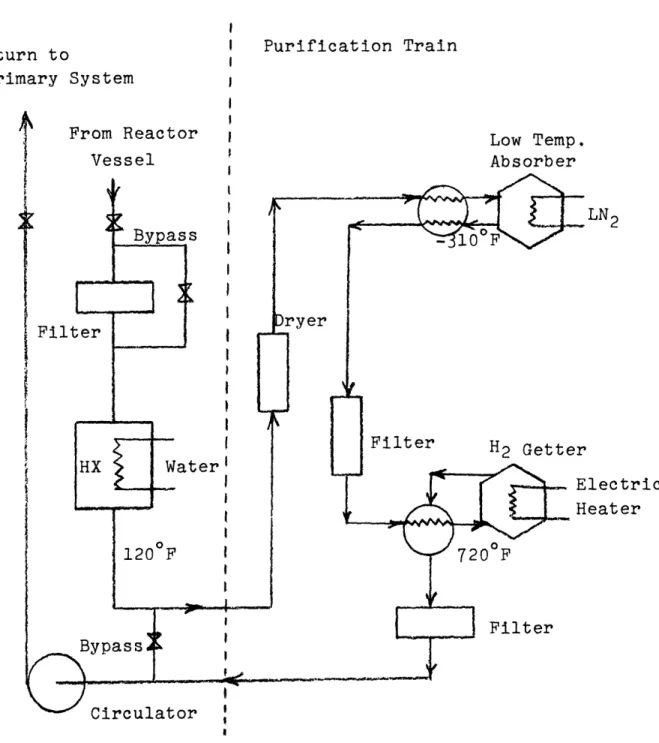
4.3.1 Purification System 64
4.3.2 Shutdown and Emergency Cooling Systems 68
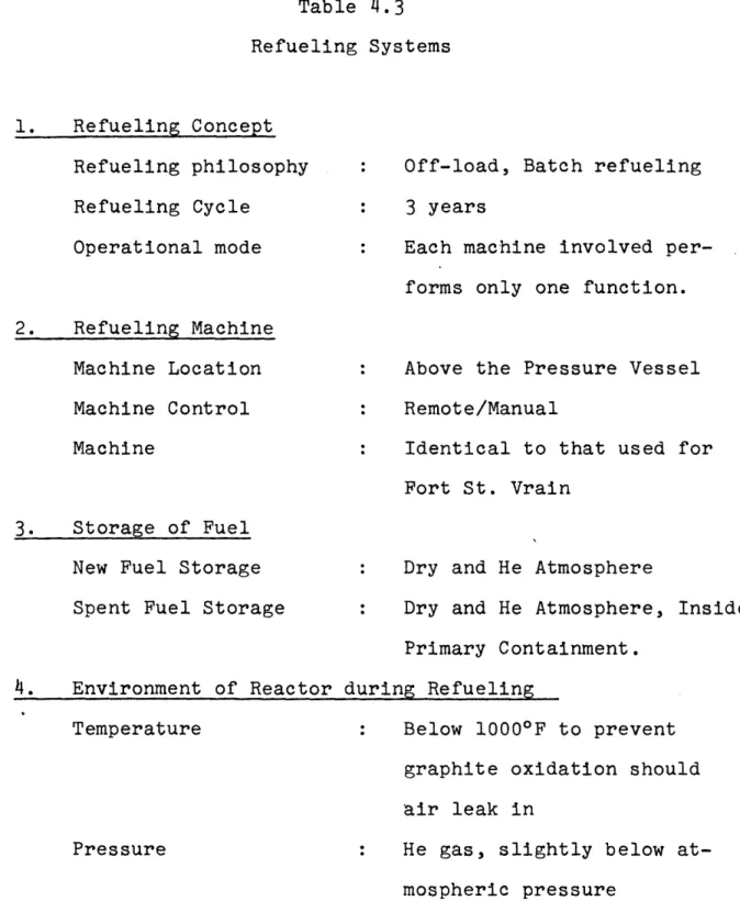
4.3.3 The Refueling Systems 70
4.3.4 Other Systems 72
4.4 Plant Layout 72
4.5 Conclusion 75
Chapter 5. Core Design 80
5.1 Introduction 80
5.2 Design Constraints 82
5.3 Selection of Fuel Cycle 84
5.4 Selection of Fuel Particle Type 86
5.5 Reference Core Design 89
5.6 Discussion and Conclusions 97
Chapter 6. Considerations Related to Safety and Reliability 98
6.1 Introduction 98
6.2 Containment and Associated Systems 100
6.3 Accident Categorization 104
6.4 Primary System Blowdown 107
6.5 Maintainability and Reliability 111
6.5.1 Fission Products 111
6.5.2 Reliability 112
Chapter 7 Economic Evaluation 7.1 Introduction
7.2 Background
7.3 Results of Economic Evaluation 7.4 Discussion
Chapter 8 Summary, Conclusions, and Recommendations 8.1 Introduction
8.2 Summary Description 8.3 Conclusions
8.4 Recommendations
Appendix A Selection of Gaseous Working Fluids A.1 Introduction
A.2 Derivation
A.3 Turbomachinery Design
Appendix B Characteristics of Nuclear Total Energy Systems
B.1 Introduction
B.2 Selection of an HTGR/Brayton Unit over a LWR/Rankine Unit
B.3 Load Tailoring for HTGR/GT Systems B.4 Allocation of Total Energy Costs B.5 Capacity Factor Over Life
Appendix C References 6 115 115 115 117 119 122 122 122 124 126 128 128 129 134 141 141 141 145 148 151 153
Figure Page 2.1 Decision Tree for Specification of System Characteristics 17
2.2 Isometric View of Oberhausen II 32
3.1 Schematic Diagram of Reference Plant 43 3.2 Swiss Federal Institute's Proposed Nuclear Gas Turbine
Regenerator (L1) 50
3.3 General Atomic HTGR/GT Regenerator (G3) 51 3.4 General Atomic HTGR/GT Precooler (G3) 52 3.5 Circuit and Control Schematic of Power Conversion Unit 56
4.1 Primary Coolant System Schematic 63
4.2 Schematic of Purification System 66
4.3 Schematic of Suggested Plant Layout 74
4.4A Vertical Section through the Primary Containment Vessel 76 4.4B Horizontal Section through the Primary Containment Vessel 78
5.1 Fuel Element Design 81
5.2 Horizontal Section through Reference Core Design 92 5.3 Vertical Section through Reference Core Design 93 6.1 HTGR/GT Containment and Associated Systems 102 B.1 Relative Reactor Rating Required to Serve Total Energy
8
LIST OF TABLES
Table Page
1.1 Groundrules 11
2.1 Reactor Ratings Required for Equivalent NTU Service
(100 MWe, 200 MWth ) 19
2.2 Predicted Cost of Total Energy Alternatives in 1974
Dollars 19
2.3 Advantages of Indirect Cycle 22
2.4 Disadvantages of Indirect Cycle 24
2.5 Characteristics of Peachbottom I HTGR 28
2.6 Summary Description of Oberhausen II 30
2.7 Thermodynamic Cycle for Oberhausen II 31
3.1 Input for Cycle Calculation 44
3.2 Cycle State Points 46
3.3 Heat Exchanger Characteristics 48
3.4 Summary of Design Features 58
4.1 Summary Description of Small HTGR Reactors 60 4.2 Main Component Characteristics of Primary Coolant System 65
4.3 Refueling Systems 71
4.4 Auxiliary Systems Checklist 73
5.1 Methods for Increasing HTGR Core Outlet Temperature 83 5.2 Comparison of FSV and HTGR/GT Core Design Parameters 90 5.3 Summary of HTGR/GT Referenced Design Characteristics 91 5.4 Reactivity Control Requirements and Methods for the
HTGR/GT Core 95
6.1 Safety-Related Differences: HTGR/GT vs. Peachbottom I 99 6.2 Factors Affecting the HTGR/GT Blowdown Accident 108
7.1 Groundrules for Economic Studies 116
7.2 Summary of Economic Comparisons (In 1985 $) for Units
Delivering < 100 MWe, 200 MWth 118
Chapter 1 INTRODUCTION
1.1 Foreword
The objective of the work summarized in this report has been to develop and evaluate a conceptual design for a nuclear total utility system (NTUS) for provision of both electricity and thermal energy to large DOD installations in the con-tinental United States in the post-1985 time frame. It has been carried out as part of a program sponsored by the U.S. Army Facilities Engineering Support Agency to determine a strategy for provision of future DOD energy needs in light of recent large increases in fossil-derived energy costs.
The concept developed in this study couples a high-temperature gas-cooled reactor (HTGR) to a closed-cycle gas turbine power conversion system using helium as the working fluid. In many respects the final design may be thought of as an updated and scaled-up version of the Peachbottom-I HTGR combined with Oberhausen-II turbomachinery. It will be shown that a NTUS of this type should be able to deliver energy cheaper than most fossil-fired units or other nuclear options.
In this initial chapter the assumed and derived ground-rules governing the scope of the study will be discussed, and an outline of the body of the report presented.
10
1.2 Background and Groundrules
Previous studies (N1,S4 ) have shown that there are a dozen or more military installations in the continental United States having substantial (>25 MWe) peak electrical demand, which is projected to grow into the 50-100 MWe range in the post-1985 time frame. Thermal energy demand at the same installations averages several times the electrical demand. Two important observations follow:
(a) At and above about 100 MWe small nuclear
plants are potentially competitive with fossil-fired stations (at 1974 fuel costs) even when
operated to produce electric.or thermal power only. (I1,T2)
(b) The installations are well suited to exploitation of the total energy concept, and it is readily demonstrated (Ml) that a system producing both
thermal and electrical energy can deliver the combined products cheaper than a single-product plant.
These circumstances motivated the present investigation. An important part of both the original research proposal and of subsequent work has been the development of an appro-priate set of groundrules governing the study. Table .1 summarizes the final set of conditions, together with com-mentary on the significance of each item. The system
Table 1.1 Groundrules
ITEM
(1) The plant should be licensable under current AEC civilian reactor criteria; and no special provisions will be made for the military nature of the application
(2) The plant should be capable
of assuming entire base elec-trical load at system mid-life and as much of thermal load as shown to be econom-ically practicable.
(3) A specific time frame is designated
COMMENT
(a) Risk to the general public and environmental impact
shall be no greater than a comparable civilian applica-tion, and conform to all applicable governmental regulations.
(b) No site hardening required other than normal seismic resistance; no security beyond civilian norms. (c) The lant should be capable
of being deployed at sites having the general charac-teristics of the larger DOD/ CONUS bases, but no specific bases will be considered at the present time.
(a) Normal capability of IITGR/GT reactor system is approximately
2 MWth/MWe
(b) The electrical load is well defined and already tied in to a centralized distribution system.
(c) Use of heat pumps and absorp-tive air conditioning to
optimize utility load balance is to be evaluated.
(d) Annual total energy growth rate of 3 is assumed; with electrical tending to grow faster than thermal.
(a) 1985 reactor startup is en-visioned; costs will be quoted for 1974 and also escalated to 1985
(b) (c)
A 30 yr. lifetime is assumed. Reliance on state-of-the-art technology is implied; and R&D necessary should be well defined and of limited scope in terms of both financial and time requirements.
12
Table 1.1 (continued) (4) DOD economics will be
employed
(5) Reliance on the local electrical utility grid is restricted.
(6) The stand-alone
capa-bilities of the system are restricted
(a) 10% annual rate used as effective cost of capital. (b) Nuclear fuel carrying charges
are waived; no credit for bred fissile material.
(c) Fabrication, burnup, shipping and reprocessing charges are assessed as in the civilian economy.
(d) No local, state or federal taxes assessed.
(a) Access to grid power provided as required for reactor safety assurance.
(b) It will not be assumed that excess electric power can be sold or given to the grid, but no design features prohibiting this will be adopted.
(c) Access to grid power during scheduled downtime for main-tenance or refueling will be assumed, but not during un-anticipated outages.
(a) On-site cooling tower capa-bility provided for 100% of thermal load
(b) Essential or uninterruptable electrical or thermal loads
(e.g., hospitals) will provide their own emergency power
supplies.
(c) No storage provisions will be made for electric power in the reference design, but feasibility of add-on systems will be
assessed (e.g., H2 production, flywheel storage)
(d) Sufficient thermal (hot water) storage will be provided to smooth the daily load.
In addition, as a result of system reliability analyses it was decided to provide additional assurance against partial system incapacity by providing an on-site fossil-fired total-energy gas turbine unit capable of providing one reactor-loop's worth of energy (50 MWe, 100 MWth). This will insure the following capabilities:
(1) Provision of 100% of rated system power during the estimated 15% of the time when one reactor loop/ turbine plant is out of service.
(2) Provision of 150% of rated system power to meet peak load near the end of plant life -- otherwise it will be necessary to grossly oversize the
nuclear unit.
(3) Provision of all or nearly all power during minimum load conditions: Spring and Fall and weekends, when scheduled inspections, maintenance and refueling operations can be conducted.
(4) Provision of essential services during unscheduled outages.
(5) Provision of the energy reconversion unit for an energy storage system using hydrogen, if such is deemed practicable.
(6) Provision of an added level of emergency power for reactor safety assurance.
14
The many advantages of this back-up system were con-sidered to ustify its modest cost: approximately 150 $/KWe of gas turbine installed or 75 $/KWe of total reactor power.
Finally, the results of this study were to consist of a conceptual design in sufficient detail that it could be used as the basis for discussion of specifics with a reactor vendor and architect-engineer firms, and an economic evaluation of
system costs and the unit costs of power therefrom were to be made and presented in a manner which facilitated comparison with alternatives. In this latter regard, while the focus of the technical effort was to be on the HTGR/GT system, it was recognized that sufficient economic evaluation of
fossil-fired and other nuclear alternatives would have to be carried out to confirm that these systems were less suited to the present application than the HTGR/GT. The magnitude of this phase of the work led to augmentation of the original contract proposal and resulted in a subtask whose efforts culminated in the report: L.J. Metcalfe and M.J. Driscoll, "Economic Assessment of Nuclear and Fossil-Fired Energy Systems for DOD Installations," Feb. 15, 1975. In the present report we will rely heavily upon this document, summarizing rather than repeating its major results and conclusions in the areas noted.
1.3 Outline of Report
The body of this report begins with a discussion of the options involved, and the considerations which support the selection of the HTGR/GT system (Chapter 2). This is followed by a detailed description of the power conversion system
(Chapter 3) and nuclear-related systems (Chapter 4), core-related aspects (Chapter 5), reactor safety (Chapter 6), and economics (Chapter 7). The report concludes with a
discussion and summary (Chapter 8), and appendices containing various details in support of the main text.
16
Chapter 2
DISCUSSION OF OPTIONS
2.1 Introduction
In response to the needs and within the constraints described in Chapter 1, a NTUS concept has been developed around a high temperature gas cooled reactor as the energy source, coupled to a closed cycle gas turbine system as the power conversion unit. Specific design details of the system will be described in Chapter 3. In the present chapter the considerations which led to selection of this particular
combination of characteristics will be documented. Questions such as why not PWR?, and why a Gas Turbine cycle? will be addressed.
2.2 General Considerations
Figure 2.1 is a binary event tree which summarizes the several decisions which had to be made to narrow the choice of system characteristics prior to development of a detailed conceptual design. It is not unique since several different diagrams could have been constructed in which the same (or other) trade-offs were considered in different order. However it does provide a convenient and self-consistent outline
H. CHOICE OF WORKING FLUID
;
0
G. COOLANT COMPATIBILITY
F. COUPLING WITH ENVIRONMENT
E. COUPLING WITH REACTOR
0
H H > O O· >- :E 0 x : E W W[l/) Z lSo D. THERMODYNAMIC CYCLE0
0
C. CHOICE OF ENERGY CONCEPT
B. SELECTION OF HEAT SOURCE
A. DESCRIPTION OF LOAD AND
SPECIFICATION OF GROUNDRULES :E H 1 :V. 0Z H H :3t W ol U
0
U0
C00
HH cn H 00
HE-'0
0
E~ HU3 co0
CUHp
0
E V H H C co ri, W-We Ez
. b18
The initial several issues to be decided: selection of heat source, energy concept and power cycle, can best be dealt with as a package by consideration of the overall interrelation of technical characteristics and economic prospects.
Given the needs defined by the groundrules set forth in Chapter 1, one is led to prefer a high-temperature gas-cooled reactor driving Brayton cycle turbomachinery (the HTGR/GT) based upon the economic advantages stemming from two key technical considerations:
(a) The Brayton cycle can deliver "waste" heat at a temperature useful for hot-water type thermal utility systems, while with Rankine-cycle-based
systems one must divert prime steam for utility use, thereby requiring an inherently larger system
thermal power rating.(see Appendix B)
(b) Since Brayton cycle efficiency can match or surpass that of the Rankine cycle only above about 1400°F turbine inlet temperature, only the HTGR of currently proven reactor types can exploit this advantage.
Table 2.1 compares reactor ratings determined using the power conversion system models of Ref. (M2), which consider use of a HP turbine to extract power to the extent practicable before diverting steam to the utility system heat exchanger. We see that other reactor system ratings must be larger than that of the HTGR/GT. Since both plant capital cost and fuel
Table 2.1
Reactor Ratings Required for Equivalent NTU Service (100 MWe, 200 MWth*) (M2)
System Type HTGR/GT
Thermal Rating (MW)
2814
Fossil-Fired Gas Turbine (FFGT) 313
HTGR/Rankine 358
Fossil-Fired Rankine 383
PWR 550
* peak electrical and thermal loads are not coincident
Table 2.2
Predicted Cost of Total Energy Alternatives in 1974 Dollars (M1) HTGR/GT FFGT PWR/Rankine Electric Energy (mills/KWhr) 14.0 14.2 16.9 Thermal Energy ($/MBTU) 1.43 1.48 1.63 Coal/Rankine Oil/Rankine
Outside Purchase Option (Industrial-user basis)
Basis: 11 $/bbl oil, 30 $/ton coal, 80% plant capacity factor, 10% 30 year plant life
cost of money, 24.6 25.2 2.77 28.0 2.84
20
consumption are roughly proportional to thermal rating, the HTGR/GT has an inherent and overriding economic advantage. Note, however, that this preference follows from the total energy nature of the application -- for an all-electric or all-thermal load the PWR/Rankine and HTGR/GT systems would have comparable thermal ratings, and the PWR would be
pre-ferred in the size range pertinent to military applications. Table 2.2 illustrates the preceding conclusions in a
more specific fashion, in terms of the results of the economic intercomparisons developed and reported in Ref. (Ml). As
can be seen, the fossil-fired gas-turbine (FFGT) is the most serious challenger to the HTGR/GT as the preferred system.
The various pro's and con's of this alternative and appropriate recommendations for future investigations of this concept are spelled out in Ref. (M1). In the present instance we will
focus on the HTGR/GT system exclusively, the preferable nuclear alternative.
A final point to be noted is that the PWR, while less attractive than the HTGR/GT in the present application, is not disqualified by a prohibitive margin. However this system has been more thoroughly analyzed in recent studies by ORNL
(K1) NUS (N3) and the IAEA (Il), which again motivates our exclusive preoccupation with the HTGR/GT in the present evaluation.
2.3 Direct vs. Indirect Cycle
Considerable attention was devoted to determining whether a direct or indirect cycle should be employed. Tables 2.3 and 2.4 summarize the spectrum of considerations which led to the final decision to adopt the indirect cycle. The over-riding factor proved to be the greater assurance of maintain-ability/reliability for the indirect cycle -- particularly important where a single reactor system is responsible for the bulk of both the electric and thermal requirements for a given installation.
Calculations of fission product release and plateout indicated that contact doses of on the order of 20 Rem/hr could be experienced on direct cycle turbomachinery unless ultra-high core integrity were achieved. Since neither the capability for decontamination under in-service conditions nor its lack of detrimental metallurgical effects over plant life has yet been demonstrated and since it was considered important to employ state-of-the-art design in an area as vital (and as expensive to research) as core and fuel element design, the use of the indirect cycle was considered to be sufficiently attrac-tive for the present application. Some thought was given to full-flow filtration, and while found to be marginally feasible from a technical standpoint, it represents only a partial
solution to the problem because radioactive noble gases can traverse the filter and contaminate the primary loop with their daughter products.
22
Table 2.3
Advantages of Indirect Cycle
1. Ease of maintenance; no need for on-site decontamination facility.
2. Better protection of reactor core during normal and acci-dent conditions.
3. Prototype experience available for all constituent components and systems.
4. Smaller containment is practicable.
(a) Except perhaps for tritium the turbine plant will be uncontaminated and also outside the containment. (b) Machinery accessible with
reactor at power; less compact arrangement is practicable (a) Core is not pressure-cycled
during use of helium inven-tory control.
(b) Turbine plant accidents (e.g., blade ejection) do not rupture and depressurize primary
system.
(c) Precooler leaks can not intro-duce water into primary system. (d) Turbine bearing lubrication
and shaft-seal problems do not affect primary coolant. (a) Oberhausen II, a 50 MIWIe
fossil-fired helium-Brayton system, will be on line in 1975.
(b) Location of turbine plant out-side containment favors use of familiar horizontal turbo-machinery.
(c) Primary circuit similar to Peachbottom, Dragon, other gas-cooled reactors.
(a) Power conversion equipment located outside containment. (b) Higher post-accident ambient
pressure improves heat removal. (c) Can help hold down capital
Table 2.3 (continued)
5. Provides a more flexible overall system design
6. Potentially simpler reactor system control.
7. Less expensive turbomachinery and associated plant.
8. Switch to direct cycle in second generation plants is probably feasible.
9. Permits use of hydrogen-cooled generators
10. Compatible with supplementary or alternative fossil-firing: the same power conversion system design can be used in both nuclear and fossil
in-stallations; it may be possible to install fossil-fired HXer in parallel with the reactor 1HX (see Ref. U1)
(a) Steam generator can be sub-stituted for intermediate HX unit where large steam demand occurs (e.g., industrial fac-ility).
(b) It may eventually be possible to substitute chemical reaction units for HX units to produce
synthetic fuel.
(c) Primary coolant and turbine plant coolant chemistry can be individually optimized. (d) Easier to substitute more
ad-vanced power plant cycles later: add intercooling or bottoming cycle.
(a) Turbine plant transients iso-lated from core, or their effect dampened.
(b) Isolates other loops from transients in one loop. (a) Entire system need not be
built to nuclear standards. (b) Eliminates need for
inter-mediate loop between pre-cooler and utility system.
(a) For example: adopt Shipping-port-type multiple-vessel containment.
(a) No need to put hydrogen system inside containment. (a) One can use either nuclear
or fossil heat, or both: Oberhausen II is a fossil-fired TE system.
(b) Some European closed GT
systems burn pulverized coal-a fossil coal-alterncoal-ative of inter-est to DOD; but essentially any fuel can be accommodated. (c) May offer an economic approach
to providing backup power during nuclear unit outages, or extra power during peak demand.
24
Table 2.4
Disadvantages of Indirect Cycle
ITEM COMMENT
1. Slightly lower cycle
efficiency. (About 3%
less than GA or European
large direct cycle HTGR/GT designs)
2. Requires expensive inter-mediate heat exchangers.
3. Departs from mainstream of currently active
reactor-oriented GT system development
(a) Turbine inlet temperature about 75°F lower than direct cycle; temperature loss
across thelHX is slightly greater than that lost in
the added intermediate loop
in the direct cycle, but for
every 200F loss at the
turbine inlet the cycle loses 0.5% efficiency whereas per 200F increase at the compressor
inlet the cycle loses 1.5%. (b) Primary circulators consume about 7 MWe of electric out-put (equivalent in effect to another 100°F core outlet AT). (c) Forces consideration of
in-creased core outlet tempera-ture,greater reliance on absorptive air conditioning. (a) Design studies indicate
that high performance design is possible at reasonable cost. (b) Development program is
straight--forward and success assured if derating of operating tempera-ture is a permissible fall-back position.
(a) Most of this development, par-ticularly that by General Atomic, is for much larger systems:
250 TMWe/loop.
(b) Reactor core and most auxiliary system designs are not strongly affected.
Table 2.4 (continued)
4. Rules out use of PCRV
5. Constrains system design pres-sures: to insure against radio-active contamination of turbine plant its pressure should exceed
that of reactor system.
6. Complicates helium handling and purification system design.
(a) Places strong emphasis on pro-tection against loss of coolant accident.
(a) Peachbottom primary pressure (305 psig) is less than
Oberhausen II turbine plant pressure (410 psig); but later
HITGR's are higher (710 psig). (b) If inventory control is used
turbine plant pressure will be decreased during part-load operation.
(a) Must isolate (hence duplicate) turbine plant helium systems to prevent cross-contamination.
26
2.4 Choice of Working Fluids
The final two branches in Fig. 2.1 relate to the choice of working fluid in the primary and secondary systems. Here there is little room for debate as helium is the coolant of choice in all recent industrial applications of high tempera-ture reactor technology. Extensive British experience with
CO2 appears to put the upper limit on useful operating tempera-tures with that fluid at about 12000F -- too low to permit its use in gas turbine power cycles. Other non-inert gases react even more strongly with graphite or structural metals at the
high temperatures of interest. Appendix A outlines a theoretical treatment which shows in a concise manner the superiority of
helium to other inert (and non-inert) gases with respect to heat transfer and transport capabilities and as the working fluid in thermodynamic cycles.
If helium is used in both the reactor and turbine plants, then quite naturally both cycles are closed. A system in which a helium primary circuit was used to drive open cycle (air) Brayton turbomachinery has been investigated and found to offer no worthwhile advantages (U1). Thus we were led to select a helium/helium arrangement. This had the added advantage that the secondary system pressure could be kept higher than the primary system pressure, assuring in- rather than out-leakage and thereby providing greater assurance against release of radioactivity.
2.5 Applicable Prior Experience
Given the decision to employ an indirect cycle, several other system characteristics follow immediately, leading to specification of a plant having a strong resemblance in its various parts to three well-known prototypes: the Peachbottom I Reactor, fueled by a Fort St. Vrain type core, driving
Oberhausen II turbomachinery. All of these systems in turn have been evolved from many years of related experience which we will not attempt to review here.
Use of the indirect cycle all but precludes economic application of the integral primary system concept because of the large physical size of gas-to-gas heat exchangers.
(De-signers of large direct-cycle HTGR/GT plants have also found it difficult to cram the entire primary system into a non-oversized reactor vessel). Therefore the principal advantage
of using a prestressed concrete reactor vessel (PCRV), as in the large central station HTGR designs, is removed. Moreover, the plant size under discussion is still small enough to permit
use of a shop-fabricated steel pressure vessel which can be transported to the site. Pursuit of this line of reasoning to its logical conclusion leads to a general reactor system design resembling that of the Peachbottom I Reactor, whose major
characteristics are summarized in Table 2.5. In the seven years of operation prior to its recent decommissioning this
28 Table 2.5 Characteristics of Peachbottom I HTGR* 40 MWe; 115.5 MWth Net Efficiency: Coolant: 34.6% (Rankine cycle)
Helium, outlet temperature = 13420F; 350 psia, Flow rate = 446,900 lb/hr
Moderator: Graphite
Fuel: U(93% enriched) and Th carbide dispersed
in graphite Refueling schedule:
Primary circuit:
Reactor Pressure Vessel: Containment:
Owner/Operator: Designer:
Start of construction: Reactor Critical:
Full Power Operation: Final Shutdown:
Lifetime Forced Outage Rate: Capital Investment:
batch, 3 year cycle, off-load refueling 2 loops each containing one blower and one steam generator
14 ft I.D. x 35.5 ft overall height ASTM A212 grade B carbon steel.
Cylindrical steel shell, 100 ft dia., 162 ft overall height
Philadelphia Electric Co. General Atomic February 1962 March 1966 May 1967 November 1974 = 5.4% (from Ref. N2) $28.1 x 10⁶ (= $703/kw) 17.0 x 10 R&D $45.1 x 10⁶ Total
*Except where otherwise indicated, data from Ref. (D2)
reactor performed in an exceptionally reliable manner, testifying to the basic soundness of its various design features.
The power conversion unit must inevitably have many
features in common with the Oberhausen II plant in Germany --a 50 MWe fossil-fired turbine pl--ant. This system h--as been designed to simulate a 300 MWe unit for subsequent service with large HTGR's. Thus in the present application some refinement in design to reduce size is possible; this will also permit packaging the unit as a single transportable module. Table 2.6 summarizes the characteristics of
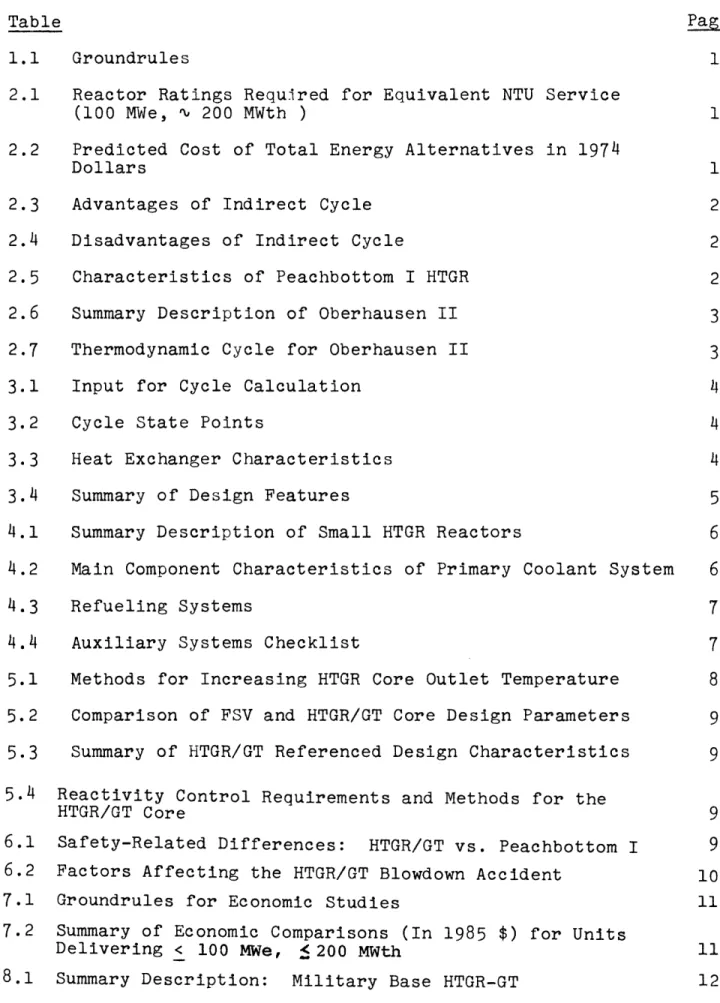
Oberhausen II, which is currently undergoing commissioning exercises prior to operation as part of a total energy system. Fig. 2.2 shows an isometric view of the unit.
Another point to note is that even the most unique feature of the present concept -- the intermediate heat exchangers, in which we propose to use Incoloy tubing --has precedent applications already in being:
(a) The fossil-fired Oberhausen gas heater uses Incoloy tubing at a temperature and differential pressure
close to those of present interest, and in a more corrosive atmosphere on the fire-side.
(b) Incoloy is currently specified for the superheater region of steam generators in large HTGR's at a pressure much higher than the present application,
30
Table 2.6
Summary Description of Oberhausen II
1. System Characteristics. Plant capacity:
Type of cycle: Heat source: Working fluid:
Helium mass flow rate: Pressure losses: Control methods: Thermal efficiency: 2. System Components. Turbomachinery HP compressor; LP compressor; HP turbine: LP turbine; Recuperator: Precoolers (2): Intercoolers (2): Helium heater:
50 MWe (net) plus 53.5 MW heat*
Indirect, regenerative, one stage of intercooling.
Fossil fired heater, coke oven gas. Helium
187 lb/sec. 10.4%
He inventory, compressor bypass 32.6% gross, 31.3%** net
Two shaft/reduction gear coupled, oil lubricated-Labyrinth shaft seals. 5500 rpm, 15 stages, blade
length-2.83 inches (inlet) 2.1 inches (outlet) 5500 rpm, 10 stages, blade
length-4.06 inches (inlet) 3.35 inches (outlet) 5500 rpm, 7 stages, blade
length-5.9 inches (inlet) 7.87 inches (outlet) 3000 rpm, 11 stages, blade
length-7.87 inches (inlet) 9.84 inches (outlet) Tube bundle cross counter flow, 17500 tubes, 0.47 inches O.D., 0.04 inches thickness, 73.8 ft total length, 14.8 ft shell dia., lx105 sq. ft surface area, 87% effectiveness, 130 MWth duty. Externally finned tube, 11800 ft2 total
surface area per unit
Externally finned tube, 42000 ft2 total
surface area per unit.
Sulzer hot gas generator plus Ljungstr6m air heater, Incoloy 807 tubing, 92.2%
efficiency, 57.4 ft length, 41 ft ft height, max. tube wall temp. 14720F.
utility delivery temp. 2300F, utility return temp. 104°F
based on total fossil energy supplied.
33.94% efficiency based on heat transferred. Data from Refs. (B2,B3,B4, )
Table 2.7 Thermodynamic Cycle for Oberhausen II Inlet O Inlet Temp.( F) Press.(psia) a. LP Compressor b. Intercooler c. HP Compressor d. Recuperator (cold) (hot) e. Fossil-Fired Heater f. HP Turbine g. LP Turbine hl. Precooler(heating part) h2. Precooler(cooling part) 77 181 77 257 860 783 1382 1076 336 113 152 224 223 416 156 408 391 239 154 153 i. Gear
32 f e d r I1 ! a. LP Compressor b. HP Compressor c. HP Turbine d. Gear e. LP Turbine f. Generator g. Precooler (2) h. Intercooler (2) i. Recuperator
k. Concentric Double Duct
at a slightly lower temperature and in a more corrosive environment on the steam side.
(c) Some of the newer PWR designs use Incoloy steam
generators, at much higher pressure but considerably lower temperature than required by the HTGR/GT.
In view of these considerations and of the fact that even higher temperature heat exchangers are currently being de-veloped for chemical reaction units to be used with HTGR's, the success of the present design appears assured even
without an extensive R&D program.
Finally, a considerable amount of prototype experience exists in the area of core design, for which we rely heavily upon the Fort St. Vrain Reactor, currently in its start-up test program. Further discussion of this area will be deferred until Chapter 5.
2.6 Synopsis and Outline
In this second chapter we have discussed the con-siderations which led to selection of a reference design concept involving a total energy system centered around a HTGR reactor driving (indirectly, via intermediate heat exchangers) closed cycle gas turbines, using helium as the primary and secondary working fluids. In Fig. 2.1 we
illustrated a binary decision tree for the major points at issue. The primary factors in support of the path shown in
34
the figure can be summarized as follows:
1. Army base energy needs are projected to reach 100 MWe at a number of installations in the post 1985 time frame
-(a) a size where nuclear reactors become competitive with fossil fired systems at current fuel prices, particularly if
(b) total energy systems are used, to take maximum advantage of the high-capital-cost, low-fuel-cost nuclear system by maintaining a high overall
system load factor.
2. The Brayton cycle has an inherent advantage over the Rankine cycle in total energy systems because it can maintain high efficiency while discharging high
temperature "waste" heat.
3. An indirect cycle is selected primarily on the basis of assured maintainability,
4. The turbine plant employs a closed cycle because of the improved overall efficiency and economy possible with such systems.
5. An inert gas working fluid is desirable to permit high operating temperatures without excessive corrosion, and finally
6. helium is preferred because of its overall superior combination of physical properties.
In the next chapter a detailed conceptual design of the HTGR/GT system will be developed.
Chapter 3
POWER CONVERSION SYSTEM
3.1 Introduction
In the previous chapter the concept of a high temperature gas cooled reactor indirectly coupled to a closed cycle gas turbine power conversion unit was identified as a preferred candidate for total energy applications.
In the present chapter the characteristics of the conversion system will be developed in some detail, including establishment of cycle state points, mass flow rates, pressure losses and the cycle energy balance. Several system variations will be con-sidered, including the extent of regeneration and compression intercooling, and a number of key issues related to system performance and economic viability addressed, such as design
of the intermediate heat exchanger, and the use of absorptive air conditioning and/or heat pumps for load tailoring.
3.2 Specification of Design Constraints
There are a number of considerations based upon experience and precedent which establish an envelope within which system optimization can be carried out. The groundrules spelled out in Chapter 1 constitute a further set of constraints. The items enumerated below translate these considerations into specific requirements imposed upon the present design:
36
(a) A mixed mean core outlet temperature of 15000F is established based upon primary system materials performance limitations. The ultimate determinant here appears to be fission product release from the
fuel: an increase in gas exit temperature of 50°F corresponds roughly to a factor of three increase in anticipated primary circuit activity (G2). The value selected is slightly higher than the Fort St. Vrain design value of 1445°F, but less than values
already achieved in practice and pronosed by others for future HTGR designs. Furthermore, since an indirect design has been chosen, the incentive to achieve ultra-low activity levels to facilitate
turbomachinery circuit maintenance has been reduced. (b) Heat sink reliability requirements lead us to specify
a full-capacity on-site mechanical-forced-draft wet cooling tower. A partial-capacity auxiliary heat
sink would be required in any event to permit delivery of rated electric power during periods of low thermal energy demand or thermal utility system outage. The type of cooling tower selected is based upon the lower cost of this type of unit. Because the chemical treat-ment used in the cooling tower water, and the aeration of the water, are not compatible with optimum water treatment of the utility system water, the cooling tower is coupled to the system by a heat exchanger.
Allowing for typical temperature differences in the heat exchangers involved this leads to a practical
value of 1300F for the compressor helium inlet tempera-ture in the power cycle.
(c) Because a hot-water-type utility system exhibits optimal performance for a supply temperature in the vicinity of 3800F we were similarly led to specify a precooler helium inlet temperature of 4800F.
(d) Considerations of reliability -- from both a power provision and a reactor protection point-of-view --led to specification of two primary loops and turbo-generator plants. In this we arrive at a design quite similar to Peachbottom I. It is also convenient in that each loop then matches the Oberhausen II rating
of 50 MWe. There is considerable incentive not to employ more than the minimum number of main loops because of the dominant role of plant capital cost
in determining the economic viability of nuclear units in the small size of present interest.
Given this very general set of constraints it was then possible to proceed directly to consideration of more specific
38
3.3 Cycle Variations
There are many versions of closed cycle gas turbine
systems which could be considered for the present application. Indeed, because we are employing an indirect, non-integral design there is considerably more leeway for variation than in the integral designs proposed for large HTGR/GT systems. The major variations to be discussed here are whether or
not to use regeneration and intercooling. In addition the use of combined gas/steam turbine cycles is discussed.
3.3.1 Regeneration
The use of regenerative heat exchangers between the turbine exhaust and compressor discharge streams is a fundamental design choice. This unit is large and expensive -- about the same
size as the 1HX between the primary and turbine plant systems.
Omitting the regenerator permits higher utility water temperatures, and makes it easier to drive the steam generator of a combined
cycle. However without it the system efficiency is only about
25% and the optimum compression ratio is higher than in a
regenerative cycle -- leading to higher design pressures or larger equipment sizes in the design tradeoff process. All
things considered the use of a regenerator is desirable, as
the penalties associated with its omission were prohibitive. Oberhausen II, for example, also employs regeneration, as do most large HTGR/GT design studies.
3.3.2 Intercooling
The use of intercooling between compressor stages is a well-known approach for achieving high thermodynamic efficiency in the Brayton cycle. In the present application, however,
compression intercooling has a number of disadvantages: (a) In an optimized cycle it results in a higher
com-pression ratio and lower utility water temperature: if de-tuned to mitigate these characteristics one loses the efficiency advantage for which it was in-stalled in the first place.
(b) For optimum performance the coolant water discharge temperature from the intercoolers is sufficiently low that the thermal energy it contains is truly waste heat. Thus we enhance electrical utilization at the expense of thermal utilization.
(c) The intercoolers are moderately expensive and increase system size, complexity and vulnerability to
mal-function.
In view of the above it was decided to omit compression
intercooling. Note that this departs from Oberhausen II practice. 3.3.3 Combined Cycles
Considerable attention has been given of late to combined gas turbine/steam turbine cycles. Open cycle fossil-fired gas
40
bottoming cycle are presently being marketed for utility service. Arrangements suitable for use with closed cycle systems have
been published (B6,M4). General Atomic has studied an isobutane bottoming cycle for use with HTGR/GT systems (S1). We have
rejected these alternatives in the present instance for several reasons:
(a) After a point, high efficiency per se is no longer attractive. In particularin a total energy system with a high thermal demand the steam turbine would only be operated during infrequent peak electrical load situations.
(b) In the present application system reliability con-siderations have led us to require a 50% capacity fossil-fired gas turbine backup unit -- which can also provide peaking service.
(c) Furthermore, within the design envelope established for the present applications the net improvement in system efficiency is quite small: only 38% (steam bottoming cycle) vs. our reference value of 33%; if isobutane cycles are developed, however, it may be possible to achieve efficiencies as high as 48%. (d) Again, the system is complicated, and vulnerable
to malfunction and misoperation.
In making the decision not to utilize a combined cycle we
also considered, but rejected as unneeded, the potential capability of the system to store energy (as hot water or steam) for later conversion to electric power. Load-tailoring, as discussed in Appendix B proved to be more attractive.
Having established both by reference to previous design studies and scoping calculations of the various cycles discussed above that the simple regenerative cycle was preferable we are now prepared to consider specific items related to cycle opti-mization.
3.4 Cycle Optimization
The major task of the work described in this chapter involved determination of the specific state points of the turbine plant thermodynamic cycle. This work was carried out primarily through use of the in-house computer program CYCAL II, an updated and improved version of the program described in
Ref. (H2).
Although pressure has a quite small effect on Brayton cycle performance when a nearly ideal gas such as helium is used, a useful first step was to select system operating pressure. Various factors were taken into account:
(a) Total capital costs are a trade-off between turbine plant cost which decreases as pressure increases (due to reduced size), and reactor vessel cost which increases with pressure. Simple economic models applied to
direct cycle plants typically yield optimum pressures on the order of 800 psi, with a rather broad minimum. (b) It was considered highly desirable to have the turbine
plant pressure exceed that of the primary circuit to provide positive assurance against leakage of radio-activity into the turbine plant. Since inventory
42
control was also considered desirable, it was then necessary to make the pressure differential fairly
substantial. This involved no economic penalty because one can exploit the advantage of decreasing
turbomachinery cost at high pressure and decreasing reactor vessel cost at low pressure, as noted in (a). The limit on the differential pressure was felt to be high temperature creep of the 1HX tube material,
Incoloy 800.
(c) It was considered desirable not to move too far
from proven state-of-the-art technology: Peachbottom I at 305 psig, Fort St. Vrain at 688 psig, Oberhausen at 408 psia.
(d) Moderately low primary system pressures also provide additional assurances against loss of coolant
accidents and decreased likelihood of self-inflicted damage should the event occur.
In view of the above considerations a primary system pressure of 400 psia and a turbine plant pressure of :900 psia were chosen for the reference design.
With the foregoing preliminary points in mind we can pro-ceed to a more detailed evaluation. Figure 3.1 shows the system layout considered and Table 3.1 lists the detailed input required for cycle performance computations: the entries all represent attainable state-of-the-art characterisitcs, some of which
PC
U
CT
C: Compressor
G: Electrical Generator IHX: Intermediate Heat
Exchanger PC: Primary Circulator CT: Cooling Tower H: Reactor PR: Precooler R: Recuperator or Regenerator TU: Turbine U: Utility System
Table 3.1
Input for Cycle Calculation
Desired Electrical Output at Bus: 100 MWe Electric House Load: 3 MWe Pressure Loss Coefficients
Reactor to 1HX: 2.04% 1HX to Circulator: 0.50 Circulator to Reactor: 1.20 1HX to Turbine: 0.026 Turbine to Regenerator: 0.131 Regenerator to Precooler: 0.345 Precooler to Compressor: 0.70 Compressor to Regenerator: 0.30 Min. Precooler Inlet Temp.: 4800F Min. Compressor Inlet Temp.: 130°F Max. Regenerator Effectiveness: 0.87 Isentropic Turbine Efficiency: 0.90 Isentropic Compressor Efficiency: 0.88 Electrical Generator Efficiency: 0.88 Circulator Mechanical Efficiency: 0.99 Turbine Mechanical Efficiency: 0.985 Compressor Mechanical Efficiency: 0.985
represent a preview of design evaluations discussed later --such as for the lHX.
Table 3.2 lists the constrained optimum conditions generated by the computer program. As can be seen a quite respectable
efficiency of approximately 33% is developed at a rather modest
compression ratio of 2.4. Note that use of an indirect cycle
has cost us only 75°F in turbine inlet temperature. This loss is compensated for to some degree by a lower compressor inlet temperature (1300F) -- in a direct cycle an intermediate
coolant loop would have had to be interposed between the utility water system and the turbine plant to prevent con-tamination of the utility water, which would have cost about
40°F added AT.
3.5 Heat Exchanger Design
The major heat exchangers required in the power conversion system (lHX, Regenerator, Precooler) are large and costly com-ponents which contribute in an important way to overall system
cost (110 $/Kw all-together). Their sheer bulk greatly affects plant layout and the complexity of the ductwork, most of which is concentric. Thus an important subtask of the present work involved optimization of their design using available cost function(1M3) (P2) and thermal performance data on heat ex-changers (F2).
46
Table 3.2
Cycle State Points
Inlet Temperature (°F) Inlet Pressure (psi) Outlet Pressure
(psi)
Reactor 1HX (Primary) Circulator lHX (Secondary) TurbineRegenerator (hot side) Precooler
Compressor
Regenerator (cold side) Thermal Efficiency (%) Compression Ratio
Turbine Pressure Ratio Gas Flow Rate (lb sec)
Utility Water Temperature (F) Heat-to-Electric Power Ratio Net Fuel Utilization
953.31 403.33 400.00 1500.00 399.63 396.82 942.79 396.76 403.49 864.66 902.95 900.00 1425.00 900.00 383.12 934.87 383.09 380.23 480.00 380.18 378.83 130.00 378.79 906.30 409.89 906.27 903.00 33.30 2.40 2.35
444 (Primary) - Total (sum of
2 loops)
441 (secondary) - Total (sum of
2 loops)
380 1.8347 0.9247
gas was put inside the tubes in the HX and recuperator to provide greater protection against tube failure and to reduce the shell cost. In addition, in the lHX this meant that
plugging of leaking tubes could be done from the uncontaminated tube side.
Table 3.3 presents the detailed results of the extensive, iterative design study carried out on the heat exchangers in question. It should be noted that while the analytical
optimum pitch-to-diameter ratio was determined to be 1.2, the value of this parameter was set at 1.35 to facilitate the difficult process of welding tubes into such a close-packed matrix.
Of particular interest in Table 3.3 is the cost of the HX units (1. 7 million each), which is felt to be a rather modest price to pay for the advantages they offer. In addition, while one would have to carry out a parallel detailed direct cycle design to be certain, it is felt that this cost and more is recovered elsewhere in the plant because of the lower primary circuit pressure, elimination of intermediate loops on the utility water side, smaller primary containment, etc.. It is also evident that the 1HX is nothing more than a special type of regenerator, distinguished only by its higher service tempera-ture. In view of this latter observation it was not considered necessary to carry the design process further; a number of
48
Table 3.3
Heat Exchanger Characteristics
General:
Type: Shell and Tube Flow: Axial Counterflow Geometry: Square Tube Bundles Specific:
1HX Regenerator Precooler Heat Transfer Area, sq. ft. 59201.0 52001.2 71751.9
Number of Tubes 14699 23542 29164
Length, ft. 35.78 27.66 30.81
Diameter, ft. 6.6 5.9 6.6
Heat Transfer Coefficient
(BTU/hr-ft2-°F) 124 156 148
Log mean Temp. Diff. (F) 75 67 40
Tube Inside Dia. (in) 0.43 0.305 0.305
Tube Outside Dia. (in) 1/2 3/8 3/8
Pitch to Diameter Ratio 1.35 1.35 1.35
Tube Material Incoloy 800
Shell Material Incoloy 800
Thermal Duty (MWth) 185 150 118
Estimated Cost ($M)* 1.7 1.7 2.0
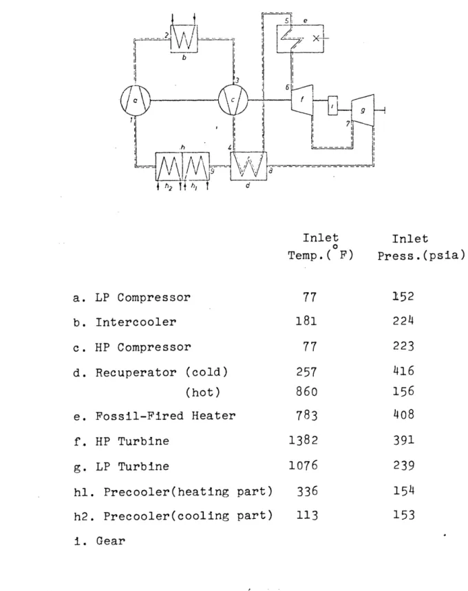
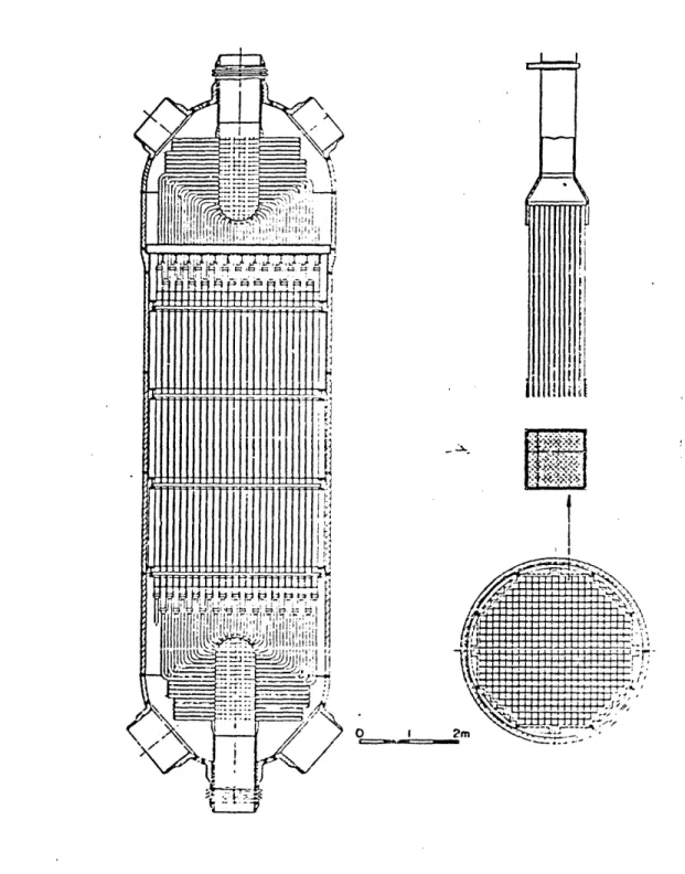
excellent modular design concepts have been published for regenerators -- Swiss and GA designs are shown in Figs. 3.2 and 3.3, and a GA precooler design is shown in Fig. 3.4. We have already called attention to the use of Incoloy tubing under service conditions which bracket those of the present application.
3.6 Turbomachinery
Although we rely heavily upon Oberhausen II turbomachinery design, and their operating experience will also be of exceptional interest, there are several factors which rule out use of a
'!carbon-copy' unit in the present application:
(a) Oberhausen, while rated at 50 MWe was designed to simulate a 300 MWe unit and is therefore larger and more expensive than need be for a system optimized around 50 MWe service only.
(b) We have selected a design operating pressure of 900 psia, about a factor of two higher than
Oberhausen.
(c) We have omitted the compressor intercoolers and operate our system at a higher overall heat-to-power ratio.
Nevertheless with Oberhausen experience in hand it should be a fairly straight forward task for turbomachinery manufacturers to design a unit for the present application. Several have
50
i
: E
}I
J4 l r iII :1I i I II14'
>-.n1 r T1 I T IT, g. f I It /W
-Il
Fig. 3.2 Swiss Federal Institute's Proposed Nuclear Gas Turbine Regenerator (L1)
i=a
-1=-1_
ri j :q. c 16 IE ol·U· ~'-g 1 :i 1 j 'i 1 !1 1:1 i i c: I ii ii slF3FF tli-i I i r!Ji
Ii I ( I j ii; i;liili[i1Iil
ii
1-,isyi' iII / //I1 I!jll1: ' '! I 31t i lillIji :1 '1IS -r·r FI : i il;e;et;cSFCiriiScF·=iS;F-i;i; I ' · r ' -I;i 0 1 2m51 .w o R Io~~ iI
--
7
-a
0I','
1-1
V
I
I--,~S
7'
0
.. . , -7 -, -7' 4-' (U 14 S z z bca) m, 0 F-I~a if _ . : m4~~~~~~~~~~~~
b E-4 I%-- ; = i i C) I C) g ~~~~~~~~~~~~~~~~~~~~~~~~~~~~~~~~~~~~. : e o3~~~~a Ha~~~~~~~~~~~~~~~~~~~~~~~~~~a
i
.i
I I g # z w b "-i vrX~~~~~~~~~~~~~~C
/I
8
F~~~~~~~~8 i fg~~~~~c 8I
5EC EI-ML ,lDCTr APOW 4" /TcAL C 2-MT5 -1. 5fQFAr AME 2. FPWTAL AJE LbP/> - .CQFig. 3.4 General Atomic HTGR/GT Precooler (G3)
52 (
\,
-ZJ;a=.
-1
; i S - I-I'1
I 7 'T 17 . 1 I I - I q tIOt
4 IR j Ialready participated in design studies with GA on the larger units required for central station electric utility service. Following the practice adopted for these larger designs we will also employ a single shaft arrangement, but in the present case we prefer a geared-shaft arrangement following
Oberhausen (and conventional gas turbine practice) as it allows a better match between requirements and machine characteristics because the compressor and high pressure turbine are not restricted to the same speed of rotation. Single shaft machines, moreover, have a better inherent protection against overspeed during loss-of-load transients than split shaft machines due to the natural damping effect of the compressor and the greater system inertia. A single shaft design also has fewer components - hence lower capital costs, and a lower starting motor power suffices.
On the other hand, the single-shaft arrangment is
somewhat less flexible from a control standpoint, and requires higher bypass flow rates than the split-shaft design.
Axial flow machines are specified because of their high efficiency, design flexibility and ease of manufacture.
One additional design objective is worthy of note. Con-sidering the component sizes, weights and the compact layout
possible, an attempt should be made to shop-fabricate the turbine plant loops as modules which can be transported to the site as a unit.
3.7 System Control and Load Tailoring
Control of the present HTGR/GT unit differs in two important respects from that of the larger units being designed for central
station electric utility system service:
(a) the subject unit is load following, not base-loaded, since we have assumed stand-alone service and (at least for the reference design) no storage provisions for electric or thermal power.
(b) the subject unit is a total energy plant, hence must simultaneously satisfy both an electric and a thermal
demand.
In spite of these differences, proven techniques are available for closed-cycle turbine plant control which appear adequate for the proposed application, namely:
(1) Part-load following:
rapid response -- compressor bypass control slow response -- helium inventory (pressure
level) control (2) Loss-of-load transient:
compressor bypass control to limit turbine overspeed to < 120%
(3) Emergency shutdown: shutdown bypass valve
(4) Normal startup and shutdown:
starting motor or alternator with starting system electric power provided from grid, standby FFGT, or emergency dieselsL.
Additional flexibility can be achieved by the ability to vary reactor outlet (hence turbine inlet) temperature and the precooler water (hence compressor inlet) temperature. However the full range of control required can be obtained by the
combined use of inventory and compressor bypass: the former permits nearly constant plant efficiency over a power range spanning more than 50% of design output and the latter permits a 40% increase in thermal energy available to the utility
system at 20% bypass flow and essentially constant reactor power. Figure 3.5 shows a schematic of the power conversion system control features -- the resemblance to Oberhausen II is evident.
Although inventory control is employed, it should be noted that this option will only be used for slow variations in turbine plant operating conditions - over a minimum interval of half-a-day or so: for example, in preparation for weekend load reductions, or on a much longer time scale for adjustment to match seasonal load patterns or long term changes in the demand-growth spectrum. Two reasons motivate this restriction: the desire to limit pressure cycling of the 1HX units, and to use only the normal helium makeup and storage system - thereby avoiding the expense and complexity of installing a rapid gas transfer system and additional storage tanks.
--
----
----_ -_
I
a) Cd a) 4 O V o o1 0 4) U) Ct O a) O P- E-i cd 03 0 a: 30
0
0
4- U) U H -4a a
c) o h 0.
00
a)
a) ,1 O HCM CY a) 4-, Cvl o Cd o bo Cd 4-, O .4 JL4 0 O 0 HCd U) cd Eq u > a) bO bC a 4 oo
EV
H- 0 HC rl) C E-1 .. e. e . Cd 0 S: r~Cd C 4o o O o oo a) o a O a X O dS
Cd H x k O ( DP-V:
0;
:..
..
ee ~p~ 56 4-, .rl 03 aD 0 a) 0 O 0 O CI 4-, O Cd a)4
C) 0 (3 00 Cd 0 U-\ 4-aD 4-E Cd E a)9- 4-03 n 0 Cda) Cl) !
©
I- --OWe will discuss the related subject of reactor system
control in a later chapter, but call attention to the fact that the large heat capacity of the graphite in the reactor core make the constant-temperature control mode a natural choice for
implementation.
Finally, the desirability of using absorptive air condi-tioning and/or heat pumps to tailor the load to match the
normal output of the power plant, and in particular to achieve a better seasonal balance, is noted. A more detailed discussion on this aspect is presented in Appendix B.
3.8 Summary
Table 3.4 presents a condensed summary of the major features of the system developed up to this point. Perhaps the most
interesting observation is that the use of an indirect cycle has involved a lower price than might at first be imagined: something on the order of four million dollars in direct com-ponent costs, but only 750F in turbine inlet temperature. The
efficiency is comparable to that of a CNSG-type PWR, but effi-ciency per se does not tell the whole story since the IITGR waste heat is directly useful, and since the ratio of thermal
to-electrical demand will usually exceed 2:1 in most prospective applications -- making higher efficiency unnecessary.
58
Table 3.4
Summary of Design Features
Power conversion: Layout: Capacity: Efficiency: Pressure Vessel: Turbomachinery: Regeneration: Compressor Intercooling: Max. System Temp.
Max. System Pressure:
Core Thermal Rating:
Indirect Brayton Cycle Non-integral, two loops
100 MWe, < 200 MWth
33%
Steel Pressure Vessel Single (geared) Shaft
50 MW Turboset per loop
87% None 15000F (Primary) 14250F (Secondary) 900 psi (Secondary) 400 psi (Primary) 278 MWth
Chapter 4
PRIMARY AND AUXILIARY SYSTEMS
4.1 Introduction
In this chapter w will consider key aspects of the design of the various reactor systems. The general approach has
been to rely heavily upon the concepts proven in practice in
the operational prototype HTGR plants: Peachbottom I (re-cently decomissioned) Dragon and AVR. In addition the sys-tem designs of Geesthacht II, a HTGR/GT unit carried through to a point just short of construction, and the JAERI HTGR,
presently on the drawing boards, proved to be useful. Various characteristics of interest from these units are summarized in Table 4.1.
In addition to the obvious savings achieved by not having to totally re-engineer the plant design this philosophy is particu-larly attractive because of the high reliability achieved in these prior designs. For example, Peachbottom's lifetime forced outage rate was less than 5%, and the AVR load factor was an
outstanding 88% during 1973.
A final point to note is that even though the present design, unlike Peachbottom, AVR or Dragon, is mated to a gas turbine plant, the HTGR is not particularly sensitive to power cycle design. Both GA and European designers note in reference to their direct cycle designs that the balance of
the plant other than the main coolant loops is largely unaffected. In the present instance the use of an indirect cycle gives even greater assurance of similitude.
O